PRINTER
US20160023855A1
2016-01-28
14/808,226
2015-07-24
Abstract:
A printer includes a body, a feed tray that stores paper and is slidable between a first position corresponding to a drawn-out position from the body and a second position corresponding to an accommodated position, a printer that performs printing on paper supplied from the feed tray located at the second position, and a regulation unit provided on the body and pivotable between a first posture not regulating movement of the feed tray and a second posture regulating movement of the feed tray. The feed tray includes a pressing portion and a regulated portion.
Interested in similar patents?
Get notified when new applications in this technology area are published.
Classification:
B65H1/266 » CPC main
Supports or magazines for piles from which articles are to be separated with auxiliary supports to facilitate introduction or renewal of the pile Support fully or partially removable from the handling machine, e.g. cassette, drawer
B65H1/26 IPC
Supports or magazines for piles from which articles are to be separated with auxiliary supports to facilitate introduction or renewal of the pile
B65H1/04 » CPC further
Supports or magazines for piles from which articles are to be separated adapted to support articles substantially horizontally, e.g. for separation from top of pile
Description
BACKGROUND OF THE INVENTION
1. Field of the Invention
The present invention relates to a printer which includes a feed tray slidable with respect to a body of the printer.
2. Description of the Related Art
An image forming apparatus (printer) which includes a mechanism for locking a paper storage cassette (feed tray) within a body of the image forming apparatus (body) in a slid and accommodated state of the cassette is known (for example, see JP 7-25489 A).
There is further known, for example, a printer which includes a mechanism for allowing a feed tray to re-store paper subjected to printing on one surface of the paper in a storage state that the surface of the paper on the side opposite to the surface set prior to printing faces upward at the time of duplex printing. According to this type of printer, the feed tray is required to be accurately located at a predetermined position of the body of the printer to allow accurate alignment between the printing position on the one surface of the paper and the printing position on the other surface of the paper at the time of re-storage of the paper within the feed tray. It is therefore required that a feed tray of a printer is accurately located at a predetermined position of a body of the printer.
However, such a problem arises from JP 7-25489 A that a feed tray is difficult to be accurately located at a predetermined position with respect to a body of a printer.
SUMMARY OF THE INVENTION
Preferred embodiments of the present invention provide a printer capable of accurately setting a feed tray at a predetermined position with respect to a body of the printer.
A printer according to an aspect of various preferred embodiments of the present invention includes a body; a feed tray that stores paper, and is capable of sliding between a first position corresponding to a drawn-out position from the body and a second position corresponding to an accommodated position within the body; a printing unit that performs printing on paper supplied from the feed tray located at the second position; and a regulation unit provided on the body, and pivotable between a first posture not regulating sliding of the feed tray and a second posture regulating sliding of the feed tray. The feed tray includes a pressing portion that presses a portion of the regulation unit in a first direction from the first position toward the second position to pivot the regulation unit from the first posture to the second posture when the feed tray slides from the first position and reaches the second position, and a regulated portion pressed in the first direction by another portion of the regulation unit moved to the second posture by the pressing portion at the time of arrival of the feed tray at the second position.
According to this structure, the pressing portion pivots the regulation unit from the first posture to the second posture when the feed tray comes into the accommodated state within the body and reaches the second position. Then, the regulation unit in the second posture presses the regulated portion of the feed tray in the first direction.
Accordingly, when the feed tray is located at the second position within the body, the regulation unit presses the feed tray in the first direction, thus regulating sliding of the feed tray in the first direction from the second position. This structure therefore allows accurate setting of the feed tray at the second position at least in the sliding direction of the feed tray.
For example, the regulation unit may pivot between the first posture and the second posture, and maintain each of the first posture and the second posture until a force having a strength equal to or larger than predetermined strength is applied to the regulation unit.
In this case, the regulation unit maintains the second posture in the state of the feed tray located at the second position until a force having a strength equal to or larger than the predetermined strength is applied. Accordingly, this structure maintains the feed tray at the second position even under application of a force in the direction opposite to the first direction when the strength of the applied force is smaller than the predetermined strength.
The regulation unit may include: a pivoting portion pivotable between the first posture and the second posture around a pivot axis extending parallel or substantially parallel to a second direction crossing the first direction; a first portion connecting with the pivoting portion, and extending in a direction crossing the pivot axis; a second portion connecting with the pivoting portion, and extending in a direction crossing the pivot axis and different from the extension direction of the first portion; and a maintaining portion that maintains the pivoting portion in each of the first posture and the second posture until a force having a strength equal to or larger than the predetermined strength is applied to the pivoting portion.
According to this structure, the regulation unit is pivotable from the first posture to the second posture by utilizing the force of the feed tray exerted during movement of the feed tray from the first position to the second position.
The maintaining portion may include a first spring that includes one of a first projection and a first recess, and urges the one of the first projection and the first recess toward the pivoting portion; and the other of the first projection and the first recess provided at two positions of an outer circumference of the pivoting portion, and fitted to the one of the first projection and the first recess at one and the other of the two positions of the pivoting portion in the first posture and the second posture of the pivoting portion, respectively. In this case, the maintaining portion maintains the pivoting portion in each of the first posture and the second posture by fitting between the one of the first projection and the first recess of the first spring and the other of the first projection and the first recess provided at one of the two positions of the pivoting portion until a force having a strength equal to or larger than the predetermined strength is applied to the pivoting portion.
The second portion may include a first protrusion protruding in the movement direction of the second portion at the time of pivoting from the first posture to the second posture. In this case, the regulation unit may retain the feed tray at the second position by bringing the first protrusion of the second portion into contact with the regulated portion when the feed tray reaches the second position.
According to this structure, the second portion includes the first protrusion. In this case, the first protrusion of the second portion is securely brought into contact with the regulated portion even when the pivoting amount of the regulation unit from the first posture to the second posture is reduced. This structure produces contact between the regulation unit and the regulated portion only by a small pivoting amount of the regulation unit. Accordingly, this structure decreases abrasion resulting from this contact, and sets the feed tray at the second position with high accuracy even after repetitive opening and closing of the feed tray with respect to the body a large number of times.
The feed tray may include an inclined surface inclined relative to the first direction, and a third direction crossing the first direction and the vertical direction. In this case, the body may include a first contact portion that comes into contact with the inclined surface in the third direction when the feed tray reaches the second position, and a second contact portion that is disposed at a position different from the position of the first contact portion in the first direction, and comes into contact with the feed tray in the third direction.
According to this structure, the first contact portion and the second contact portion are disposed at different positions in the first direction. The feed tray is brought into contact with the first contact portion and the second contact portion in the third direction. In this case, the feed tray is movable toward a side in the third direction by the function of the first contact portion and the second contact portion. More specifically, the feed tray is movable toward one side of the body in the third direction as a direction crossing the first direction in the horizontal direction. Accordingly, the feed tray is allowed to be accurately set at the second position, and a position on one side in the third direction.
The second contact portion may include a second projection, and a second spring that urges the second projection toward one side in the third direction. In this case, the feed tray may include a second recess fitted to the second projection of the second contact portion when the feed tray is located at the second position.
According to this structure, the second projection of the second contact portion is urged in the third direction by the second spring such that the second projection of the second contact portion is fitted to the second recess of the feed tray. Accordingly, the feed tray is securely movable toward the body on a side in the third direction.
The pressing portion may be a second protrusion that projects in the first direction from a portion of the feed tray on a side in the third direction. In this case, the second protrusion may include the inclined surface. A portion of the body on the side in the third direction further may include a through hole through which the second protrusion penetrates. The first contact portion may be a portion of an inner circumference of the through hole.
According to this structure, the inclined surface is provided on the second protrusion corresponding to the pressing portion. In this case, the second protrusion performs two functions of changing the posture of the regulation unit, and achieving movement toward a side in the third direction by the function of the first contact portion. Accordingly, simplification in the configuration of the feed tray is achievable.
The printer may further include a re-storage unit that re-stores the paper subjected to printing on one surface of the paper by the printing unit in the feed tray in a storage state that the surface of the paper on the side opposite to the surface set prior to printing by the printing unit faces upward.
According to this structure, the printer which includes the re-storage unit realizing duplex printing allows accurate setting of the feed tray at the second position. Accordingly, the printer performs highly accurate duplex printing.
According to various preferred embodiments of the present invention, a feed tray is accurately set at a predetermined position with respect to a body of a printer.
The above and other elements, features, steps, characteristics and advantages of the present invention will become more apparent from the following detailed description of the preferred embodiments with reference to the attached drawings.
BRIEF DESCRIPTION OF THE DRAWINGS
FIG. 1 is a perspective view illustrating an external appearance of a printer according to a preferred embodiment of the present invention.
FIG. 2 is a perspective view illustrating a body and a feed tray in an accommodated state without a housing and other elements of the printer shown in FIG. 1.
FIG. 3 is a perspective view illustrating the body and the feed tray in a drawn-out state of the feed tray.
FIG. 4 is a schematic view illustrating an internal configuration of the printer.
FIG. 5 is a view illustrating a first regulation unit and a second regulation unit when the feed tray is regulated by the first regulation unit.
FIG. 6 is a view illustrating the first regulation unit and the second regulation unit when the feed tray is not regulated by the first regulation unit.
FIG. 7 is a view illustrating a relationship between the feed tray and a regulation unit when the regulation unit is in a second posture.
FIG. 8 is a view illustrating a relationship between a pressing portion of the feed tray and a through hole of the body when the feed tray is located at a second position.
FIG. 9 is a view illustrating a relationship between the pressing portion of the feed tray and the through hole of the body when the feed tray is located at a first position.
FIGS. 10A and 10B are schematic views illustrating a relationship between the feed tray and the body as viewed in the direction of the Z axis when the feed tray is located at the second position.
FIG. 11 is a schematic view illustrating a relationship between the feed tray and the body as viewed in the direction of the Z axis when the feed tray is located at the first position.
DETAILED DESCRIPTION OF THE PREFERRED EMBODIMENTS
Preferred embodiments according to the present invention are hereinafter described in detail with reference to the drawings. The preferred embodiments described herein are preferred specific examples of the present invention. Numerical values, shapes, materials, constituent elements, positions and connection manners of the constituent elements, and others presented in the following preferred embodiments are given only by way of example, and not intended to limit the scope of the present invention. The scope of the present invention is only defined by the appended claims. Accordingly, constituent elements described and shown in the following preferred embodiments but not contained in the independent claims are regarded as elements not necessarily essential for the present invention, but adopted to constitute a more preferred exemplary embodiment of the present invention.
In each of the following figures, directions in the figure are described using an XYZ coordinate system with reference to the structural elements of a printer. In the XYZ coordinate system, a plane including a medium carrying surface of a feed tray, described in more detail below, is defined as an XY plane, a direction in which the feed tray is inserted or removed from a printer is defined as the Y axis, a direction perpendicular or substantially perpendicular to the Y axis in the XY plane is defined as the X axis, and a direction perpendicular or substantially perpendicular to the X axis and the Y axis is defined as the Z axis.
Configurations of a printer according to preferred embodiments of the present invention are hereinafter described.
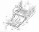
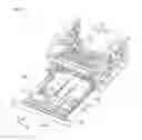
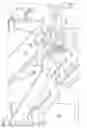
FIG. 1 is a perspective view illustrating an external appearance of a printer according to the present preferred embodiment. FIG. 2 is a perspective view illustrating a body and a feed tray in an accommodated state without a housing and other elements of the printer. FIG. 3 is a perspective view illustrating the body and the feed tray in a drawn-out state of the feed tray.
As illustrated in FIGS. 1 through 3, a printer 100 includes a body 10, a feed tray 20, a housing 30 covering the body 10 and the feed tray 20, and at least a first regulation unit 40.
The body 10 includes a first body portion 11, a second body portion 12, and a junction unit 13.
The first body portion 11 and the second body portion 12 are provided at a first end and a second end of the printer 100 in a direction of the X axis, respectively. The feed tray is sandwiched between the first body portion 11 and the second body portion 12 in the direction of the X axis to connect with the body 10 so as to be slidable in the direction of the Y axis. A guide rail 14 along which the feed tray 20 is slidable is provided on each wall surface of the first body portion 11 and the second body portion 12 on the inner side in the direction of the X axis and in the lower portions of the first body portion 11 and the second body portion 12.
The junction unit 13 joins the first body portion 11 and the second body portion 12 with a predetermined space between the first and second bodies 11 and 12 and allows connection of the feed tray 20 such that the feed tray 20 is slidable in the direction of the Y axis. The junction unit 13 is positioned above the feed tray 20 in the accommodated state of the feed tray 20 within the body 10.
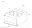
The feed tray 20 is a tray that stores paper. The feed tray 20 is slidable between a first position and a second position corresponding to positions of the feed tray 20 with respect to the body 10. The first position corresponds to a position of the feed tray 20 drawn out from the body 10. The second position corresponds to a position of the feed tray 20 accommodated within the body 10. In more detail, the feed tray 20 includes a front wall 21, a first side wall 22, a second side wall 23, and a bottom plate 24 as illustrated in FIG. 3.
The front wall 21 defines a portion of the exterior of the printer 100, and includes a grip 21a to be held by a user when the feed tray 20 is drawn out in the direction toward the negative side of the Y axis.
The first side wall 22 is a side wall provided on the feed tray 20 on the negative side of the X axis. A groove (not shown) in the first side wall 22 is connected with the guide rail 14 of the first body portion 11 to allow sliding of the first side wall 22.
The second side wall 23 is a side wall provided on the feed tray 20 on the positive side of the X axis. A groove 23a in the second side wall 23 is connected with the guide rail 14 of the second body portion 12 to allow sliding of the second side wall 23.
The bottom plate 24 provided in the lower portion of the feed tray 20 is a plate-shaped component extending in parallel or substantially in parallel with the horizontal plane, and includes a carrying surface on which paper is placed in a direction parallel or substantially in parallel with the horizontal plane. A guide (not shown) is provided on the bottom plate 24 to set paper of a predetermined size at a predetermined position of the carrying surface. Accordingly, paper having a predetermined size is allowed to be set at a predetermined position by the use of the guide.
The housing 30 is a component which constitutes a portion of the exterior of the printer 100 together with the front wall 21 of the feed tray 20. The housing 30 includes a discharge portion 31 through which paper after printing is discharged. Paper having reached the discharge portion 31 is stacked on the discharge portion 31.
The first regulation unit 40 regulates the feed tray to prevent movement of the feed tray 20 from the second position while the feed tray 20 is in the second position.
An internal configuration of the printer 100 is hereinafter described.
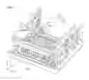
FIG. 4 is a schematic view illustrating the internal configuration of the printer.
As illustrated in FIG. 4, a printing unit 120 and a re-storage unit 130 are preferably provided within the housing 30.
The printing unit 120 performs printing on paper which has been delivered from the feed tray 20 located at the second position. The printing unit 120 includes a charging unit 102, an exposure unit 103, a developing device 104, a transfer roller 105, a cleaning device 106, and a fixing unit 108. The housing includes a conveyance path 109 along which paper 101 as a recording medium supplied to the feed tray 20 is conveyed toward the discharge portion 31. The paper 101 supplied to the feed tray 20 is conveyed along the conveyance path 109 by operation of a pair of resist rollers 111.
The charging unit 102 charges the surface of a photosensitive roller 110 (described later). The charging unit 102 preferably includes a corona discharge device, for example, which applies high voltage by using fine wires or the like as electrodes for discharge. Alternatively, the charging unit 102 may include a charging device which applies voltage in a state of contact between a charging member, such as a charging roller as a typical example, and the surface of the photosensitive roller 110, in place of the corona discharge device.
The exposure unit 103 forms an electrostatic latent image on the surface of the photosensitive roller 110 by applying laser beams to the surface of the photosensitive roller 110 based on image data transmitted from an external device such as a personal computer (not shown).
The developing device 104 develops the electrostatic latent image formed on the surface of the photosensitive roller 110 by causing adhesion between developer and the electrostatic latent image. A visible image is formed on the surface of the photosensitive roller 110 after development of the electrostatic latent image. The developer preferably is single-component developer constituted only by toner having magnetism, for example. Alternatively, the developer may be double-component developer constituted by toner and carriers.
The transfer roller 105 transfers the visible image formed on the surface of the photosensitive roller 110 to the paper 101 conveyed from the feed tray 20 along the conveyance path 109.
The cleaning device 106 removes developer remaining on the surface of the photosensitive roller 110 after transfer of the visible image to the paper 101.
The fixing unit 108 fixes the visible image to the paper 101 by heating and pressurizing the paper 101 having received the transferred visible image. The paper 101 having passed through the fixing unit 108 is discharged to the discharge portion 31 by operation of a pair of discharge rollers 112.
The re-storage unit 130 is a mechanism associated with duplex printing on the paper 101, and used when duplex printing on the paper 101 is selected and performed. More specifically, the re-storage unit 130 corresponds to a conveyance path 113 which re-stores the paper 101 subjected to printing on one surface of the paper 101 by the printing unit 120 within the feed tray 20 in a storage state such that the surface of the paper on the side opposite to the surface set prior to printing by the printing unit 120 faces upward. In more detail, the re-storage unit 130 is a conveyance path which conveys the printed paper toward the feed tray 20 by reverse pivoting of rollers after the paper 101 passes through the printing unit 120.
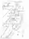
The feed tray 20 is regulated by the first regulation unit 40 provided on the body 10 and acting on a second regulation unit 50 (detailed later) of the feed tray 20 such that the feed tray 20 does not move back toward the first position after the feed tray 20 moves from the first position to the second position. The details of the first regulation unit 40, and the second regulation unit 50 provided on the feed tray 20 are hereinafter described.
FIG. 5 is a view illustrating the first regulation unit and the second regulation unit when the feed tray is regulated by the first regulation unit (i.e., when the feed tray is located at the second position). FIG. 6 is a view illustrating the first regulation unit and the second regulation unit when the feed tray is not regulated by the first regulation unit (i.e., when the feed tray is located at the first position). FIGS. 5 and 6 are enlarged views of an area A1 in FIG. 2.
The first regulation unit 40 is disposed on the first body portion 11 of the body 10, and is pivotable between a first posture not regulating sliding of the feed tray 20, and a second posture regulating sliding of the feed tray. More specifically, the first regulation unit 40 includes a first portion 41, a second portion 42, a pivoting portion 43, and a maintaining portion 44.
The first portion 41 is a bar-shaped member extending from the pivoting portion 43 in a direction crossing a pivot axis of the pivoting portion 43. The second portion 42 is a bar-shaped member extending from the pivoting portion 43 in a direction crossing the pivot axis of the pivoting portion 43 and different from the extension direction of the first portion 41. The pivoting portion 43 is a member pivotable between the first posture and the second posture around a pivot axis that is parallel or substantially parallel to a second direction (for example, the Z axis direction in this preferred embodiment) crossing a first direction (for example, the Y axis direction in this preferred embodiment). The first portion 41, the second portion 42, and the pivoting portion 43 of the first regulation unit 40 are preferably formed integrally with each other to define an L shape. The pivoting portion 43 of the first regulation unit 40 corresponds to a connection portion between the first portion 41 and the second portion 42. The second portion 42 includes a first protrusion 42a which projects in the movement direction of the second portion 42 at the time of pivoting from the first posture to the second posture.
The maintaining portion 44 maintains the pivoting portion 43 in each of the first posture and the second posture until a force having a strength equal to or larger than a predetermined strength is applied to the pivoting portion 43. More specifically, the first regulation unit 40 pivots between the first posture and the second posture, and maintains each of the first posture and the second posture until a force with a strength equal to or larger than the predetermined strength is applied.
FIG. 7 is a view illustrating a relationship between the feed tray and the regulation unit when the regulation unit is located at the second posture.
As illustrated in FIG. 7, the maintaining portion 44 of the first regulation unit 40 includes a first spring 45, and a first recess 43a and a first recess 43b in the pivoting portion 43. The first spring 45 includes a first projection 45a fitted to the first recess 43a and the first recess 43b, and urges the first projection 45a toward the pivoting portion 43. The first spring 45 applies an urging force toward the pivot axis of the pivoting portion 43. The two first recesses 43a and 43b are provided in the outer circumference of the pivoting portion 43, and fitted to the first projection 45a of the first spring 45 when the pivoting portion 43 is in the first posture and the second posture, respectively. When the first projection 45a of the first spring 45 is fitted to the first recess 43a of the pivoting portion 43, the first regulation unit 40 comes into the first posture. When the first projection 45a of the first spring 45 is fitted to the first recess 43b of the pivoting portion 43, the first regulation unit 40 comes into the second posture. The first spring 45 may be either a coil spring or a flat spring, for example.
As discussed above, the maintaining portion 44 maintains the pivoting portion 43 in each of the first posture and the second posture by fitting between the first projection 45a of the first spring 45 and one of the two recesses of the pivoting portion 43 in each of the first posture and the second posture until a force having a strength equal to or larger than the predetermined strength is applied to the pivoting portion 43. When a force smaller than the predetermined strength is applied to the pivoting portion 43 in the state that the first projection 45a of the first spring 45 is fitted to one of the first recesses 43a and 43b of the pivoting portion 43, the maintaining portion 44 maintains the state of fitting between the first projection 45a of the first spring 45 and the corresponding one of the first recesses 43a and 43b of the pivoting portion 43. On the other hand, when a pivoting force having a strength larger than the predetermined strength is applied to the pivoting portion 43, the maintaining portion 44 cancels the fitting between the first projection 45a of the first spring 45 and one of the first recesses 43a and 43b of the pivoting portion 43 based on application of the pivoting force having a strength equal to or larger than the predetermined strength and in excess of the urging force of the first spring 45. The maintaining portion 44 maintains the pivoting portion in the first posture when the first projection 45a of the first spring 45 is fitted to the first recess 43a of the pivoting portion 43. On the other hand, the maintaining portion 44 maintains the pivoting portion 43 in the second posture when the first projection 45a of the first spring 45 is fitted to the first recess 43b of the pivoting portion 43. When a force having a strength equal to or larger than the predetermined strength is applied to the first portion 41 in accordance with sliding of the feed tray 20 to the second position, the first regulation unit 40 cancels the first posture maintained by the maintaining portion 44, and allows the maintaining portion 44 to maintain the second posture after pivoting to the second posture.
The second regulation unit 50 is provided on a portion of the first side wall 22 of the feed tray 20 on the negative side of the X axis and on the positive side of the Y axis. The second regulation unit 50 includes a pressing portion 51, and a through hole 52 corresponding to a regulated portion. When the feed tray 20 slides and reaches the second position from the first position, the pressing portion 51 presses the first portion 41 corresponding to a portion of the first regulation unit 40 toward the positive side of the Y axis (i.e., in the direction from the first position toward the second position) to pivot the first regulation unit 40 from the first posture to the second posture. The pressing portion 51 is a second protrusion provided at a predetermined position of the first side wall 22 of the feed tray 20, and protruding from the predetermined position toward the positive side of the Y axis. A tip 51b of the pressing portion 51 comes into contact with the first portion 41.
The through hole 52 is located in the first side wall on the negative side of the Y axis with respect to the pressing portion 51. When the feed tray 20 reaches the second position, the first protrusion 42a of the second portion 42 of the first regulation unit 40 thus pivoted penetrates the through hole 52. As a result, a portion 52a located in the first side wall 22 and constituting the through hole 52 on the positive side of the Y axis is brought into contact with the first protrusion 42a of the second portion 42, and pressed toward the positive side of the Y axis. Accordingly, when the feed tray reaches the second position, the first regulation unit 40 regulates the feed tray 20 such that the feed tray 20 is retained at the second position by the contact between the first protrusion 42a of the second portion 42 and the through hole 52 as a regulated portion.
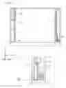
In addition, the feed tray 20 is movable toward the first body portion 11 side of the body 10 (i.e., negative side of the X axis) by a first contact portion (portion 61a constituting a through hole 61 on the positive side of the X axis) and a second contact portion 70. A configuration to move the feed tray 20 toward the negative side of the X axis is hereinafter described with reference to FIGS. 8 through 11.
FIG. 8 is a view illustrating a relationship between the pressing portion of the feed tray and the through hole of the body when the feed tray is located at the second position. FIG. 9 is a view illustrating a relationship between the pressing portion of the feed tray and the through hole of the body when the feed tray is located at the first position. FIGS. 8 and 9 are views illustrating an enlarged area A1 shown in FIG. 2. FIGS. 10A and 10B are schematic views illustrating a relationship between the feed tray and the body as viewed in the Z axis direction when the feed tray is located at the second position. More specifically, FIG. 10A is an entire view illustrating the relationship between the feed tray 20 and the body 10 when the feed tray 20 is located at the second position. FIG. 10B is an enlarged view illustrating a configuration of the second contact portion 70 which urges the feed tray 20 toward the negative side of the X axis. FIG. 11 is a schematic view illustrating a relationship between the feed tray and the body as viewed in the direction of the Z axis when the feed tray is located at the first position.
As illustrated in FIGS. 8 and 9, the pressing portion 51 of the feed tray 20 includes an inclined surface 51a inclined with respect to the directions of the X axis and the Y axis.
The first body portion 11 of the body 10 includes the through hole 61 through which the pressing portion 51 projecting in the direction of the Y axis penetrates. More specifically, the through hole 61 is located in a plate-shaped member projecting from the first body portion 11 toward the positive side of the X axis and extending parallel or substantially parallel to the X-Z plane. In addition, the first body portion 11 of the body 10 includes a through hole 63 through which the first portion 41 of the first regulation unit 40 penetrates, and a through hole 62 through which the second portion 42 penetrates. The through holes 62 and 63 in the body 10 are provided only when the first regulation unit 40 is provided outside the feed tray 20 with the side wall disposed between the first regulation unit 40 and the feed tray 20. The through holes 62 and 63 may be eliminated when the first regulation unit 40 is not disposed outside the side wall.
The portion 61a constituting the through hole 61 on the positive side of the X axis defines and functions as a first contact portion brought into contact with the inclined surface 51a of the pressing portion 51 from the positive side of the X axis when the feed tray 20 reaches the second position.
As illustrated in FIGS. 10A through 11, the second body portion 12 of the body 10 includes the second contact portion 70 disposed at a position different from the through hole 61 in the direction of the Y axis, and brought into contact with the feed tray 20 from the positive side of the X axis. The second contact portion 70 includes a bar-shaped member 71 extending in the direction of the Y axis, a pivoting shaft 72 pivoting the end of the bar-shaped member 71 on the positive side of the Y axis around the Z axis, and a second spring 73 urging the end of the bar-shaped member 71 on the negative side of the Y axis toward the negative side of the X axis. The end of the bar-shaped member 71 on the negative side of the Y axis includes a second projection 71a projecting toward the negative side of the X axis. Accordingly, the second projection 71a is urged toward the negative side of the X axis by the second spring 73. As illustrated in FIG. 10B, the second side wall 23 of the feed tray 20 on the positive side of the X axis includes a second recess 23b fitted to the second projection 71a of the bar-shaped member 71 of the second contact portion 70 when the feed tray 20 is located at the second position.
In this case, the through hole 61 constituting the first contact portion, and the second contact portion 70 are members that urge the feed tray 20 toward the negative side of the X axis, and disposed at different positions of the body 10 in the direction of the Y axis. This structure allows movement of the feed tray 20 toward the first body portion 11 of the body 10 throughout the width of the feed tray 20 in the direction of the Y axis. More specifically, the first contact portion (through hole 61) and the second contact portion 70 are capable of setting the position of the feed tray 20 at a predetermined position on a side in the X axis direction with respect to the body 10 (at such a position that the first side wall 22 of the feed tray 20 contacts the first body portion 11 throughout the width of the first side wall 22 in the direction of the Y axis).
According to the printer 100 in this preferred embodiment, the pressing portion 51 pivots the first regulation unit 40 provided on the body 10 from the first posture to the second posture when the feed tray 20 comes into the accommodated state within the body 10 and reaches the second position. Then, the first regulation unit 40 in the second posture presses the portion of the through hole 52 of the feed tray 20 toward the positive side of the Y axis.
Under the state that the feed tray 20 accommodated within the body 10 and located at the second position is pressed toward the positive side of the Y axis by the first regulation unit 40 provided on the body 10, sliding of the feed tray 20 in the first direction from the second position is regulated. Accordingly, the feed tray 20 is allowed to be accurately located at the second position at least in the sliding direction.
According to the printer 100 in this preferred embodiment, the first regulation unit 40 maintains the second posture in the state of the feed tray 20 located at the second position until a force having a strength equal to or larger than the predetermined strength is applied. This structure maintains the feed tray 20 at the second position even under application of a force to the feed tray 20 in the direction toward the negative side of the Y axis when the strength of the applied force is smaller than the predetermined strength.
According to the printer 100 in this preferred embodiment, the first regulation unit 40 is pivoted from the first posture to the second posture by utilizing the force of the feed tray 20 exerted during the movement of the feed tray 20 from the first position to the second position.
According to the printer 100 in this preferred embodiment, the second portion 42 of the first regulation unit 40 includes the first protrusion 42a. In this case, the first protrusion 42a of the second portion 42 is securely brought into contact with the portion constituting the through hole 52 even when the pivoting amount of the first regulation unit 40 from the first posture to the second posture is reduced. This structure produces contact between the first regulation unit 40 and the portion constituting the through hole 52 only by a small pivoting amount of the first regulation unit 40. Accordingly, this structure decreases abrasion resulting from this contact, and sets the feed tray 20 at the second position with high accuracy even after repetitive opening and closing of the feed tray 20 with respect to the body 10 a large number of times.
According to the printer 100 in this preferred embodiment, the second projection 71a on the bar-shaped member 71 of the second contact portion 70 is urged toward the negative side of the X axis by the second spring 73 such that the second projection 71a of the second contact portion 70 is fitted to the second recess 23b of the feed tray 20. Accordingly, the feed tray 20 is securely movable toward the body 10 on the negative side of the X axis.
According to the printer 100 in this preferred embodiment, the inclined surface 51a is located on a second protrusion corresponding to the pressing portion 51. In this case, the second protrusion performs two functions of changing the posture of the first regulation unit 40, and moving the first contact portion (through hole 61) toward the negative side of the X axis. Accordingly, simplification in the configuration of the feed tray 20 is achievable.
The printer 100 according to this preferred embodiment includes the re-storage unit 130 which re-stores the paper 101 subjected to printing on one of the surfaces by the printing unit 120 within the feed tray 20 in a storage state that the surface of the paper 101 on the side opposite to the surface set prior to printing by the printing unit 120 faces upward. In this case, the printer 100 which includes the re-storage unit 130 realizing duplex printing allows accurate setting of the feed tray 20 at the second position. Accordingly, the printer 100 performs highly accurate duplex printing for the paper 101.
While the printer according to a preferred embodiment of the present invention has been described, the present invention is not limited to this preferred embodiment.
According to the printer 100 in the foregoing preferred embodiment, the first regulation unit 40 provided on the body 10 preferably pivots around an axis parallel or substantially parallel to the direction of the Z axis to change between the two postures, i.e., the first posture and the second posture. However, the first regulation unit 40 may pivot around an axis parallel or substantially parallel to the direction of the X axis. In this case, the through hole corresponding to the regulated portion provided in the feed tray 20 is disposed in the bottom plate of the feed tray, for example. As can be understood, the pivot axis for the posture change of the first regulation unit between the first posture and the second posture may be an arbitrary axis crossing the Y axis corresponding to the sliding direction of the feed tray 20. When the pivot axis of the first regulation unit extends in a direction crossing the direction of the Y axis, a portion of the first regulation unit is caught by the through hole corresponding to the regulated portion of the feed tray. In addition, the regulated portion is only required to be pressed in the direction of the Y axis, wherefore the regulated portion may have other shapes such as a projecting shape instead of the shape of a through hole.
According to the printer 100 in the foregoing preferred embodiment, the first protrusion 42a preferably is provided on the second portion 42 of the first regulation unit 40. However, the first protrusion 42a may be eliminated. In this case, the second portion of the first regulation unit is brought into contact with the regulated portion when the angle of the first regulation unit at the time of the change from the first posture to the second posture is adjusted to substantially 90 degrees. In other words, the regulated portion of the feed tray 20 is allowed to be pressed toward the positive side of the Y axis even when the first protrusion 42a is not provided on the second portion 42.
According to the printer 100 in the foregoing preferred embodiment, the pivoting portion 43 of the maintaining portion 44 preferably includes the first recesses 43a and 43b, while the first spring 45 includes the first projection 45a to which the first recesses 43a and 43b are fitted. However, as an alternative configuration, the pivoting portion 43 may include two projections, while the first spring may include a recess to which the two projections are fitted.
According to the printer 100 in the foregoing preferred embodiment, the pressing portion 51 preferably includes the inclined surface brought into contact with the first contact portion to move the feed tray 20 toward the body 10 on the negative side of the X axis. However, the pressing portion 51 is not required to include the inclined surface. For example, based on the consideration that the feed tray 20 is only required to be moved toward the negative side of the X axis, an inclined surface may be provided at the end of the feed tray on the positive side of the X axis (i.e., the second side wall 23 of the feed tray 20). In this case, the first contact portion in contact with this inclined surface is provided on the second body portion 12. Even when the inclined surface and the first contact portion are positioned away from the pressing portion, movement of the feed tray 20 toward the negative side of the X axis is achievable. In this case, it is preferable that the inclined surface on the second side wall 23 is similarly disposed at a position not facing to the second contact portion 70 when the feed tray is located at the second position. This structure allows movement of the feed tray 20 toward the body 10 on the negative side of the X axis throughout the width of the feed tray 20 in the direction of the Y axis.
According to the printer 100 in the foregoing preferred embodiment, the re-storage unit 130 preferably is provided to perform duplex printing. However, the re-storage unit 130 is not necessarily required. Even in case of a configuration not performing duplex printing, the accuracy of an absolute position of printing with respect to the paper 101 improves with increases in the accuracy in positioning the feed tray 20.
Other preferred embodiments, examples, configurations, applications, etc. may be practiced by combining the foregoing preferred embodiments and modified examples.
Preferred embodiments of the present invention provide a printer capable of accurately setting a feed tray at a predetermined position with respect to a body of the printer, for example.
While preferred embodiments of the present invention have been described above, it is to be understood that variations and modifications will be apparent to those skilled in the art without departing from the scope and spirit of the present invention. The scope of the present invention, therefore, is to be determined solely by the following claims.
Claims
What is claimed is:1. A printer comprising:
a device body;
a printing unit;
a regulation unit provided on the device body;
a feed tray; and
a pressing portion and a regulated portion provided on the feed tray; wherein
the regulation unit is movable between a first posture and a second posture by contacting the pressing portion depending on a position of the feed tray; and
the regulation unit and the regulated portion engage with each other in the second posture.
2. The printer according to claim 1, wherein the feed tray stores a recording medium and is capable of sliding between a first position corresponding to a drawn-out position from the device body and a second position corresponding to an accommodated position within the device body.
3. The printer according to claim 2, wherein the regulation unit is pivotable between the first posture not regulating sliding of the feed tray and the second posture regulating sliding of the feed tray.
4. The printer according to claim 3, wherein the pressing portion presses a portion of the regulation unit in a first direction from the first position toward the second position to pivot the regulation unit from the first posture to the second posture when the feed tray slides from the first position and reaches the second position.
5. The printer according to claim 4, wherein the regulated portion is pressed in the first direction by another portion of the regulation unit moved to the second posture by the pressing portion at a time of arrival of the feed tray at the second position.
6. The printer according to claim 1, wherein the regulation unit pivots between the first posture and the second posture, and maintains each of the first posture and the second posture until a force having a strength equal to or larger than a predetermined strength is applied to the regulation unit.
7. The printer according to claim 6, wherein
the regulation unit includes:
a pivoting portion pivotable between the first posture and the second posture around a pivot axis extending parallel or substantially parallel to a second direction crossing the first direction;
a first portion connected with the pivoting portion, and extending in a direction crossing the pivot axis;
a second portion connected with the pivoting portion, and extending in a direction crossing the pivot axis and different from an extension direction of the first portion; and
a maintaining portion that maintains the pivoting portion in each of the first posture and the second posture until a force having a strength equal to or larger than the predetermined strength is applied to the pivoting portion.
8. The printer according to claim 7, wherein
the maintaining portion includes:
a first spring that includes one of a first projection and a first recess, and urges the one of the first projection and the first recess toward the pivoting portion; and
the other of the first projection and the first recess provided at two positions on an outer circumference of the pivoting portion, and fitted to the one of the first projection and the first recess of the first spring at one and the other of the two positions of the pivoting portion in the first posture and the second posture of the pivoting portion, respectively; and
the maintaining portion maintains the pivoting portion in each of the first posture and the second posture by fitting between the one of the first projection and the first recess of the first spring and the other of the first projection and the first recess provided at one of the two positions of the pivoting portion until a force having a strength equal to or larger than the predetermined strength is applied to the pivoting portion.
9. The printer according to claim 7, wherein
the second portion includes a first protrusion protruding in a moving direction of the second portion at a time of pivoting from the first posture to the second posture; and
the regulation unit retains the feed tray at the second position by bringing the first protrusion of the second portion into contact with the regulated portion when the feed tray reaches the second position.
10. The printer according to claim 1, wherein
the feed tray includes an inclined surface inclined relative to the first direction and a third direction crossing the first direction and the vertical direction; and
the body includes:
a first contact portion that comes into contact with the inclined surface in the third direction when the feed tray reaches the second position; and
a second contact portion that is disposed at a position different from the position of the first contact portion in the first direction, and comes into contact with the feed tray in the third direction.
11. The printer according to claim 10, wherein
the second contact portion includes a second projection, and a second spring that urges the second projection toward one side in the third direction; and
the feed tray includes a second recess fitted to the second projection of the second contact portion when the feed tray is located at the second position.
12. The printer according to claim 10, wherein
the pressing portion is a second protrusion that projects in the first direction from a portion of the feed tray on a side in the third direction;
the second protrusion includes the inclined surface;
a portion of the body on the side in the third direction further includes a through hole through which the second protrusion penetrates; and
the first contact portion is a portion of an inner circumference of the through hole.
13. The printer according to claim 1, further comprising a re-storage unit that re-stores the paper subjected to printing on one surface of the paper by the printing unit in the feed tray in a storage state such that the surface of the paper on the side opposite to the surface set prior to printing by the printing unit faces upward.
14. The printer according to claim 1, wherein the regulated portion includes a through hole in the feed tray.
15. The printer according to claim 14, wherein the through hole and the pressing portion define a second regulation unit.
16. The printer according to claim 1, wherein the pressing portion includes a protrusion protruding from the feed tray.
17. The printer according to claim 16, further comprising an inclined surface located on the protrusion.
18. The printer according to claim 1, wherein the regulation unit pivots about an axis that crosses a direction along which the feed tray slides.
19. The printer according to claim 7, wherein the maintaining portion includes a pivoting portion including recesses and a spring including a projection that fits in the recesses.
20. The printer according to claim 7, wherein the maintaining portion includes a pivoting portion including projections and a spring including a recess in which the projections fit.
Images & Drawings included:
Sources:
- United States Patent and Trademark Office - verify current appl. status at the USPTO↗
Similar patent applications:
- » 20180009696
3D PRINTER PRINTHEAD, 3D PRINTER USING SAME, METHOD FOR MANUFACTURING MOLDED PRODUCT BY USING 3D PRINTER, METHOD FOR MANUFACTURING ARTIFICIAL TOOTH BY USING 3D PRINTER, AND METHOD FOR MANUFACTURING MACHINABLE GLASS CERAMIC MOLDED PRODUCT BY USING 3D PRINTER - » 20170039009
Printers, printer controllers, printer software, or printer firmware for supporting wireless printing or printing over air - » 20070172293
Tape printer, tape printing system, ink ribbon cassette for a tape printer, method of loading a tape cassette and an ink ribbon cassette into a tape printer, and tape cassette for a tape printer - » 20240012588
Inkjet printer for displaying on display unit promotion message, non-transitory computer-readable recording medium storing computer-readable instructions for inkjet printer for displaying on display unit promotion message, printer for displaying on display unit promotion message and non-transitory computer-readable recording medium storing computer-readable instructions for printer for displaying on display unit promotion message - » 20200171744
3D printhead for use in a 3D printer, 3D printer with such a 3D printhead, method for operating such a 3D printer, and product produced by a 3D printer - » 20050253886
Ink jet printer, printer control unit, printer system including the same, and storage medium with the operation program of the printer control unit stored for controlling double-side printing - » 20240370212
INKJET PRINTER, NON-TRANSITORY COMPUTER-READABLE RECORDING MEDIUM STORING COMPUTER-READABLE INSTRUCTIONS FOR INKJET PRINTER, PRINTER AND NON-TRANSITORY COMPUTER-READABLE RECORDING MEDIUM STORING COMPUTER-READABLE INSTRUCTIONS FOR PRINTER - » 20050243361
Printer, printing system, print control method, storage medium used to store print control program for controlling a printer, and transmission device for transmitting print control program for controlling a printer - » 20050264602
Ink jet printer, method for controlling ink jet printer, and computer program product for ink jet printer - » 20050195226
Printer-control apparatus, printer-control method and printer
Recent applications in this class:
- » 20250122037 2025-04-17
SHEET FEEDING DEVICE AND IMAGE FORMING APPARATUS - » 20250100822 2025-03-27
SHEET CONVEYANCE APPARATUS AND IMAGE FORMING APPARATUS - » 20250042680 2025-02-06
SHEET FEEDING DEVICE AND IMAGE FORMING APPARATUS INCLUDING THE SAME - » 20240375894 2024-11-14
STORAGE, SHEET STACKING APPARATUS, AND IMAGE FORMING APPARATUS - » 20240375893 2024-11-14
SHEET STACKING APPARATUS AND IMAGE FORMING APPARATUS - » 20240359930 2024-10-31
PAPER FEED DEVICE AND IMAGE FORMING APPARATUS - » 20240228204 2024-07-11
MODULAR FEEDER - » 20240132310 2024-04-25
MODULAR FEEDER - » 20240116725 2024-04-11
Tray Insertion Velocity Limiting Mechanism - » 20240092594 2024-03-21
SHEET FEEDING DEVICE AND IMAGE FORMING APPARATUS