Method of making an assembly having a cast iron subassembly
US20160031005A1
2016-02-04
14/446,709
2014-07-30
✅ Patent granted
US 10,569,328 B2
2020-02-25
-
-
Devang R Patel
Brooks Kushman P.C.
2035-04-07
Abstract:
A method of making an assembly having a cast iron subassembly. The method may include providing a steel insert having a first joining surface and bonding the steel insert to a cast iron part to form a cast iron subassembly such that the first joining surface may be an exterior surface of the cast iron subassembly.
Assignee:
- ARVINMERITOR TECHNOLOGY, LLC 545 🇺🇸 Troy, MI, United States
Applicant:
Interested in similar patents?
Get notified when new applications in this technology area are published.
Classification:
B23K31/02 » CPC further
Processes relevant to this subclass, specially adapted for particular articles or purposes, but not covered by only one of the preceding main groups relating to soldering or welding
B23K20/227 » CPC further
Non-electric welding by applying impact or other pressure, with or without the application of heat, e.g. cladding or plating taking account of the properties of the materials to be welded with ferrous layer
B22D19/16 » CPC main
Casting in, on, or around objects which form part of the product for making compound objects cast of two or more different metals, e.g. for making rolls for rolling mills
B22D19/00 » CPC further
Casting in, on, or around objects which form part of the product
B23K35/306 » CPC further
Rods, electrodes, materials, or media, for use in soldering, welding, or cutting characterised by the composition or nature of the material; Selection of soldering or welding materials proper with the principal constituent melting at less than 1550 degrees C; Fe as the principal constituent with C as next major constituent, e.g. cast iron
B23K35/0255 » CPC further
Rods, electrodes, materials, or media, for use in soldering, welding, or cutting characterised by mechanical features, e.g. shape for use in welding
B23K2103/04 » CPC further
Materials to be soldered, welded or cut; Iron or ferrous alloys Steel or steel alloys
F16D2200/0013 » CPC further
Materials; Production methods therefor metallic; Ferro Cast iron
B23K9/232 » CPC further
Arc welding or cutting taking account of the properties of the materials to be welded of different metals
F16D65/10 » CPC further
Parts or details; Braking members; Mounting thereof Drums for externally- or internally-engaging brakes
B23K20/08 » CPC further
Non-electric welding by applying impact or other pressure, with or without the application of heat, e.g. cladding or plating by means of high energy impulses, e.g. magnetic energy Explosive welding
B23K35/0261 » CPC further
Rods, electrodes, materials, or media, for use in soldering, welding, or cutting characterised by mechanical features, e.g. shape for use in welding Rods, electrodes, wires
B23K35/30 » CPC further
Rods, electrodes, materials, or media, for use in soldering, welding, or cutting characterised by the composition or nature of the material; Selection of soldering or welding materials proper with the principal constituent melting at less than 1550 degrees C
B23K35/3053 » CPC further
Rods, electrodes, materials, or media, for use in soldering, welding, or cutting characterised by the composition or nature of the material; Selection of soldering or welding materials proper with the principal constituent melting at less than 1550 degrees C Fe as the principal constituent
B23K2103/06 » CPC further
Materials to be soldered, welded or cut; Iron or ferrous alloys Cast-iron alloys
B23K2103/18 » CPC further
Materials to be soldered, welded or cut Dissimilar materials
B60B35/00 » CPC further
Axle units; Parts thereof ; Arrangements for lubrication of axles
F16D2250/0007 » CPC further
Manufacturing; Assembly Casting
F16D2250/0015 » CPC further
Manufacturing; Assembly; Casting around inserts
B23K9/00 IPC
Electric welding or cutting
B23K9/00 IPC
Arc welding or cutting
B23K9/23 IPC
Arc welding or cutting taking account of the properties of the materials to be welded
B23K35/02 IPC
Rods, electrodes, materials, or media, for use in soldering, welding, or cutting characterised by mechanical features, e.g. shape
Description
TECHNICAL FIELD
This patent application relates to a method of making an assembly having a cast iron subassembly.
BACKGROUND
A method for arc welding of ductile cast iron is disclosed in U.S. Pat. No. 7,518,082.
SUMMARY
In at least one embodiment, a method of making an assembly having a cast iron subassembly is provided. The method may include providing a steel insert having a first joining surface and bonding the steel insert to a cast iron part to form a cast iron subassembly such that the first joining surface is an exterior surface of the cast iron subassembly. The method may further include providing a steel component having a second joining surface and abutting the second joining surface with the first joining surface. The method may further include joining the cast iron subassembly to the steel component proximate the first and second joining surfaces.
In at least one embodiment, a method of making an assembly having a cast iron subassembly. The method may include providing a first steel insert having a first faying surface and casting a first cast iron part about the first steel insert to make a first cast iron subassembly. The method may further include providing a second steel insert having a second faying surface and casting a second cast iron part about the second steel insert to make a second cast iron subassembly. The method may further include aligning the first faying surface with the second faying surface and welding the first cast iron subassembly along the first faying surface and the second faying surface such that the weld does not extend to and does not carburize the first cast iron part and the second cast iron part.
BRIEF DESCRIPTION OF THE DRAWINGS
FIG. 1 is a perspective view of a steel insert.
FIG. 2 is a perspective view of another steel insert.
FIGS. 3a and 3b are flowcharts of methods of making an assembly having a cast iron subassembly.
FIGS. 4a and 4b are section views of cast iron subassemblies joined to a steel component.
FIG. 5 a magnified cross-sectional view of an assembly.
FIGS. 6a and 6b are section views of cast iron subassemblies.
DETAILED DESCRIPTION
As required, detailed embodiments of the present invention are disclosed herein; however, it is to be understood that the disclosed embodiments are merely exemplary of the invention that may be embodied in various and alternative forms. The figures are not necessarily to scale; some features may be exaggerated or minimized to show details of particular components. Therefore, specific structural and functional details disclosed herein are not to be interpreted as limiting, but merely as a representative basis for teaching one skilled in the art to variously employ the present invention.
Axle components are generally made of a high strength cast iron due to the high stress and loading experienced by the axle components. The use of a high strength cast iron may enable the creation of the complex shapes of axle components and may minimize machining processes. Such axle components may include axle housings, brake drum assemblies, carrier assemblies, brake calipers, etc. The carbon and silicon content of the cast iron may impact the ability to weld accessories or other components to the axle components to form an axle assembly. The material compositions of flowable cast irons such as Gray Cast Iron, Ductile Cast Iron, and Compacted Graphite Iron are shown in Table 1 below.
| TABLE 1 |
| Material Composition of Various Cast Irons |
| Carbon | Silicon | Manganese | Sulfur | Phosphorous | |
| Iron Family | (wt %) | (wt %) | (wt %) | (wt %) | (wt %) |
| Gray Cast | 2.5-4.2 | 1.0-3.0 | 0.15-1.0 | 0.02-0.25 | 0.02-1.0 |
| Iron | |||||
| Ductile Cast | 3.0-4.0 | 1.8-3.0 | 0.10-1.0 | 0.01-0.03 | 0.01-0.1 |
| Iron | |||||
| Compacted | 2.5-4.0 | 1.5-3.0 | 0.10-1.0 | 0.01-0.03 | 0.01-0.1 |
| Graphite | |||||
| Iron | |||||
Gray cast iron is a type of cast iron that may contain a graphitic microstructure. The graphite may be in a flake form and stabilized by the silicon, which may inhibit the development of iron carbides. The graphite in flake form in gray cast iron may result in greater dissolving or diffusing of the graphite throughout the gray cast iron. The dissolving or diffusing of the graphite flakes may result in brittle areas in a part made of gray cast iron.
Ductile cast iron is a type of cast iron that contains a graphitic microstructure. The graphite may be in spheroidal or nodular form. The addition of manganese or magnesium may enable the graphite to take the nodular or spheroidal form. The spheroidal or nodular microstructure may provide a greater strength and enhance ductility as compared to gray cast iron.
A common form of ductile cast iron employed by manufacturers of axle assemblies is SAE J434. SAE J434 may come in various grades acceptable for use with axle assemblies. Some examples of the mechanical properties of SAE J434 grades are shown in Table 2 below.
| TABLE 2 |
| Mechanical Properties of Select SAE J434 Grades |
| SAE | Hardness | Tensile | Yield | |
| J434 | Range | Strength | Strength | % |
| Grade | (HBW) | (ksi) | (ksi) | Elongation |
| D400 | 143-170 | 58 | 40 | 18 |
| D450 | 156-217 | 65 | 45 | 12 |
| D500 | 187-229 | 73 | 50 | 6 |
Compacted graphite iron (CGI) is a type of cast iron that contains a graphitic microstructure. The graphite may be in a blunt flake or semi-nodular form. The semi-nodular microstructure may provide strength and ductility intermediate to gray cast iron and ductile cast iron.
The welding of parts made from cast iron may present various problems. The heat produced from welding parts made of cast iron may further dissolve or diffuse the graphite microstructure. The dissolving or diffusing may result in the formation of carbides, martensite, cementite, or bainite proximate the weld. The formations that include cementite may be referred to as “white cast iron”. These formations may reduce the strength of the parts made of cast iron. Therefore, industry standards generally warn against the welding of cast irons due to the potential loss of its original strength.
Commonly, cast steel may used to form the axle component and a cast steel accessory component may be welded to the cast steel axle component to form an axle assembly. The cast steel axle component and accessory component may be easily welded together. These accessory components may be brackets, housing snorkels, and other mounting components. Unfortunately, cast steel may have a greater cost than cast irons which may be cost prohibitive in some applications. Traditional manufacturing processes discourage welding of the cast iron axle components so as to not degrade part performance.
A possible solution to obviate the difficulties presented in welding cast iron parts is to provide a steel insert proximate the weld joint areas of the cast iron part. This may enable the welding of high stress components used as part of a vehicle axle assembly. The steel insert may enable non-brittle arc welding to bond a cast iron part to a steel component or other cast iron part, via the steel insert, using a traditional arc welding process.
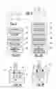
Referring to FIG. 1, the steel insert 10 may be a generally linear strip having tetragonal cross-section. The steel insert 10 may have a width 12, a thickness 14, and a length 16. The thickness 14 may be sized such that a weld does not penetrate past the thickness of the steel insert 10, to not affect the base cast iron parts. A surface of the steel insert 10 may define a first faying or joining surface 18. Referring to FIG. 2, the steel insert 10 may have a generally arcuate profile such that the steel insert 10 is configured as a continuous ring.
The steel insert 10 may be made of a low carbon steel such as SAE 1006, 1008, and 1010. Some examples of possible material compositions of the steel insert 10 are shown in Table 3 below.
| TABLE 3 |
| Material Compositions of Various SAE Grades |
| SAE | Carbon | Manganese | Phosphorus | Sulfur |
| Grade | (wt %) | (wt %) | (wt %) | (wt %) |
| 1006 | 0.08 | 0.35 max | 0.04 | 0.05 |
| 1008 | 0.1 | 0.30-0.50 | 0.04 | 0.05 |
| 1010 | 0.08-0.13 | 0.30-0.60 | 0.04 | 0.05 |
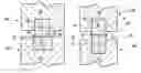
Referring to FIGS. 3a, 4a, and 4b, an exemplary method of manufacturing an assembly having a cast iron subassembly is shown. The steel insert 10, having a first joining surface 18, may be provided, at block 100. The first joining surface 18 may be spaced apart from an opposing mating surface.
At block 102, the steel insert 10 may be bonded to a cast iron part 40. The steel insert 10 may be placed into a mold (not shown) configured to receive the steel insert 10. The mold may permit a flowable cast iron be poured about the steel insert 10 such that the first joining surface 18 may be an exterior surface of the resulting cast iron subassembly. The steel insert 10 may alternatively be bonded to a cast iron part 40 using explosive welding or other known methods to form the cast iron subassembly.
As shown in FIG. 4a, the first joining surface 18 of the steel insert 10 may be flush with a surface 44 of the cast iron part 40 to form a cast iron subassembly 42a. As shown in FIG. 4b, the first joining surface 18 of the steel insert 10 may protrude from the surface 44 of the cast iron part 40 to form a cast iron subassembly 42b.
At block 104, a steel component 46 may be provided. The steel component 46 may be a cast steel bracket, snorkel, or other mounting component having a second joining surface 48.
At block 106, the steel component 46 may be positioned relative to the cast iron subassembly proximately abutting the first and second joining surfaces 18, 48, as shown in FIGS. 4a and 4b.
At block 108, the cast iron subassembly 42a or 42b may be joined to the steel component 46. The cast iron subassembly 42a or 42b may be joined to the steel component 46 proximate the first and second joining surfaces 18, 48 by a non-brittle arc weld 50. The welding process may be performed such that the weld does not penetrate beyond the steel insert thickness 14. This may inhibit the formation of white iron or other carbides within the cast iron subassembly 42a, 42b.
Referring to FIGS. 3b, 6a, and 6b, an exemplary method of making an assembly having multiple cast iron subassemblies is shown.
At block 200, a first steel insert 60 may be provided. The first steel insert 60 may be substantially linear and have a first faying surface 62. The first steel insert 60 may be placed into a mold configured to receive the first steel insert 60.
At block 202, the first steel insert 60 may be cast into a first cast iron part 64 to form a first cast iron subassembly 66a or 66b. A flowable cast iron may be cast about the first steel insert 60 such that the first faying surface 62 is an exterior surface of the first cast iron subassembly 66a or 66b.
The first steel insert 60 may have a first lateral surface 68. The first lateral surface 68 may extend from the first faying surface 62 and into the first cast iron part 64. The first lateral surface 68 may have a length greater than a length of the first faying surface 62 such that the first faying surface protrudes from a surface 78 of the first cast iron subassembly 66a or 66b.
At block 204, a second steel insert 70 may be provided. The second steel insert 70 may be substantially linear and have a second faying surface 72. The second steel insert 70 may be placed into a mold configured to receive the second steel insert 70.
At block 206, the second steel insert 70 may be cast into a second cast iron part 74. A flowable cast iron may be cast about the second steel insert 70 such that the second faying surface 72 may be an exterior surface that may be proximately flush with a surface 80 of the second cast iron part 74 to form a second cast iron subassembly 76a.
As shown in FIG. 6a, the second faying surface 72 of the second steel insert 70 may be proximately flush with a surface 80 of the second cast iron part 74 to form a cast iron subassembly 76a. As shown in FIG. 6b, the second faying surface 72 of the second steel insert 70 may protrude from the surface 80 of the second cast iron part 74 to form a cast iron subassembly 76b.
At block 208, the first cast iron subassembly 66a, 66b may be positioned relative to the second cast iron subassembly 76a, 76b. The cast iron subassemblies may be aligned such that first faying surface 62 is aligned with the second faying surface 72. The first and second faying surfaces 62, 72 may be abutted.
At block 210, the cast iron subassemblies may be welded together along the first faying surface 62 and the second faying surfaces 72 by weld 50.
Referring to FIG. 5, a cross-sectional view of a weld joint is shown. An interface 58 may be created between the steel insert 10 and the cast iron part 40 due to the casting process. The cast iron subassembly 42 may then be joined to the steel component 46 by a non-brittle arc weld 50.
The weld 50 may generate a weld pool 52. The area immediately adjacent to the weld 50 and the weld pool 52 may define a fusion zone 54 and a heat affected zone 56.
The fusion zone 54 may physically fuse or join the joining surfaces or faying surfaces together. The fusion zone 54 may at least partially melt the interface between the steel insert 10 and steel component 46 or the interface between the first and second steel inserts 60, 70.
During the welding process the cast steel insert 10 and/or the cast steel component 46 may be heated to near their fusion or melting temperature within the heat affected zone 56. The microstructure and the properties of the materials within the heat affected zone 56 may be altered due to the heat generated during the welding process.
The thickness 14 of the steel insert 10 may prevent the heat affected zone 56 from extending into the cast iron part 40 of the cast iron subassembly 42a, 42b so as to affect the material properties of the cast iron part 40. For example, if the cast iron part 40 is formed from ductile cast iron, the heat affected zone 56 may extend into the cast iron part 40. Within the cast iron part 40, an area proximate the fusion zone 54 or within the heat affected zone 56 may not resolidify as ductile cast iron because the graphite may precipitate as quasi-nodular. This non-resolidification may drastically reduce the ductility or strength of the cast iron part 40 formed from ductile cast iron. The cast steel insert 10 may limit the extension of the heat affected zone 56 to inhibit changes in the microstructure properties of the cast iron part 40 so as to not affect the durability or strength of the cast iron subassembly 42a, 42b.
The weld 50 may be performed such that the weld 50 does not extend to or engage the first cast iron part 64 or the second cast iron part 74 of their respective cast iron subassemblies. In addition, the heat affected zone 56 may not extend to the first cast iron part 64 or second cast iron part 74, which may inhibit carburizing or the conversion of the cast iron parts to white cast iron.
While exemplary embodiments are described above, it is not intended that these embodiments describe all possible forms of the invention. Rather, the words used in the specification are words of description rather than limitation, and it is understood that various changes may be made without departing from the spirit and scope of the invention. Additionally, the features of various implementing embodiments may be combined to form further embodiments of the invention.
Claims
What is claimed is:1. A method of making an assembly having a cast iron subassembly, comprising:
providing a steel insert having a first joining surface;
bonding the steel insert to a cast iron part to form a cast iron subassembly such that the first joining surface is an exterior surface of the cast iron subassembly;
providing a steel component having a second joining surface;
abutting the second joining surface with the first joining surface; and
joining the cast iron subassembly to the steel component proximate the first and second joining surfaces.
2. The method of claim 1 wherein cast iron subassembly is joined to the steel component by welding.
3. The method of claim 1 wherein the cast iron part is cast around the steel insert.
4. The method of claim 1 wherein the steel insert is configured as a ring.
5. The method of claim 1 wherein the cast iron part is made of ductile cast iron.
6. The method of claim 1 wherein the steel component is a cast steel bracket.
7. The method of claim 1 wherein the steel insert protrudes from the cast iron part.
8. A method of making an assembly having a cast iron subassembly, comprising:
providing a first steel insert having a first faying surface;
casting a first cast iron part about the first steel insert to make a first cast iron subassembly;
providing a second steel insert having a second faying surface;
casting a second cast iron part about the second steel insert to make a second cast iron subassembly;
aligning the first faying surface with the second faying surface; and
welding the first cast iron subassembly to the second cast iron subassembly along the first faying surface and the second faying surfaces such that the weld does not extend to and does not carburize the first cast iron part and the second cast iron part.
9. The method of claim 8 wherein the first cast iron subassembly and the second cast iron subassembly are axle housings.
10. The method of claim 8 wherein the first cast iron subassembly is welded to the second cast iron subassembly such that the first cast iron part and the second cast iron part are not converted to white cast iron.
11. The method of claim 8 wherein the first cast iron part is made of ductile cast iron.
12. The method of claim 8 wherein the first cast iron part is made of gray cast iron.
13. The method of claim 8 wherein the first steel insert is substantially linear.
14. The method of claim 8 wherein the first steel insert has a first lateral surface that extends from the first faying surface into the first cast iron part, wherein the first lateral surface has a length greater than the first faying surface.
15. The method of claim 8 wherein the assembly is a brake drum assembly.
16. The method of claim 8 wherein the first steel insert protrudes from the first cast iron part and the second steel insert protrudes from the second cast iron part.
17. The method of claim 16 wherein the first cast iron subassembly is welded to the second cast iron subassembly where the first steel insert protrudes from the first cast iron part and where the second steel insert protrudes from the second cast iron part.
18. The method of claim 17 wherein the weld is does not engage the first cast iron part.
19. The method of claim 18 wherein the weld does not engage the second cast iron part.
Images & Drawings included:
Sources:
- United States Patent and Trademark Office - verify current appl. status at the USPTO↗
Recent applications in this class:
- » 20210308750 2021-10-07
BI-METAL ASSEMBLING METHOD AND BI-METAL ASSEMBLED STRUCTURE - » 20210213520 2021-07-15
Ring for a connection element, a connection element and corresponding manufacturing method - » 20200316681 2020-10-08
Method of casting heterogeneous materials and a casting product manufactured thereby - » 20190168296 2019-06-06
Multi-shot casting - » 20190151940 2019-05-23
Method for manufacturing a valve body having one or more corrosion-resistant internal surfaces - » 20180257134 2018-09-13
Special-shaped roll formed by a composite casting method and preparation process therefore - » 20170326633 2017-11-16
Method for manufacturing a valve body having one or more corrosion-resistant internal surfaces - » 20170259330 2017-09-14
Multi-shot casting - » 20170014901 2017-01-19
Wear Part with Hardfacing and Method of Making Same - » 20160368046 2016-12-22
Forming a Composite Component
Recent applications for this Assignee:
- » 20250271053 2025-08-28
METHOD OF MAKING AN INTERAXLE DIFFERENTIAL UNIT AND AN ANNULAR CASE - » 20250243931 2025-07-31
DRIVE AXLE SYSTEM AND METHOD OF CONTROL - » 20250196613 2025-06-19
AXLE ASSEMBLY HAVING AN ELECTRIC MOTOR - » 20250196535 2025-06-19
AXLE BEAM - » 20250170854 2025-05-29
WHEEL HUB AND BRAKE ROTOR ASSEMBLY - » 20250162426 2025-05-22
DRIVE AXLE SYSTEM AND METHOD OF CONTROL - » 20250146549 2025-05-08
DRUM BRAKE ASSEMBLY AND WEAR SENSOR DEVICE - » 20250136068 2025-05-01
AXLE ASSEMBLY HAVING A DRIVE PINION BRAKE - » 20250128545 2025-04-24
AXLE ASSEMBLY - » 20250121683 2025-04-17
AXLE ASSEMBLY HAVING A CLUTCH COLLAR