Front attachment control system
US20160040395A1
2016-02-11
14/451,832
2014-08-05
✅ Patent granted
US 9,629,299 B2
2017-04-25
-
-
Gary Hartmann
2034-11-20
Abstract:
A front attachment control system includes a selective control valve controlled by a joystick in a utility vehicle operator station, a diverter valve connected to the selective control valve and having a diverter switch that switches the diverter valve between a first position for an attachment tilt function and a second position for an attachment angling function controlled by the joystick. A front attachment with an angling cylinder includes a pair of hydraulic lines connectable to the diverter valve, and an actuator that engages the diverter switch as the hydraulic lines are connected to the diverter valve to switch the diverter valve to the second position.
Inventors:
- Larry D. Swanson 4 🇺🇸 Horicon, WI, United States
- Daniel Knight 1 🇺🇸 Lexington, KY, United States
Assignee:
- DEERE & COMPANY 5,300 🇺🇸 Moline, IL, United States
Applicant:
Interested in similar patents?
Get notified when new applications in this technology area are published.
Classification:
A01B63/02 » CPC further
Lifting or adjusting devices or arrangements for agricultural machines or implements for implements mounted on tractors
E02F9/22 » CPC main
Component parts of dredgers or soil-shifting machines, not restricted to one of the kinds covered by groups - ; Drives; Control devices Hydraulic or pneumatic drives
E02F9/2267 » CPC further
Component parts of dredgers or soil-shifting machines, not restricted to one of the kinds covered by groups - ; Drives; Control devices; Hydraulic or pneumatic drives; Arrangements or adaptations of elements for hydraulic drives Valves or distributors
A01B63/108 » CPC main
Lifting or adjusting devices or arrangements for agricultural machines or implements for implements mounted on tractors operated by hydraulic or pneumatic means characterised by the location of the mounting on the tractor, e.g. on the rear part on the front part
E02F3/3677 » CPC further
Dredgers; Soil-shifting machines mechanically-driven with digging tools mounted on a dipper- or bucket-arm, i.e. there is either one arm or a pair of arms , e.g. dippers, buckets; Component parts; Devices to connect tools to arms, booms or the like allowing movement, e.g. rotation or translation, of the tool around or along another axis as the movement implied by the boom or arms, e.g. for tilting buckets
E02F3/7631 » CPC further
Dredgers; Soil-shifting machines mechanically-driven; Graders, bulldozers, or the like with scraper plates or ploughshare-like elements ; Levelling devices; Scraper equipment with the scraper blade mounted on a frame to be hitched to the tractor by bars, arms, chains or the like, the frame having no ground supporting means of its own, e.g. drag scrapers with the scraper blade adjustable relative to the frame about a horizontal axis
E02F9/2012 » CPC further
Component parts of dredgers or soil-shifting machines, not restricted to one of the kinds covered by groups - ; Drives; Control devices; Control mechanisms, e.g. control levers Setting the functions of the control levers, e.g. changing assigned functions among operations levers, setting functions dependent on the operator or seat orientation
E01H5/098 » CPC further
Removing snow or ice from roads or like surfaces; Grading or roughening snow or ice; Apparatus propelled by animal or engine power; Apparatus propelled by hand with driven dislodging or conveying elements, conveying pneumatically dislodging essentially by driven elements the elements being rotary or moving along a closed circular path, e.g. rotary cutter, digging wheels about horizontal or substantially horizontal axises perpendicular or substantially perpendicular to the direction of clearing
E02F3/36 IPC
Dredgers; Soil-shifting machines mechanically-driven with digging tools mounted on a dipper- or bucket-arm, i.e. there is either one arm or a pair of arms , e.g. dippers, buckets Component parts
E02F3/76 IPC
Dredgers; Soil-shifting machines mechanically-driven Graders, bulldozers, or the like with scraper plates or ploughshare-like elements ; Levelling devices
E01H5/09 IPC
Removing snow or ice from roads or like surfaces; Grading or roughening snow or ice; Apparatus propelled by animal or engine power; Apparatus propelled by hand with driven dislodging or conveying elements, conveying pneumatically dislodging essentially by driven elements the elements being rotary or moving along a closed circular path, e.g. rotary cutter, digging wheels
E02F9/20 IPC
Component parts of dredgers or soil-shifting machines, not restricted to one of the kinds covered by groups - Drives; Control devices
Description
FIELD OF THE INVENTION
This invention relates to front attachments for utility vehicles and other off road machines. More specifically, the invention relates to front attachment control systems for lifting, tilting or angling front attachments.
BACKGROUND OF THE INVENTION
Utility vehicles and other off road machines may be equipped with various front attachments or implements such as loader buckets and pallet forks that use hydraulic cylinders to perform lift and tilt functions. Other front attachments including snow blowers, blades and rotary brooms use hydraulic cylinders for angling instead of the tilt function. Some front attachments also may be powered by a PTO.
Utility vehicles may include a joystick to operate a selective control valve (SCV) to extend or retract a hydraulic lift cylinder and hydraulic tilt cylinder. An operator may move the joystick fore and aft to extend and retract the lift cylinder, and left to right to extend and retract the tilt cylinder. Some utility vehicles also include a tilt lockout switch adjacent the joystick. The tilt lockout switch may automatically activate when operating PTO driven attachments, or may be activated by the operator to lock out the tilt function. Additionally, an auxiliary hydraulic switch adjacent the joystick may be used by the operator to extend or retract a hydraulic angling cylinder on front attachments that require angling instead of tilting.
However, if the operator does not lockout the tilt function before the tilt cylinder is extended or retracted, this can result in potential damage to the attachment or front PTO. Additionally, it may be difficult for operators to control a front implement using a joystick and auxiliary switch at the same time.
A front attachment control system is needed that can use the joystick for lift, tilt and angling functions. A front attachment control system is needed that reduces or eliminates the risk of damage to attachments and PTO shafts when using front attachments that require angling instead of tilting. A front attachment control system is needed that is ergonomic to operate when using various different attachments.
SUMMARY OF THE INVENTION
A front attachment control system includes a diverter valve and a diverter switch on the front of a utility vehicle. A front attachment includes an angling cylinder and an actuator for the diverter switch when the front attachment is connected to the front hitch. The diverter switch moves the diverter valve from a first position operating a tilt cylinder to a second position operating the angling cylinder.
The front attachment control system can use the joystick for lift, tilt and angling functions, and reduces or eliminates the risk of damage to attachments and PTO shafts when using front attachments that require angling instead of tilting. The system also is ergonomic to operate with different attachments.
BRIEF DESCRIPTION OF THE DRAWINGS
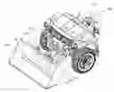
FIG. 1 is a perspective view of the front of a utility vehicle with a loader bucket attached using the front attachment control system according to a preferred embodiment of the invention.
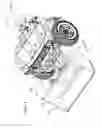
FIG. 2 is a perspective view of the front of a utility vehicle with a snow blower attached using the front attachment control system according to a preferred embodiment of the invention.
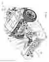
FIG. 3 is a perspective view of a front attachment control system with a snow blower having the angling function, according to a preferred embodiment of the invention.
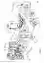
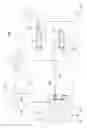
FIG. 4 is a schematic diagram of a hydraulic circuit of a front attachment control system that directs hydraulic fluid to the tilt cylinder according to a preferred embodiment of the invention.
FIG. 5 is a schematic diagram of a hydraulic circuit of a front attachment control system that directs hydraulic fluid to the angling cylinder according to a preferred embodiment of the invention.
DESCRIPTION OF THE PREFERRED EMBODIMENT
In the embodiment shown in FIGS. 1-2, utility vehicle 100 is shown having front attachment control system 101. The utility vehicle may be any off road or work vehicle equipped with front hitch 103 at the front of the vehicle, including recreational vehicles, but the invention also may be used on work vehicles such as small tractors. The utility vehicle's front hitch 103 may include lift frame 104, tilt frame 106, hydraulic lift cylinder 108 and hydraulic tilt cylinder 110. The hydraulic lift cylinder may be connected between lift frame 104 and lift arm 134, and may pivot on a generally horizontal lift pivot axis 136 as shown in FIG. 3. The hydraulic tilt cylinder may be connected between tilt frame 106 and tilt arm 138 shown in FIG. 3, and may pivot on a generally horizontal tilt pivot axis 140.
In the embodiment of FIG. 1, loader bucket 102 is installed on the front hitch of the utility vehicle. Front attachments or implements such as loader buckets and pallet forks may be lifted and tilted during their use. In the embodiment of FIG. 2, snow blower 109 is installed on the front hitch. Front attachments or implements such as snow blowers, blades and brooms may be lifted and also have an angling function instead of a tilt function. Additionally, front attachments or implements such as a snow blower or rotary broom may be driven by a front power take off shaft (PTO) 142.
As shown in FIG. 2, hydraulic angling cylinder 112 may be mounted to a front attachment or implement, such as snow blower 109. For example, hydraulic angling cylinder 112 may be configured to pivot the implement itself or a portion of the implement such as the snow blower discharge chute 111.
Now referring to FIG. 3, one embodiment of the front attachment control system 101 is shown in more detail. Front attachment control system 101 may include diverter valve 114, diverter switch 120, and diverter switch actuator 122. Diverter valve 114 may be a hydraulic valve mounted at the front of the utility vehicle, such as on or adjacent front hitch 103, and may have a pair of ports 124 for connecting hydraulic lines 118 of a front attachment with an angling function such as snow blower 109. For example, hydraulic quick couplers may be used to connect hydraulic lines 118 to ports 124 of diverter valve 114. Diverter valve 114 also may be connected by hydraulic lines 125 to tilt cylinder 110, and hydraulic lines 126 from SCV valve 117 as shown in FIGS. 4-5.
In one embodiment, diverter valve 114 may move to either a first or tilt position, or a second or angling position. FIG. 4 shows diverter valve 114 in a first or tilt position directing hydraulic fluid to tilt cylinder 110. FIG. 5 shows diverter valve 114 in a second or angling position directing hydraulic fluid to angling cylinder 112. In the second or angling position, the front attachment control system may lock the tilt cylinder to prevent inadvertent actuation of the tilt cylinder. Pilot check valve 155 may be provided in the hydraulic lines to the tilt cylinder.
In the embodiment of FIG. 3, diverter valve 114 may be actuated electrically by diverter switch 120, to move the diverter valve to either the first or tilt position or the second or angling position. Diverter switch 120 may be a push button switch in an electrical circuit connected to diverter valve 114. For example, FIG. 4 shows diverter switch 120 closed with the diverter valve in the first or tilt position, and FIG. 5 shows diverter switch 120 open with the diverter valve in the second or angling position.
In one embodiment, actuator 122 may contact and engage diverter switch 120 when hydraulic lines 118 are connected to the diverter valve of the front attachment control system. Actuator 122 may be positioned on or adjacent hydraulic lines 118. When hydraulic lines 118 are connected, actuator 122 may contact and engage diverter switch 120, causing the switch to open and the diverter valve to move to the second or angling position. For example, actuator 122 may include actuator pin 127 that may be guided through a hole or slot into contact with diverter switch 120. When hydraulic lines 118 are disconnected from the diverter valve, actuator 122 is out of contact with diverter switch 120 and does not engage the diverter switch, so the diverter switch may close and the diverter valve may be biased to return to the first or tilt position.
Alternatively, the front attachment control system of the present invention also may use various different actuators to actuate a diverter switch and move diverter valve 114 from the first or tilt position to the second or angling position. For example, other actuators for the diverter switch may include electrical sensors that detect hydraulic lines on a front implement having the angling function, and actuate the diverter switch. The front attachment control system contemplates any type of sensor providing a signal to a diverter switch and diverter valve when a front attachment or implement with the angling function is installed on the front hitch of a utility vehicle.
Now referring to 4-5, in one embodiment, front attachment control system 101 may include SCV valve 117. SCV valve 117 may have first spool valve 130 directing hydraulic fluid to hydraulic lift cylinder 108 through hydraulic lines 133, and second spool valve 132 directing hydraulic fluid to diverter valve 114 through hydraulic lines 126, which then directs hydraulic fluid to either the tilt cylinder 110 or angling cylinder 112. FIG. 4 shows diverter valve 114 directing hydraulic fluid to tilt cylinder 110, and FIG. 5 shows diverter valve 114 directing hydraulic fluid to angling cylinder 112. SCV valve 117 may be operated using joystick 116 in the operator station of the utility vehicle as shown in FIGS. 1-2, which the operator may move fore and aft for the lift cylinder, and left to right for either the tilt cylinder or angling cylinder. Thus, the operator may use the same joystick for tilt and angling functions, as well as the lift function. SCV valve 117 also may be connected to hydraulic pump 128, tank or sump 150, and power beyond port 152. SCV valve 117 also may include pressure relief valve 153.
Having described the preferred embodiment, it will become apparent that various modifications can be made without departing from the scope of the invention as defined in the accompanying claims.
Claims
1. A front attachment control system, comprising:
a diverter valve and a diverter switch on a front of a utility vehicle; and
an actuator on a front attachment having an angling cylinder; the actuator actuating the diverter switch when the front attachment is connected to the front hitch and the diverter switch moves the diverter valve from a first position operating a tilt cylinder to a second position operating the angling cylinder.
2. The front attachment control system of claim 1 wherein the actuator is connected to a hydraulic line of the front attachment.
3. The front attachment control system of claim 1 further comprising a selective control valve connected to the diverter valve that directs hydraulic flow to a lift cylinder and the tilt cylinder or the angling cylinder based on the position of an operator controlled joystick.
4. The front attachment control system of claim 1 further comprising a power take off connected to the front attachment.
5. A front attachment control system, comprising:
a front attachment with an angling cylinder; and
a hydraulic circuit directing hydraulic fluid to a lift cylinder and a tilt cylinder, or to the lift cylinder and the angling cylinder instead of the tilt cylinder if a diverter switch is actuated by connecting the front attachment with the angling cylinder to the hydraulic circuit.
6. The front attachment control system of claim 5 wherein the hydraulic circuit includes a selective control valve operated by a joystick, and a diverter valve actuated by the diverter switch.
7. The front attachment control system of claim 6 wherein the diverter valve is mounted adjacent a front hitch of a utility vehicle.
8. A front attachment control system, comprising:
a selective control valve controlled by a joystick in a utility vehicle operator station;
a diverter valve connected to the selective control valve and having a diverter switch that switches the diverter valve between a first position for an attachment tilt function and a second position for an attachment angling function controlled by the joystick; and
a front attachment with an angling cylinder, a pair of hydraulic lines connectable to the diverter valve, and an actuator that engages the diverter switch as the hydraulic lines are connected to the diverter valve to switch the diverter valve to the second position.
9. The front attachment control system of claim 8 wherein the selective control valve includes a lift function controlled by the joystick.
10. The front attachment control system of claim 8 wherein the actuator is attached to the hydraulic lines of the front attachment with an angling cylinder.
11. The front attachment control system of claim 8 further comprising a front hitch with a power take off.
Images & Drawings included:

Sources:
- United States Patent and Trademark Office - verify current appl. status at the USPTO↗
Similar patent applications:
Recent applications in this class:
- » 20250146256 2025-05-08
METHOD FOR CONTROLLING WORKING MACHINE AND WORKING MACHINE - » 20240003118 2024-01-04
ELECTRO-HYDRAULIC CONTROLLED EXCAVATOR TRAVEL TO TOOL CONTROL PRIORITY FUNCTION - » 20220106770 2022-04-07
HYDRAULIC-PUMP FLOW-RATE CALIBRATION SYSTEM - » 20210348364 2021-11-11
Device for conducting hydraulic fluid - » 20210317634 2021-10-14
Hydraulic arrangement - » 20210010238 2021-01-14
Power mode recommendation system for construction machine - » 20200318318 2020-10-08
Power system for a work machine - » 20200240113 2020-07-30
Control method for hydraulic system in work machine - » 20200040553 2020-02-06
Control device for hydraulic machine - » 20190345692 2019-11-14
Construction machine
Recent applications for this Assignee:
- » 20250293616 2025-09-18
MULTI-OBJECTIVE DESIGN OPTIMIZATION METHOD FOR AUXILIARY RESONANT COMMUTATED POLE INVERTER - » 20250277526 2025-09-04
SEAL TO BE DISPOSED BETWEEN A STRUCTURAL COMPONENT AND AN ENVIRONMENT MODULE - » 20250276564 2025-09-04
WINDOW ASSEMBLIES HAVING TWO OR MORE OPEN CONFIGURATIONS - » 20250261575 2025-08-21
PATH PLANNING - » 20250243831 2025-07-31
FUEL DELIVERY SYSTEM AND METHOD FOR SPARK IGNITED ENGINES OF WORK VEHICLES - » 20250241227 2025-07-31
DUAL FRAME MOUNTED FERTILIZER OPENER WITH INDIVIDUAL DOWNFORCE AND TRAVEL - » 20250221343 2025-07-10
ACTIVE RETURN TUBE AND METHOD OF CONTROLLING SAME - » 20250218232 2025-07-03
SYSTEM AND METHOD FOR COMMUNICATION OF AUTOMATED CONTROL SYSTEM DIAGNOSTICS - » 20250206237 2025-06-26
QUICK RELEASE MOBILE DEVICE HOLDER - » 20250201042 2025-06-19
DIAGNOSTIC TROUBLE CODE DEVICE LINK