Power-saving communication system having leaky transmission lines and amplifiers to extend wireless coverage and power control unit included therein
US20160066069A1
2016-03-03
14/785,021
2013-04-19
✅ Patent granted
US 9,936,270 B2
2018-04-03
WO; PCT/CN2013/074410; 20130419
WO; WO2014/169474; 20141023
Ryan Sherwin
Coats & Bennett, PLLC
2033-10-30
Abstract:
The present disclosure discloses a communication system and a power control unit included therein. The communication system comprises a signal source, one or more amplifiers, one or more terminators and leaky transmission lines. The signal source is configured to provide communication signals. The one or more amplifiers are configured to amplify incoming communication signals. The one or more terminators configured to terminate communication signals. The leaky transmission lines are disposed in correspondence with sections of a elongated area and connect the signal source to each of the one or more terminators via at least one of the amplifiers. The communication system further comprises sensors and the power control unit. Each of the sensors is positioned in correspondence with one of the amplifiers and the terminators and configured to sense whether a vehicle approaches said one of the amplifiers and the terminators. The power control unit is configured to receive sensing results from the sensors and to control each of the amplifiers to amplify its incoming communication signals to a normal power level Pnormal or a power level lower than Pnormal based on the received sensing results.
Assignee:
- TELEFONAKTIEBOLAGET LM ERICSSON (PUBL) 17,237 🇸🇪 Stockholm, Sweden
Applicant:
Interested in similar patents?
Get notified when new applications in this technology area are published.
Classification:
H01Q13/20 » CPC further
Waveguide horns or mouths; Slot antennas; Leaky-waveguide antennas; Equivalent structures causing radiation along the transmission path of a guided wave Non-resonant leaky-waveguide or transmission-line antennas; Equivalent structures causing radiation along the transmission path of a guided wave
H03G3/20 » CPC further
Gain control in amplifiers or frequency changers without distortion of the input signal Automatic control
H04W16/18 » CPC further
Network planning, e.g. coverage or traffic planning tools; Network deployment, e.g. resource partitioning or cells structures Network planning tools
H04W52/02 IPC
Power management, e.g. TPC [Transmission Power Control], power saving or power classes Power saving arrangements
H04W52/0203 » CPC further
Power management, e.g. TPC [Transmission Power Control], power saving or power classes; Power saving arrangements in the radio access network or backbone network of wireless communication networks
H04Q2209/883 » CPC further
Arrangements in telecontrol or telemetry systems; Arrangements in the sub-station, i.e. sensing device; Providing power supply at the sub-station where the sensing device enters an active or inactive mode
H04Q9/00 » CPC main
Arrangements in telecontrol or telemetry systems for selectively calling a substation from a main station, in which substation desired apparatus is selected for applying a control signal thereto or for obtaining measured values therefrom
H01Q1/3225 » CPC further
Details of, or arrangements associated with, antennas; Adaptation for use in or on movable bodies; Adaptation for use in or on road or rail vehicles characterised by the application wherein the antenna is used Cooperation with the rails or the road
H01Q13/206 » CPC further
Waveguide horns or mouths; Slot antennas; Leaky-waveguide antennas; Equivalent structures causing radiation along the transmission path of a guided wave; Non-resonant leaky-waveguide or transmission-line antennas; Equivalent structures causing radiation along the transmission path of a guided wave Microstrip transmission line antennas
G08C19/04 IPC
Electric signal transmission systems in which the signal transmitted is magnitude of current or voltage using variable resistance
H01Q1/32 IPC
Details of, or arrangements associated with, antennas; Adaptation for use in or on movable bodies Adaptation for use in or on road or rail vehicles
H01P1/24 » CPC further
Auxiliary devices Terminating devices
Description
TECHNICAL FIELD
The present disclosure generally relates to the technical field of wireless communication systems, and particularly, to a power-saving communication system having leaky transmission lines and amplifiers to extend wireless coverage and a power control unit included therein.
BACKGROUND
This section is intended to provide a background to the various embodiments of the technology described in this disclosure. The description in this section may include concepts that could be pursued, but are not necessarily ones that have been previously conceived or pursued. Therefore, unless otherwise indicated herein, what is described in this section is not prior art to the description and/or claims of this disclosure and is not admitted to be prior art by the mere inclusion in this section.
In order for wireless systems to provide wireless coverage for elongated areas in a cost-effective manner, leaky transmission lines such as leaky coaxial cables have been proposed and widely deployed as a supplement to the basic wireless network infrastructure.
In contrast with an ordinary transmission line whose outer conductor is specially designed for minimizing electromagnetic radiation, a leaky transmission line has openings deliberately arranged on its outer conductor. Via these openings, electromagnetic waves may leak out of the leaky transmission line to provide wireless coverage for an elongated area along the leaky transmission line.
As elongated areas in the real world (such as expressways, railways and tunnels, etc.) are typically much longer than any single leaky transmission line and signals undergo significant attenuation while travelling along leaky transmission lines, amplifiers are often used with leaky transmission lines to construct a transmission network covering an entire elongated area.
Two typical topologies of networks consisted of leaky transmission lines and amplifiers are respectively illustrated in FIGS. 1-2 and will be described in the following.
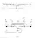
Referring to FIG. 1, a so-called cascade structure is illustrated, which includes a signal source 110, two leaky transmission lines 140 and 141 coupled via a amplifier 121 and a terminator 130. The signal source 110 provides communication signals compliant with any known or heretofore unknown wireless networks and couples the communication signals into the leaky transmission line 140 in a wired manner. After transmitted through the leaky transmission line 140, the communication signals are amplified at the amplifier 120 and then fed into the leaky transmission line 141. After transmitted through the leaky transmission line 141, the communication signals are terminated at the terminator 130.
As a straightforward extension of the cascade structure illustrated in FIG. 1, a cascade of three or more leaky transmission lines can be formed to connect the signal source 110 to the terminator 130, with more than one amplifiers concatenated therebtween. To prevent the quality of transmitted communication signals from being significantly deteriorated by noise accumulation and nonlinear product due to concatenation of too many amplifiers, the number of concatenated amplifiers is normally limited to be less than 3.
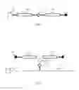
FIG. 2 illustrates a so-called T structure, which includes a signal source 110, an amplifier 120, two terminals 130 and 131, two leaky transmission lines 140 and 141, a divider 150 and a long distance transmission line 160. The signal source 110 supplies communication signals onto the long distance transmission line 160. The amplifier 120 receives and amplifies the communication signals carried on the long distance transmission line 160, and supplies the amplified communication signals into both of the leaky transmission lines 140 and 141 via the divider 150. After transmitted through the leaky transmission lines 140 and 141, the amplified communication signals are terminated at the terminators 130 and 131, respectively.
By using an optical fiber as the long distance transmission line 160 and including the amplifier 120 in an optical repeater, the T structure as shown in FIG. 2 is suitable to be used in connection with optical fiber distribution systems.
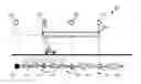
In practical implementations, the cascade structure and the T structure can be combined as needed to form more complex topologies. One example of combinations of the cascade structure and the T structure is presented in FIG. 3. As illustrated, a signal source 110, a long distance transmission line 160, an amplifier 120, a divider 150 and two leaky transmission lines 141 and 142 constitute a T structure. From the leaky transmission line 141, a cascade structure consisted of an amplifier 121, a leaky transmission line 140 and a terminator 130 is extended as one branch of the T structure. From the leaky transmission line 142, a cascade structure comprising the leaky transmission line 142, at least one amplifier 122, at least one leaky transmission line 143 and a terminator 131 is extended as the other branch of the T structure.
In existing communication systems having leaky transmission lines and amplifiers to extend wireless coverage, every amplifier is configured to always amplify its incoming communication signals to a normal power level Pnormal, so that electromagnetic waves leaked from leaky transmission lines disposed in correspondence with sections of an elongated area are strong enough to provide constant wireless coverage for the entire area. As such, whenever a vehicle (such as an automobile, a train, etc.) carrying a user equipment (UE) travels along whichever section of the area, the UE can be provided with wireless service having a satisfactory quality of service (QoS).
Sometimes, however, there may be no vehicle present in some or all sections of the area. In this scenario, it is a waste of power to keep all amplifiers amplifying their incoming communication signals to a normal power level Pnormal and thus provide constant wireless coverage for the entire area.
SUMMARY
In view of the foregoing, there is needed a technique for reducing power consumption in communication systems having leaky transmission lines and amplifiers to extend wireless coverage.
According to a first aspect of the disclosure, there is provided a communication system comprising a signal source, one or more amplifiers, one or more terminators and leaky transmission lines. The signal source is configured to provide communication signals. The one or more amplifiers are configured to amplify incoming communication signals. The one or more terminators configured to terminate communication signals. The leaky transmission lines are disposed in correspondence with sections of a elongated area and connect the signal source to each of the one or more terminators via at least one of the amplifiers. The communication system further comprises sensors and the power control unit. Each of the sensors is positioned in correspondence with one of the amplifiers and the terminators and configured to sense whether a vehicle approaches said one of the amplifiers and the terminators. The power control unit is configured to receive sensing results from the sensors and to control each of the amplifiers to amplify its incoming communication signals to a normal power level Pnormal or a power level lower than Pnormal based on the received sensing results.
According to a second aspect of the disclosure, there is provided the power control unit in the communication system described above.
As certain amplifiers may be controlled to amplify their incoming communication signals to a power level lower than Pnormal based on sensing results from sensors, it is possible to reduce power consumption in communication systems having leaky transmission lines and amplifiers to extend wireless coverage.
BRIEF DESCRIPTION OF THE DRAWINGS
The above and other objects, features, and advantages of the present disclosure will become apparent from the following descriptions on embodiments of the present disclosure with reference to the drawings, in which:
FIG. 1 is a diagram schematically illustrating a cascade structure of a network consisted of leaky transmission lines and amplifiers;
FIG. 2 is a diagram schematically illustrating a T structure of a network consisted of leaky transmission lines and amplifiers;
FIG. 3 is a diagram schematically illustrating a combination of the cascade structure and the T structure;
FIG. 4 is a diagram schematically illustrating an example of a power-saving communication system having leaky transmission lines and amplifiers to extend wireless coverage according to the present disclosure;
FIG. 5 is a diagram schematically illustrating how to control amplifiers to amplify their incoming communication signals based on sensing results from sensors according to an embodiment of the present disclosure;
FIG. 6 is a diagram schematically illustrating how to control amplifiers to amplify their incoming communication signals based on sensing results from sensors according to an embodiment of the present disclosure;
FIG. 7 is a diagram schematically illustrating how to control amplifiers to amplify their incoming communication signals based on sensing results from sensors according to an embodiment of the present disclosure;
FIG. 8 is a diagram schematically illustrating how to control amplifiers to amplify their incoming communication signals based on sensing results from sensors according to an embodiment of the present disclosure;
FIG. 9 is a diagram schematically illustrating how to control amplifiers to amplify their incoming communication signals based on sensing results from sensors according to an embodiment of the present disclosure; and
FIG. 10 is a diagram schematically illustrating how to combine a plurality of the proposed communication systems.
DETAILED DESCRIPTION OF EMBODIMENTS
Hereinafter, the present disclosure is described with reference to embodiments shown in the attached drawings. However, it is to be understood that those descriptions are just provided for illustrative purpose, rather than limiting the present disclosure. Like reference numerals are used throughout the description and several views of the drawings to indicate like or corresponding parts to the extent feasible.
FIG. 4 illustrates an example of a power-saving communication system having leaky transmission lines and amplifiers to extend wireless coverage according to the present disclosure.
As compared with the existing communication system shown in FIG. 3, the proposed power-saving communication system 100 shown in FIG. 4 additionally comprises sensors 170-176 and a power control unit 180.
Each of the sensors 170-176 is positioned in correspondence with one of the amplifiers 120-122 and terminators 130-131, and is configured to sense whether a vehicle approaches the corresponding one of the amplifiers and the terminators.
The sensors may comprise at least one of an acoustic sensor, a visual sensor, a pressure sensor or a vibration sensor. If the proposed power-saving communication system is to be used to provide extended wireless coverage for a road along which cameras have been mounted for traffic monitoring, the cameras for traffic monitoring may be reused as sensors of the proposed power-saving communication system.
The power control unit 180 is configured to receive sensing results from the sensors 170-176 and to control each of the amplifiers 120-122 to amplify its incoming communication signals to a normal power level Pnormal or a power level lower than Pnormal based on the received sensing results.
In a case where an amplifier is controlled to amplify its incoming communication signals to Pnormal, the amplified communication signals can be recovered after transmission through one or more leaky transmission lines receiving the signals, and electromagnetic waves leaked from the one or more leaky transmission lines are strong enough to provide wireless coverage for sections of an elongated area corresponding to the one or more leaky transmission lines.
In one embodiment, the power control unit 180 may comprises a receiving subunit to receive sensing results from the sensors 170-176 and a controlling subunit to control each of the amplifiers 120-122 to amplify its incoming communication signals based on the received sensing results.
With the configuration described above, the power control unit 180 may control some of the amplifiers 120-122 to amplify their incoming communication signals to a power level lower than Pnormal based on sensing results from sensors 170-176. Accordingly, it is possible to reduce power consumption in the communication system 100 having leaky transmission lines and amplifiers to extend wireless coverage.
In the following, several specific embodiments will be given to illustrate how a power control unit may control amplification of amplifiers based on sensing results received from sensors for saving power.
Referring firstly to FIG. 5, the communication system 100 arranged to provide extended wireless coverage for a road includes amplifiers 122-124 concatenated via leaky transmission lines 143 and 144, and the only vehicle traveling along the road is near the amplifier 124.
In this scenario, sensors 173 and 174 may sense that no vehicle approaches their corresponding amplifiers 122 and 123 for a period of time. Receiving these sensing results, the power control unit 180 may control the amplifier 122 to amplify its incoming communication signals to a power level Pidle less than Pnormal, so that the amplified communication signals can be recovered after transmission from the amplifier 122 to its succeeding amplifier 123 through the leaky transmission line 143 while electromagnetic waves leaked from the leaky transmission line 143 are not strong enough to provide wireless coverage for a section of road corresponding to the leaky transmission line 143.
In this manner, power consumption in the system 100 can be reduced as compared with existing systems where all amplifiers constantly amplify their incoming communication signals to Pnormal.
In the scenario shown in FIG. 5, the sensor 175 may sense that a vehicle approaches the amplifier 124. Receiving this sensing result, the power control unit 180 may control the amplifiers 124 and 123 to amplify their incoming communication signals to Pnormal, so that the amplified communication signals can be recovered after transmission through leaky transmission lines 144 and 145, and electromagnetic waves leaked from the leaky transmission lines 144 and 145 are strong enough to provide wireless coverage for sections of road corresponding to the leaky transmission lines 144 and 145.
As such, no matter which direction the vehicle will move along later, it can be provided with wireless service having a satisfactory QoS.
To ensure that no vehicle runs on the section of road corresponding to the leaky transmission line 143 when the amplifier 122 is controlled to reduce its amplified communication signals, the amplifier 122 might be controlled to reduce its amplified communication signals if the power control unit 170 receives sensing results from the sensor 173 indicating that no vehicle approaches the amplifier 122 for a predetermined time which is long than the expected time the vehicle takes to travel from the amplifier 122 to the amplifier 123.
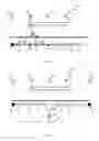
Referring now to FIG. 6, the communication system 100 arranged to provide extended wireless coverage for a road includes a T structure consisted of an amplifier 120, a divider 150 and two leaky transmission lines 141 and 142. One branch of the T structure extending from the leaky transmission line 141 further includes an amplifier 121, a leaky transmission line 140 and a terminator 130. The other branch of the T structure further includes at least one amplifier 122, at least one leaky transmission line 143 and a terminator 131. No vehicle is traveling along the road.
In this scenario, sensors 170-176 may sense that no vehicle approaches their corresponding terminators 130, 131 and amplifiers 120-122 for a period of time. Receiving these sensing results, the power control unit 180 may control the amplifier 120 as the trunk of the T structure not to amplify its incoming communication signals or to amplify its incoming communication signals to a power level Plowest less than Pnormal, so that the amplified communication signals cannot be recovered after transmission from the amplifier 120 through leaky transmission lines 141, 142 receiving the signals and electromagnetic waves leaked from the leaky transmission lines 141, 142 are not strong enough to provide wireless coverage for sections of road corresponding to the leaky transmission lines 141, 142.
In a case where the power control unit 180 receives sensing results from one of sensors 170-176 corresponding to all terminators 130, 131 and amplifiers 120-122 of the T structure indicating that a vehicle approaches one of the terminators 130, 131 and amplifiers 120-122, the power control unit 180 may control the amplifier 120 to amplify its incoming communication signals to Pnormal or Pidle.
Specifically, in a scenario shown in FIG. 7, the power control unit 180 merely receives sensing results from the sensor 171 indicating that a vehicle approaches the amplifier 121. At this point, the power control 180 may control the amplifier 120 to amplify its incoming communication signals to Pnormal and meanwhile control the amplifier 121 to amplify its incoming communication signals to Pnormal. As such, no matter which direction the vehicle will move along later, it can be provided with wireless service having a satisfactory QoS.
In a scenario where the power unit 180 merely receives sensing results from the sensor 170 indicating that a vehicle approaches the terminator 130, the power unit 180 may control the amplifier 120 to amplify its incoming communication signals to Pidle.
Since the amplifier 120 as the trunk of the T structure may be controlled to amplify its incoming communication signals to a power level lower than Pnormal, power consumption in the system 100 can be reduced as compared with existing systems where all amplifiers constantly amplify their incoming communication signals to Pnormal.
FIG. 8 illustrates a scenario where the sensors 170 and 171 sense that no vehicle approaches their corresponding terminator 130 and amplifier 121 for a predetermined time and the amplifier 121 does not constitute a trunk of a T structure. In this case, the power control unit 180 may control the amplifier 121 not to amplify its incoming communication signals or to amplify its incoming communication signals to a power level Plowest less than Pnormal, so that the amplified communication signals cannot be recovered after transmission from the amplifier 121 to the terminator 130 through the leaky transmission line 140 therebetween and electromagnetic waves leaked from the leaky transmission line 140 are not strong enough to provide wireless coverage for a section of the elongated area corresponding to the leaky transmission line 140.
In a scenario where the sensor 170 senses that a vehicle approaches the terminator 130 and the amplifier 121 does not constitute a trunk of a T structure as shown in FIG. 9, the power control unit 180 may control the amplifier 121 to amplify its incoming communication signals to Pnormal.
FIG. 10 illustrates how to combine a plurality of the proposed communication systems to provide a seamless wireless coverage and power control. As shown in the figure, one terminator 130 in the communication system 100 and one terminator 130′ from another communication system 100′ are co-located and share the same sensor 170. As such, when the sensor 170 senses that a vehicle approaches the terminators 130 and 130′, both power control units 180 and 180′ receiving the sensing result may control amplifiers 121 and 121′ to amplify their incoming communication signals to Pnormal.
The present disclosure is described above with reference to the embodiments thereof. However, those embodiments are provided just for illustrative purpose, rather than limiting the present disclosure. The scope of the disclosure is defined by the attached claims as well as equivalents thereof. Those skilled in the art can make various alternations and modifications without departing from the scope of the disclosure, which all fall into the scope of the disclosure.
Claims
1-14. (canceled)
15. A communication system, comprising:
a signal source configured to provide communication signals;
one or more amplifiers configured to amplify incoming communication signals;
one or more terminators configured to terminate communication signals;
leaky transmission lines disposed in correspondence with sections of an elongated area and connecting the signal source to each of the one or more terminators via at least one of the amplifiers;
sensors each positioned in correspondence with one of the amplifiers and the terminators and configured to sense whether a vehicle approaches the one of the amplifiers and the terminators; and
a power control unit configured to receive sensing results from the sensors and to control each of the amplifiers to amplify its incoming communication signals to a normal power level (Pnormal) or a power level lower than Pnormal based on the received sensing results.
16. The communication system of claim 15, wherein, when an amplifier is controlled to amplify its incoming communication signals to Pnormal:
the amplified communication signals can be recovered after transmission through one or more leaky transmission lines receiving the signals, and
electromagnetic waves leaked from the one or more leaky transmission lines are strong enough to provide wireless coverage for sections of the elongated area corresponding to the one or more leaky transmission lines.
17. The communication system of claim 15, wherein at least two amplifiers are concatenated via one or more leaky transmission lines.
18. The communication system of claim 17, wherein, in response to the power control unit receiving sensing results from sensors corresponding to one amplifier among the concatenated amplifiers and its succeeding amplifier indicating that no vehicle approaches either of the amplifiers for a predetermined time, the power control unit controls the one amplifier to amplify its incoming communication signals to a power level Pidle less than Pnormal, so that the amplified communication signals can be recovered after transmission from the one amplifier to its succeeding amplifier through a leaky transmission line therebetween while electromagnetic waves leaked from the leaky transmission line are not strong enough to provide wireless coverage for a section of the elongated area corresponding to the leaky transmission line.
19. The communication system of claim 17, wherein, in response to the power control unit receiving sensing results from a sensor corresponding to one amplifier among the concatenated amplifiers indicating that a vehicle approaches the one amplifier, the power control unit controls the one amplifier and its preceding amplifier to amplify their incoming communication signals to Pnormal.
20. The communication system of claim 15, wherein at least one amplifier has its amplified communication signals supplied into two leaky transmission lines via a divider, the at least one amplifier constituting a trunk of a T structure and two branches of the T structure extending respectively from the two leaky transmission lines.
21. The communication system of claim 20, wherein at least one of the branches of the T structure contains one or more amplifiers.
22. The communication system of claim 20, wherein, in response to the power control unit receiving sensing results from sensors corresponding to all terminators and amplifiers of the T structure indicating that no vehicle approaches any of the terminators and amplifiers for a predetermined time, the power control unit controls the amplifier as the trunk of the T structure not to amplify its incoming communication signals or to amplify its incoming communication signals to a power level Plowest, which is less than Pnormal, so that the amplified communication signals cannot be recovered after transmission from the amplifier through leaky transmission lines receiving the signals and electromagnetic waves leaked from the leaky transmission lines are not strong enough to provide wireless coverage for sections of the elongated area corresponding to the leaky transmission lines.
23. The communication system of claim 20, wherein, in response to the power control unit receiving sensing results from one of sensors corresponding to all terminators and amplifiers of the T structure indicating that a vehicle approaches one of the terminators and amplifiers, the power control unit controls the amplifier as the trunk of the T structure to amplify its incoming communication signals to Pnormal or Pidle.
24. The communication system of claim 15, wherein, in response to the power control unit receiving sensing results from sensors corresponding to a terminator and an amplifier concatenated with the terminator indicating that no vehicle approaches either of the terminator and the amplifier for a predetermined time, wherein the amplifier does not constitute a trunk of a T structure, the power control unit controls the amplifier not to amplify its incoming communication signals or to amplify its incoming communication signals to a power level Plowest, which is less than Pnormal, so that the amplified communication signals cannot be recovered after transmission from the amplifier to the terminator through a leaky transmission line therebetween and electromagnetic waves leaked from the leaky transmission line are not strong enough to provide wireless coverage for a section of the elongated area corresponding to the leaky transmission line.
25. The communication system of claim 15, wherein, in response to the power control unit receiving sensing results from a sensor corresponding to a terminator indicating that a vehicle approaches the terminator, wherein the terminator is concatenated with an amplifier which does not constitute a trunk of a T structure, the power control unit controls the amplifier to amplify its incoming communication signals to Pnormal.
26. The communication system of claim 15, wherein one terminator in the communication system and one terminator from another communication system are co-located and share the same sensor for sensing whether a vehicle approaches the two terminators.
27. The communication system of claim 15, wherein the sensors comprise at least one of:
an acoustic sensor;
a visual sensor;
a pressure sensor; and
a vibration sensor.
28. A power control unit in a communication system, the communication system having a signal source configured to provide communication signals; one or more amplifiers configured to amplify incoming communication signals; one or more terminators configured to terminate communication signals; leaky transmission lines disposed in correspondence with sections of an elongated area and connecting the signal source to each of the one or more terminators via at least one of the amplifiers; and sensors each positioned in correspondence with one of the amplifiers and the terminators and configured to sense whether a vehicle approaches the one of the amplifiers and the terminators; the power control unit comprising:
one or more processing circuits configured to receive sensing results from the sensors and to control each of the amplifiers to amplify its incoming communication signals to a normal power level (Pnormal) or a power level lower than Pnormal based on the received sensing results.
Images & Drawings included:
Sources:
- United States Patent and Trademark Office - verify current appl. status at the USPTO↗
Recent applications in this class:
- » 20250240551 2025-07-24
SETTING DEVICE, SETTING METHOD, AND COMPUTER READABLE RECORDING MEDIUM - » 20250234116 2025-07-17
SYSTEM AND METHOD FOR OBTAINING VEHICLE TELEMATICS DATA - » 20250234115 2025-07-17
POWER TOOL AND METHOD FOR WIRELESS COMMUNICATION - » 20250234114 2025-07-17
Voltage Detection Devices and Safety Headwear Coupling Systems - » 20250203247 2025-06-19
Transmission of Pre-Processed Sensor Data While Incorporating Data Quality - » 20250193559 2025-06-12
COUPLING-INDEPENDENT, REAL-TIME WIRELESS RESISTIVE SENSING THROUGH NONLINEAR PT-SYMMETRY - » 20250159387 2025-05-15
ORAL CARE MONITORING AND HABIT FORMING FOR CHILDREN - » 20250159386 2025-05-15
SYSTEMS AND METHODS OF SECURE COMMUNICATION OF DATA FROM MEDICAL DEVICES - » 20250142234 2025-05-01
Method and apparatus for local sensing - » 20250133310 2025-04-24
SYSTEM AND METHOD FOR EXTENDING THE FUNCTIONALITY OF A FIRST TRANSMITTER
Recent applications for this Assignee:
- » 20250294537 2025-09-18
NETWORK DEPLOYMENT BASED ON PARTIALLY OVERLAPPED CARRIERS - » 20250294375 2025-09-18
CONTROLLING THE COLLECTION OF DATA FOR USE IN TRAINING A MODEL - » 20250294304 2025-09-18
RENDERING OF VOLUMETRIC AUDIO ELEMENTS - » 20250294158 2025-09-18
DERIVATION OF A VALUE FOR EACH LAYER REPRESENTATION OF A BITSTREAM - » 20250294075 2025-09-18
DEVICES AND METHODS FOR PROVISION OF RESOURCE REPRESENTATIONS - » 20250286796 2025-09-11
ENHANCED REPORTING OF QUALITY-OF-EXPERIENCE (QOE) MEASUREMENTS - » 20250285628 2025-09-11
SUPPORT FOR GENERATION OF COMFORT NOISE, AND GENERATION OF COMFORT NOISE - » 20250280258 2025-09-04
SEAMLESS RENDERING OF AUDIO ELEMENTS WITH BOTH INTERIOR AND EXTERIOR REPRESENTATIONS - » 20250279952 2025-09-04
METHOD AND SYSTEM FOR WORKLOAD MANAGEMENT OF NFV-MANO FUNCTIONAL ENTITIES - » 20250279872 2025-09-04
METHODS AND APPARATUSES FOR UPLINK TRANSMISSION