Backstopping break system (BBS) for manual transmission automobiles
US20160075314A1
2016-03-17
14/485,785
2014-09-14
✅ Patent granted
US 9,694,792 B2
2017-07-04
-
-
Nicholas J Lane
Azadeh Saidi
2035-01-02
Abstract:
Backstopping Brake System (BBS) is a part with two original and Accessory natures that can be installed on all manual transmission cars which their engine power is transmitted into forward wheels. By installing the system on vehicle forward wheels axle (plus (P)), when plus rotates around its axle in a reverse motion of engine, it locks the plus (P) and prevents unnecessary reverse motion of vehicle. This system can be activated or inactivated from cabin inside wirelessly through control remote system (2-3) or by wire. In the case of necessary reverse motion, this system is inactivated by pulling back its pawl. For safety, when vehicle has a severe shock, this system will be separated from joint point of vehicle body.
Applicant:
Interested in similar patents?
Get notified when new applications in this technology area are published.
Classification:
B60T7/122 » CPC main
Brake-action initiating means for automatic initiation; for initiation not subject to will of driver or passenger for locking of reverse movement
B60T7/12 IPC
Brake-action initiating means for automatic initiation; for initiation not subject to will of driver or passenger
F16D41/12 » CPC further
Freewheels or freewheel clutches with hinged pawl co-operating with teeth, cogs, or the like
B60T1/005 » CPC further
Arrangements of braking elements, i.e. of those parts where braking effect occurs specially for vehicles by locking of wheel or transmission rotation
F16D2500/10493 » CPC further
External control of clutches by electric or electronic means; System to be controlled; Clutch; Clutch type One way clutch
F16D48/06 » CPC further
External control of clutches Control by electric or electronic means, e.g. of fluid pressure
B60T2201/06 » CPC further
Particular use of vehicle brake systems; Special systems using also the brakes; Special software modules within the brake system controller Hill holder; Start aid systems on inclined road
F16D2500/50841 » CPC further
External control of clutches by electric or electronic means; Problem to be solved by the control system; Relating driving conditions Hill hold
B60T1/00 IPC
Arrangements of braking elements, i.e. of those parts where braking effect occurs specially for vehicles
F16D41/14 » CPC further
Freewheels or freewheel clutches with hinged pawl co-operating with teeth, cogs, or the like the effective stroke of the pawl being adjustable
Description
SUMMARY OF INVENTION
This invention is a solution for improvement driving enjoyment and safety for low skilled drivers in places that have three following characteristics:
-
- 1) Multiplicity of steep vehicle passages
- 2) Heavy traffic in vehicle passages
- 3) Safety distance nonconformity by drivers
This system can be used on vehicles that are equipped with manual transmission gearbox and it is installed on forward wheels axle as a side part (accessory) instead of lying in gearbox mechanism.
This invention has been designed to improve driving enjoyment and safety for low skilled drivers that have to drive in steep and heavy traffic vehicle passages that safety distance is not conformed by back vehicle. Low skill drivers have difficulties in every stop by having concern about probable reverse motion of vehicle face up to a problem in controlling their vehicles and are always worried during the path. This system after activation prevents unwanted rollback of vehicle. So the driver by having confidence about this matter passes the acclivity simply.
This system not only can be installed on vehicles in factory originally but also it can be installed as a vehicle side part (accessory) that has no interference in any systems of vehicle and there is no need to open any part. For safety, when vehicle has a severe shock, if this system makes disorder in vehicle forward motion, it will be separated from joint point of vehicle body and rotates accompanied with plus to keep vehicle safe.
This system has been designed as a clamp which is located around plus and for installation there is no need to remove any part of the car. Also it has been designed in a way that is installed very quickly (based on vehicle type maximum 10 minutes). Meanwhile, it can be installed on all vehicles equipped with manual gearbox which their motor power is exerted to forward wheels.
According to weight of the vehicle (V), the material selection depends on loads and stresses produced by the resistance force against the weight of the vehicle. So it is obviously that material selection includes large variety ferrous alloys to Plastic and etc.
BRIEF DESCRIPTION OF DRAWINGS
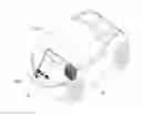
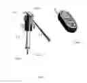
FIG. 1 shows the location of BBS, battery and remote control in vehicle accompanied with their numbers.
FIG. 2 shows two main sections of BBS including ratchet system and control system accompanied with their numbers.
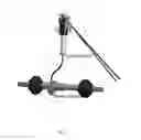
FIG. 3 shows different parts of ratchet system accompanied with their numbers.
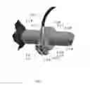
FIG. 4 shows different parts of control system accompanied with their numbers.
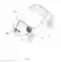
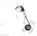
FIG. 5 shows all components of BBS including ratchet system and control system installed on plus axle accompanied with their numbers.
DETAILED DESCRIPTION
This invention is consisted of two main sections; that will be explained later:
-
- Ratchet System (1)
- Control system (2)
Ratchet System (1)
This system is a ratchet that is comprised of wheel (1-1) and pawl (1-2). Wheel (1-1) is located on vehicle plus (P) and it is fixed by sticking (S) via some kind of adhesive or is welded thereto. Sticking point has been specified in FIG. 5. When BBS is manufactured as an original part by automaker, wheel (1-1) can be located on plus (P) axle as a piece in manufacturing phase.
Wheel (1-1)
Wheel (1-1) includes two semicircle clamps, (1-1-A) and (1-1-B) that are located as clamps on plus (P) axle and are fixed by special sticking.
Pawl (1-2)
When wheel (1-1) moves inversely (Counter Clockwise), pawl (1-2) gets stuck in wheel cogs (1-1-T) and causes a brake and therefore prevents backward motion of plus (P). In forward motion (Clockwise), wheel (1-1) will distance wheel cogs (1-1-T) from pawl spontaneously. The power that pushes pawl (1-2) on wheel cogs (1-1-T) can be either from pawl spring (1-2-S) or pawl's (1-2) gravitational power. Pawl (1-2) rotates around pawl pin (1-2-P) that has been fixed on case (1-3).
Pawl's (1-2) rollback, causes BBS inactivation. This action happens through Electro-Mechanical Actuator (2-1).
Case (1-3)
Case (1-3) consists of two semicircles, (1-3-A) that pawl (1-2) and control cable (2-2) are joined to it and it is also connected to (1-3-B) which is a simple semi-cylinder and is connected to (1-3-A) on the other end, and therefore covers the entire wheel (1-1). For exact and quick coupling of two semicircles of case (1-3), two quick clamping springs (1-3-S) are located on contact border of two semicircles that cause quick and instant clamp of two semicircles.
Clamping Joint (1-4)
This joint is a device for clamping two parts of case (1-3). It couples to them and therefore fixes them in place. This can be done either via a spring attachment or screw. Clamping joint (1-4) design is in a way that clamping is too simple and instant for installation. We can use a spring instead of screw to join two parts of case (1-3). In this way installation speed is lower but installation stability is higher.
Holder (1-5)
This part fixes pawl pin (1-2-P) to a rigid point of vehicle structure and stands resistant power against rollback (Rigid point means a place with high value of structural strength which is able to withstand vehicle weight on the slopes). Based on vehicle type, the size and form of this part is different and is in the form of chain or buckle. Also based on vehicle type, joint forms and joint points are different.
Control System (2)
This system undertakes the task of inactivating ratchet system (1) to provide vehicle backward motion (counter clockwise rotation of the vehicle) possibility in necessary situations as reverse motion. Control system has been consisted of following sections:
Electro-Mechanical Actuator (2-1)
This motor provides necessary power to pull back pawl (1-2). Its energy is supplied through Battery (B).
Control Cable (2-2)
This sheathed steel cable (like cars clutch cable) transmits electro-mechanical actuator (2-1) power to pawl (1-2). Using cable mechanism provides the possibility to install actuator (2-1) in various layouts for different vehicle structures without any limitation. This cable is consisted of three sections, sheath (2-2-S), wire (2-2-C) and regulation screws (2-2-R). Sheath (2-2-S) is fixed to the vehicle body. Therefore when vehicle moves forward, friction force between case (1-3) and plus (P) pulls case (1-3) in plus (P) rotation direction. Since cable (2-2) has been fixed to cars main structure, it resists against this motion and is pulled. It causes steel cable/wire (2-2-C) inside sheath (2-2-S) to be pulled back and subsequently causes pawl (1-2) to draw back. As a result, when vehicle moves forward, pawl (1-2) doesn't play/engage on wheel cogs (1-1-T) and it prevents making noise.
To optimize control cable (2-2) function, regulation screws (2-2-R) are located on its two tips, so cable is always pulled with an appropriate value and electro-mechanical actuator (2-1) can control pawl (1-2) motion precisely. Control cable is joined to pawl (1-2) through pin (2-2-P).
Remote Control Kit (2-3)
This kit is controlled through remote control (2-3-R); which controls electro-mechanical motor function (2-1). It provides activation and inactivation possibility of BBS by driver from cabin. This kit is protected inside the remote control kit case (2-3-C).
Control System Stand (2-4)
Stand (2-4) fixes control system (2) on vehicle body in an appropriate place.
This embodiment was simply the best mode of operation of the current invention, it is however obvious to one having ordinary skill in the art that other configurations within the scope of the invention can be utilized to achieve best performance for the invention.
Claims
1. A backstopping brake for manual transmission vehicles system comprising a manual transmission gearbox, a ratchet comprising of at least a wheel and a pawl; wherein said wheel comprises a first and second semicircular clamps located on a plus axle and attached to said plus axle via an attachment means; when said wheel rotates counter clockwise (CCW) said pawl gets stuck in cogs of said wheel and causes a brake and therefore prevents backward motion of said plus; on the other hand when said wheel is rotating forward/clockwise causes said clogs from engaging with said pawl; a control system inactivates said ratchet providing backward motion of said vehicle.
2. The backstopping brake system of claim 1, wherein said attachment means comprises sticking via an adhesive compound or welding.
3. The backstopping brake system of claim 2, wherein said system further comprises an electro mechanical actuator, pulling back said pawl.
4. The backstopping brake system of claim 3, further comprising a control cable, comprising two regulation screws transferring a power of said electro-mechanical actuator to said pawl; therefore when said plus moves forward, said case is pulled in a direction similar to that of said plus; said control cable comprises a sheath pulling back said pawl without any power of said electro-mechanical actuator, therefore preventing any collision/contact between said pawl with said wheel cogs.
Images & Drawings included:
Sources:
- United States Patent and Trademark Office - verify current appl. status at the USPTO↗
Recent applications in this class:
- » 20250121804 2025-04-17
DRIVING ASSISTANCE APPARATUS, DRIVING ASSISTANCE METHOD, AND NON-TRANSITORY STORAGE MEDIUM - » 20230202433 2023-06-29
Rotation restriction control device, rotation restriction device, and vehicle - » 20220258704 2022-08-18
System and method for vehicle stop control - » 20220242376 2022-08-04
Braking control device - » 20220185245 2022-06-16
Hill-hold assist - » 20210380084 2021-12-09
Method and control system for controlling machine - » 20210009093 2021-01-14
Device/method for parking brake assistance - » 20200114885 2020-04-16
Method and system for vehicle control - » 20180319379 2018-11-08
VEHICLE SAFETY BRAKING SYSTEM - » 20180065602 2018-03-08
Electronic control brake system and method for controlling the same