Methods for manufacturing elongated structural elements of composite material
US20160083069A1
2016-03-24
14/856,607
2015-09-17
✅ Patent granted
US 10,449,734 B2
2019-10-22
-
-
John L Goff, II
Meunier Carlin & Curfman LLC
2037-07-15
Abstract:
Methods for manufacturing elongated structural elements are provided. Such methods provide composite material having optimal properties such as weight and strength which can be produced at much lower costs compared to conventional methods. Composite materials including such elements are also provided. In addition, commercial products incorporating such structural elements are provided.
Inventors:
- Gianni IAGULLI 4 🇮🇹 Foggia, Italy
- Giuseppe TOTARO 5 🇮🇹 LUCERA, Italy
- Gianni IAGULLI 11 🇮🇹 SAN SEVERO, Italy
- Giuseppe Totaro 1 🇮🇹 Foggia, Italy
Assignee:
- ALENIA AERMACCHI S.p.A. 7 🇮🇹 Rome, Italy
Applicant:
Interested in similar patents?
Get notified when new applications in this technology area are published.
Classification:
B29C65/002 » CPC further
Joining of preformed parts ; Apparatus therefor Joining methods not otherwise provided for
B64C1/061 » CPC main
Fuselages; Constructional features common to fuselages, wings, stabilising surfaces and the like; Frames; Stringers; Longerons ; Fuselage sections Frames
B64C1/064 » CPC further
Fuselages; Constructional features common to fuselages, wings, stabilising surfaces and the like; Frames; Stringers; Longerons ; Fuselage sections Stringers; Longerons
B64C1/065 » CPC further
Fuselages; Constructional features common to fuselages, wings, stabilising surfaces and the like; Frames; Stringers; Longerons ; Fuselage sections Spars
B29C65/00 IPC
Joining of preformed parts ; Apparatus therefor
B64C1/06 IPC
Fuselages; Constructional features common to fuselages, wings, stabilising surfaces and the like Frames; Stringers; Longerons ; Fuselage sections
B64C3/18 » CPC further
Wings Spars; Ribs; Stringers
B29C66/0042 » CPC further
General aspects of processes or apparatus for joining preformed parts; Preventing sticking together, e.g. of some areas of the parts to be joined of the joining tool and the parts to be joined
B29C33/505 » CPC further
Moulds or cores; Details thereof or accessories therefor with means for, or specially constructed to facilitate, the removal of articles, e.g. of undercut articles with means for collapsing or disassembling elastic or flexible cores or mandrels, e.g. inflatable
B29D99/00 IPC
Subject matter not provided for in other groups of this subclass
B29C66/1122 » CPC further
General aspects of processes or apparatus for joining preformed parts; General aspects dealing with the joint area or with the area to be joined; Particular design of joint configurations particular design of the joint cross-sections; Joint cross-sections comprising a single joint-segment, i.e. one of the parts to be joined comprising a single joint-segment in the joint cross-section; Single lapped joints Single lap to lap joints, i.e. overlap joints
B29C66/1222 » CPC further
General aspects of processes or apparatus for joining preformed parts; General aspects dealing with the joint area or with the area to be joined; Particular design of joint configurations particular design of the joint cross-sections; Joint cross-sections combining only two joint-segments; Tongue and groove joints; Tenon and mortise joints; Stepped joint cross-sections; Joint cross-sections combining only two joint-segments, i.e. one of the parts to be joined comprising only two joint-segments in the joint cross-section comprising at least a lapped joint-segment
B29C66/1224 » CPC further
General aspects of processes or apparatus for joining preformed parts; General aspects dealing with the joint area or with the area to be joined; Particular design of joint configurations particular design of the joint cross-sections; Joint cross-sections combining only two joint-segments; Tongue and groove joints; Tenon and mortise joints; Stepped joint cross-sections; Joint cross-sections combining only two joint-segments, i.e. one of the parts to be joined comprising only two joint-segments in the joint cross-section comprising at least a butt joint-segment
B29C66/131 » CPC further
General aspects of processes or apparatus for joining preformed parts; General aspects dealing with the joint area or with the area to be joined; Particular design of joint configurations particular design of the joint cross-sections; Single flanged joints; Fin-type joints; Single hem joints; Edge joints; Interpenetrating fingered joints; Other specific particular designs of joint cross-sections not provided for in groups - Single flanged joints, i.e. one of the parts to be joined being rigid and flanged in the joint area
B29C66/4344 » CPC further
General aspects of processes or apparatus for joining preformed parts; General aspects of joining substantially flat articles, e.g. plates, sheets or web-like materials; Making flat seams in tubular or hollow articles; Joining single elements to substantially flat surfaces; Joining substantially flat articles ; Making flat seams in tubular or hollow articles; Joining a relatively small portion of the surface of said articles; Joining substantially flat articles for forming corner connections, fork connections or cross connections Joining substantially flat articles for forming fork connections, e.g. for making Y-shaped pieces
B29C66/43441 » CPC further
General aspects of processes or apparatus for joining preformed parts; General aspects of joining substantially flat articles, e.g. plates, sheets or web-like materials; Making flat seams in tubular or hollow articles; Joining single elements to substantially flat surfaces; Joining substantially flat articles ; Making flat seams in tubular or hollow articles; Joining a relatively small portion of the surface of said articles; Joining substantially flat articles for forming corner connections, fork connections or cross connections; Joining substantially flat articles for forming fork connections, e.g. for making Y-shaped pieces with two right angles, e.g. for making T-shaped pieces, H-shaped pieces
B29C66/474 » CPC further
General aspects of processes or apparatus for joining preformed parts; General aspects of joining substantially flat articles, e.g. plates, sheets or web-like materials; Making flat seams in tubular or hollow articles; Joining single elements to substantially flat surfaces; Joining single elements to sheets, plates or other substantially flat surfaces said single elements being substantially non-flat
B29C66/54 » CPC further
General aspects of processes or apparatus for joining preformed parts; General aspects of joining tubular articles; General aspects of joining long products, i.e. bars or profiled elements; General aspects of joining single elements to tubular articles, hollow articles or bars; General aspects of joining several hollow-preforms to form hollow or tubular articles; Joining tubular articles, profiled elements or bars; Joining single elements to tubular articles, hollow articles or bars; Joining several hollow-preforms to form hollow or tubular articles Joining several hollow-preforms, e.g. half-shells, to form hollow articles, e.g. for making balls, containers; Joining several hollow-preforms, e.g. half-cylinders, to form tubular articles
B29C66/63 » CPC further
General aspects of processes or apparatus for joining preformed parts; General aspects of joining tubular articles; General aspects of joining long products, i.e. bars or profiled elements; General aspects of joining single elements to tubular articles, hollow articles or bars; General aspects of joining several hollow-preforms to form hollow or tubular articles Internally supporting the article during joining
B29C66/721 » CPC further
General aspects of processes or apparatus for joining preformed parts characterised by the composition, physical properties or the structure of the material of the parts to be joined; Joining with non-plastics material characterised by the structure of the material of the parts to be joined Fibre-reinforced materials
B29C66/73752 » CPC further
General aspects of processes or apparatus for joining preformed parts characterised by the composition, physical properties or the structure of the material of the parts to be joined; Joining with non-plastics material characterised by the intensive physical properties of the material of the parts to be joined, by the optical properties of the material of the parts to be joined, by the extensive physical properties of the parts to be joined, by the state of the material of the parts to be joined or by the material of the parts to be joined being a thermoplastic or a thermoset characterised by the state of the material of the parts to be joined uncured, partially cured or fully cured the to-be-joined area of at least one of the parts to be joined being uncured, i.e. non cross-linked, non vulcanized the to-be-joined areas of both parts to be joined being uncured
B29C66/81455 » CPC further
General aspects of processes or apparatus for joining preformed parts; General aspects of machine operations or constructions and parts thereof; General aspects of the pressing elements, i.e. the elements applying pressure on the parts to be joined in the area to be joined, e.g. the welding jaws or clamps characterised by the design of the pressing elements, e.g. of the welding jaws or clamps characterised by the constructional aspects of the pressing elements, e.g. of the welding jaws or clamps being a fluid inflatable bag or bladder, a diaphragm or a vacuum bag for applying isostatic pressure
B29C70/342 » CPC further
Shaping composites, i.e. plastics material comprising reinforcements, fillers or preformed parts, e.g. inserts comprising reinforcements only, e.g. self-reinforcing plastics; Shaping operations therefor; Shaping by lay-up, i.e. applying fibres, tape or broadsheet on a mould, former or core; Shaping by spray-up, i.e. spraying of fibres on a mould, former or core and shaping or impregnating by compression, i.e. combined with compressing after the lay-up operation using isostatic pressure
B29D99/0003 » CPC further
Subject matter not provided for in other groups of this subclass Producing profiled members, e.g. beams
B29D99/0014 » CPC further
Subject matter not provided for in other groups of this subclass; Producing wall or panel-like structures, e.g. for hulls, fuselages, or buildings provided with ridges or ribs, e.g. joined ribs
B29C66/8322 » CPC further
General aspects of processes or apparatus for joining preformed parts; General aspects of machine operations or constructions and parts thereof characterised by the movement of the joining or pressing tools; Reciprocating joining or pressing tools Joining or pressing tools reciprocating along one axis
B29L2031/3082 » CPC further
Other particular articles; Vehicles, e.g. ships or aircraft, or body parts thereof; Aircrafts Fuselages
B29L2031/3085 » CPC further
Other particular articles; Vehicles, e.g. ships or aircraft, or body parts thereof; Aircrafts Wings
B29C70/44 IPC
Shaping composites, i.e. plastics material comprising reinforcements, fillers or preformed parts, e.g. inserts comprising reinforcements only, e.g. self-reinforcing plastics; Shaping operations therefor; Shaping or impregnating by compression not applied for producing articles of definite length, i.e. discrete articles using isostatic pressure, e.g. pressure difference-moulding, vacuum bag-moulding, autoclave-moulding or expanding rubber-moulding
B29C33/50 IPC
Moulds or cores; Details thereof or accessories therefor with means for, or specially constructed to facilitate, the removal of articles, e.g. of undercut articles with means for collapsing or disassembling elastic or flexible
B29C33/68 » CPC further
Moulds or cores; Details thereof or accessories therefor; Coatings, e.g. enameled or galvanised ; Releasing, lubricating or separating agents Release sheets
B29C65/02 » CPC further
Joining of preformed parts ; Apparatus therefor by heating, with or without pressure
B29C70/446 » CPC main
Shaping composites, i.e. plastics material comprising reinforcements, fillers or preformed parts, e.g. inserts comprising reinforcements only, e.g. self-reinforcing plastics; Shaping operations therefor; Shaping or impregnating by compression not applied for producing articles of definite length, i.e. discrete articles using isostatic pressure, e.g. pressure difference-moulding, vacuum bag-moulding, autoclave-moulding or expanding rubber-moulding Moulding structures having an axis of symmetry or at least one channel, e.g. tubular structures, frames
B29C66/8122 » CPC further
General aspects of processes or apparatus for joining preformed parts; General aspects of machine operations or constructions and parts thereof; General aspects of the pressing elements, i.e. the elements applying pressure on the parts to be joined in the area to be joined, e.g. the welding jaws or clamps characterised by the composition, by the structure, by the intensive physical properties or by the optical properties of the material constituting the pressing elements, e.g. constituting the welding jaws or clamps characterised by the composition of the material constituting the pressing elements, e.g. constituting the welding jaws or clamps
B29C66/49 » CPC further
General aspects of processes or apparatus for joining preformed parts; General aspects of joining substantially flat articles, e.g. plates, sheets or web-like materials; Making flat seams in tubular or hollow articles; Joining single elements to substantially flat surfaces Internally supporting the, e.g. tubular, article during joining
B29L2031/3076 » CPC further
Other particular articles; Vehicles, e.g. ships or aircraft, or body parts thereof Aircrafts
B29C70/34 IPC
Shaping composites, i.e. plastics material comprising reinforcements, fillers or preformed parts, e.g. inserts comprising reinforcements only, e.g. self-reinforcing plastics; Shaping operations therefor; Shaping by lay-up, i.e. applying fibres, tape or broadsheet on a mould, former or core; Shaping by spray-up, i.e. spraying of fibres on a mould, former or core and shaping or impregnating by compression, i.e. combined with compressing after the lay-up operation
Description
CROSS REFERENCE TO RELATED APPLICATION
This application claims priority to and benefit of Italian Patent Application No. TO2014A000739 (which corresponds to Italian Patent Application No. 102014902294265 under the new numbering system which was introduced in 2015 with the implementation of the IPTO online filing platform) filed Sep. 18, 2014, the contents of which are incorporated by reference in their entirety.
FIELD OF THE INVENTION
The present invention relates to the field of aircraft construction in general and refers more specifically to methods for manufacturing elongated structural elements of composite material, such as wing and empennage spars, fuselage stringers, and beams in general. Methods according to the present invention may be applied to structural elements having at least one node between a flange and a web. More particularly, but not exclusively, the present method may be applied to the manufacture of beams or spars having a cross section in the form of a double T (or H), T, or J, and to co-cured monolithic components having stiffenings with the aforesaid cross sections, such as multi-spar boxes or stiffened panels.
BACKGROUND OF THE INVENTION
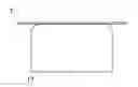
FIG. 11 shows a step in the manufacture of a spar or beam of composite material with a double T cross section, according to a conventional method. The spar is initially assembled in an uncured state, by bringing together the webs of two profiled components 15, 16 with cross sections in the form of opposed C-shapes. Fillers F of carbon fibre and/or structural adhesive, with a pseudo-triangular cross section, are then applied along the longitudinal recesses R which are present along the junction areas between the webs and flanges of the two profiled sections.
Problems have arisen concerning the quality of the junction areas (or “radial” areas) of the spars, owing to the geometrical imprecision of the fresh (uncured) fillers. The imprecision may be due to the filler production process, which is usually carried out by vacuum forming or extrusion. Conventional fillers cannot repeatedly provide the geometrical precision (in terms of radii and thicknesses) specified on the drawings of components which are to be cured on the filler. In other cases, the imprecision may be seen after the step of co-curing with the other components of the spar, with the appearance of wrinkles, accumulations of resin (called “resin pockets”) and fibre distortion. This has led to an increase in rejects, repairs and structural operations in support of the evaluation of the acceptability of the various types of defects encountered.
Moreover, the presence of fillers in the nodes of beams makes it difficult to inspect the radial areas of the spars with ultrasonic methods, since it disperses the signal.
The filler is an integral part of the beam or spar. Its use is dictated by the need to fill the cavity in the junction area to enable the radii of the spars to be compacted correctly during the autoclave curing, which takes place under pressure in vacuum bags. The filler provides a “support” or “reaction” function without which the beam would collapse in the radial area under the action of the pressure of the autoclave and the vacuum bag. The reactive force exerted by the filler also allows correct curing of the C-section profiled components in the radial area, thereby ensuring the absence of porosity.
SUMMARY OF THE INVENTION
The present invention provides methods of manufacturing beams of composite material having an optimal weight, while also avoiding the drawbacks discussed above. More particularly, methods disclosed and claimed herein provide lighter beams for a given structural loading, reducing the direct costs of production (the cost of materials and labour for producing a conventional filler), improving the geometrical quality of the beam in the junction (radial) or node area, simplifying the steps of non-destructive testing, and reducing the non-recurring costs of managing typical defects in the region of the filler.
The present invention is based on the fact that, in structural terms, the filler usually only serves a marginal purpose: the two C-shaped sub-elements are designed to bear the whole of the load specified for the beam, and the filler is therefore an element which essentially provides increased weight.
The aforesaid objects and advantages as well as others, which will be more fully evident from the following text, are achieved according to the present invention described and claimed herein.
To summarize briefly, instead of applying conventional fillers, one or more resilient inserts are inserted into the nodal junction areas between the web and the flanges of an elongated structural element. At the end of the curing (polymerization) step, the inserts are extracted from the cured structural element, leaving cavities extending longitudinally through the respective nodal areas. The structural and functional characteristics of embodiments of methods according to the invention will now be described by reference to the following figures.
BRIEF DESCRIPTION OF THE FIGURES
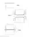
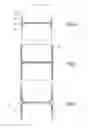
FIGS. 1 to 5 are cross-sectional views which schematically illustrate steps in the assembly of a structural element according to an embodiment of the invention;
FIG. 6 is a cross-sectional view of a structural element according to an embodiment of the invention;
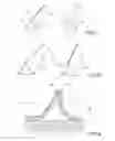
FIGS. 7 and 8 are perspective views which show resilient inserts that can be used to implement manufacturing methods according to certain embodiments of the invention;
FIGS. 9 and 10 are partial schematic views of nodal areas of structural elements manufactured according to an embodiment of the invention; and
FIG. 11 is a schematic cross-sectional view of a step in the assembly of a structural element according to the prior art.
DETAILED DESCRIPTION
Before the detailed explanation of a plurality of embodiments of the invention is given, it must be made clear that the invention is not limited in its application to the details of construction and the configuration of the components presented in the following description or illustrated in the drawings. The invention can be applied in other embodiments and can be used or implemented in different ways in practice.
The methods described below relate to the manufacture of an elongated structural element 10 (FIG. 6), which in this example is a beam or spar. The spar may have a “double T” (or H) cross section, having two parallel flanges 11, 12 and a central web 13 extending at a right angle with respect to the flanges. The double T (or H) shape is not to be interpreted as limiting. More generally, the present methods may be used for manufacturing structural elements elongated in a longitudinal direction, such as beams, spars, stringers, multi-spar boxes, or stiffened panels with cross sections of any shape, provided that they have at least one node or nodal area 14 extending longitudinally along a junction area between a flange and a web.
The web extends in a direction which can form a right angle, or two angles other than 90°, with the flange (or flanges). In the example of FIG. 9, the web 13 extends in a direction which forms two supplementary angles other than 90° with the flange 12. As understood in this text, terms and expressions indicating orientations such as “longitudinal” and “transverse” relate to the longitudinal direction of extension of the elongated structural element (beam, or spar, or stringer, or multi-spar box, or stiffened panel).
In a known preliminary process, two profiled sections of composite material are initially preformed, these sections extending in a longitudinal direction and having C- or U-shaped cross sections. A preliminary step (FIG. 1) may involve the lamination of fabrics T preimpregnated with resin, which are thermoformed on two respective mandrels 17, 18 (FIG. 2), to produce two profiled components 15, 16 having cross sections in the form of opposed C- or U-shapes.
In this embodiment, each profiled section 15, 16 has two parallel flange portions 151, 152 and 161, 162, joined, respectively, to two web portions 153, 163 by means of a respective radiused portion 155, 156 and 165, 166. In each profiled section 15, 16, the parallel flange portions 151, 152 and 161, 162 have respective outer surfaces 154, 157 and 164, 167 facing in transversely opposed directions.
In one embodiment (not shown) of the method, for the manufacture of a structural element with a T-shaped cross section, the profiled sections 15 and 16 may have L-shaped cross sections, including a single flange portion 151, 152 joined, respectively, to a web portion 153, 163 by means of a respective radiused portion 155, 165. The angle formed between the web and the flange may be either 90° or another angle.
The two profiled sections 15, 16 are assembled by bringing their web portions 153, 163 together. The two junctions extending longitudinally to the junctions between the web of the spar and the two flanges are defined as nodal areas or nodes.
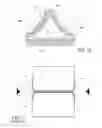
For each nodal area, a respective removable or extractable insert 20 is prepared, having a substantially pseudo-triangular cross section in which an essentially flat base 21 and two other sides 22, 23 can be distinguished, the two other sides converging to form a vertex or apex 24 (FIGS. 3, 7 and 8).
In certain embodiments, the two sides 22, 23 are curved and concave, with curvatures mating with, or corresponding to, the radiused portions of the first 15 and second 16 profiled section. Consequently, the vertex or apex formed at the junction of the curved sides 22, 23 is substantially cusp-shaped (FIGS. 3, 7 and 8).
Two inserts 20 may be prepared for the manufacture of a double T beam which has two nodal areas. The curved sides 22, 23 may have curvatures mating with the respective convex (or radiused) junction surfaces between the web portions and the flange portions of the profiled sections 15, 16.
According to one embodiment of the method, for the manufacture of a beam or spar having its web perpendicular to the flange, the two concave curved sides 22, 23 may be symmetrical about a theoretical plane of symmetry which runs through a mid-line of the base 21 and is perpendicular to the base (FIG. 7).
According to one embodiment, for the manufacture of a beam or spar where the web forms angles other than 90° with the flange, the two concave curved sides 22, 23 are asymmetrical (FIG. 8).
The inserts 20 may be made of resilient material such as pre-cured silicone rubber.
Suitable materials which may be selected for the extractable inserts may include, for example, polysiloxanes (polymerized siloxanes), such as the type known as HTV (High Temperature Vulcanizing), which are vulcanized at high temperatures that cannot be reached during the process of curing the composite materials (carbon resin). Experimental tests conducted by the applicant have demonstrated that excellent results can be achieved by using inserts made of silicone rubber of the vinyl-methyl-polysiloxane (VMQ) type belonging to siloxane group Q according to the ISO 1629 standard (derived from ASTM 1418-79). In this specific case, the elastomer used has the following chemical, physical and mechanical properties which are considered to be optimal: specific weight, 1.200+0.020 g/cm3, Shore A hardness 70+5, minimum breaking strength 8 MPa, minimum breaking strain 250%, minimum tear strength 15 kN/m, compression set sch. 25% at 175° C., 40% maximum. However, these values are not to be interpreted as definitive or limiting and are simply provided as evidence of the excellent properties obtained by methods according to the present invention.
In one embodiment, the extractable insert 20 is produced by extrusion.
In other embodiments, the extractable insert 20 is coated with an outer layer 25 (FIGS. 7 and 8) having properties that facilitate its separation from the cured composite material. The outer layer 25 may be conveniently made of adhesive tape based on PTFE (Teflon) or other release materials acceptable in the specific conditions of the relevant process.
As shown in FIG. 3, the first profiled section 15 and the second profiled section 16 are preassembled together, the web portion 153 of the first profiled section 15 being brought against the web portion 163 of the second profiled section 16. In this condition, the flange portions 151, 152 of the first profiled section 15 extend in opposite directions from the directions in which the flange portions 161, 162 of the second profiled section extend, and lie in pairs in two parallel planes. The radiused portions 155, 156 of the first profiled section 15 may be each adjacent to a respective radiused portion 165, 166 of the second profiled section 16, so as to form, on each of the two opposed longitudinal sides of the profiled sections, a respective recess 26 extending longitudinally along the nodal areas.
The inserts 20 are applied (FIG. 4) along the longitudinal recesses 26. The ridges or apexes 24 are inserted into the innermost areas of the recesses 26, while the flat bases 21 remain facing in opposed outward directions.
According to one embodiment, the inserts 20 may be designed so that their flat bases 21 lie substantially flush with the outer surfaces 154, 164 and 157, 167 of the flange portions 151, 152, 161, 162 of the profiled sections 15 and 16.
If necessary, flat laminated layers of composite material then may be applied (FIG. 5) so as to form two respective bases 27, 28, flat in this example, of the structural element. The layers of the bases 27, 28 may extend to cover the outer surfaces 154, 164 and 157, 167 of the flange portions and the flat bases 21 of the inserts.
In a different embodiment (not shown), for the manufacture of a structural element with a T-shaped cross section, only one base 27 may be provided.
The assembly shown in FIG. 5 then may be enclosed between two flat forming or stamping tools (not shown) for imparting a flat shape to the layers of the bases 27, 28, and can be enclosed in a vacuum bag according to known procedures which will not be described here. The assembly is then transferred to an autoclave and subjected to specified temperature and pressure cycles to cause the curing of the resin present in the composite material.
After the autoclave curing, the cured structural element may be allowed to cool to ambient temperature.
Each insert 20 is then extracted from the spar by simply pulling it from one end; this leaves a longitudinally extending cavity 29 in each nodal area, having the shape and dimensions of the respective insert.
During the curing process, the extractable insert 20 undergoes transverse thermal expansion as a result of the temperature rise. This reversible thermal expansion is stronger than the external compressive forces to which the beam is subjected, represented by the vacuum applied by the vacuum bag and the pressure within the autoclave.
On completion of curing, the structural element is allowed to cool, in order to enable the insert or inserts 20 to contract thermally. Since the contraction of the resilient inserts is greater than the contraction of the cured composite material, it causes the cross section of the cavities 29 formed in the structural element to be slightly wider transversely (by a few tenths of a millimetre) than the transverse dimensions of the respective inserts at ambient temperature; this facilitates the extraction of the rubber insert after curing, avoiding the risk that the insert might remain trapped in the beam. To allow for the aforementioned thermal expansion undergone by the silicone insert during the thermal cycle of curing the composite, at the design stage its cross section is appropriately reduced by a percentage of 4% to 6% of the theoretical cross section which the composite beam is intended to have.
Another effect of the compressive strength of the material of the insert 20, combined with its transverse thermal expansion, is its capacity to consolidate in an optimal way the composite material located between the insert and the external vacuum bag (not shown). This prevents the appearance of defects in the laminated solid (porosity and fibre deviation) and in the geometry of the component (distortion, thickness variation, and resin pockets).
Embodiments of the invention provide monolithic elongated structural elements which are free of filler (“filler-less”) and which have at least one web and at least one flange lying on a given geometric plane, and a nodal area extending along a junction between the web and the flange. The structural element forms a longitudinal cavity which extends longitudinally through the nodal area and has a substantially triangular cross section having a substantially flat first side 291 parallel to the geometric plane on which the flange lies and two convex curved sides 292, 293 with their convexities facing the centre of the cavity 29. The curved sides converge in a vertex 294 which extends in an end area of the web. In certain embodiments, the vertices of the triangular cross section may be rounded.
Exemplary embodiment described up to this point relate to methods of assembly by co-curing, in which a composite laminate is polymerized (“cured”) and simultaneously joined (“bonded”) to one or more components of uncured composite material. All the resins of the composite material and the structural adhesives applied to the interface of the components to be joined together may be polymerized in the same curing step.
Alternative embodiments provide for the form of assembly known by the term “co-bonding”, in which two or more components are joined together, at least one of the components being fully cured, while at least one other component is uncured. Therefore, at least one of the components of the structural element, that is to say the profiled sections 15, 16 and the bases 27, 28, may have been cured previously, while at least one of the other components is uncured.
Both the aforesaid co-curing and co-bonding applications also can be used for incorporating a plurality of stiffeners into composite structural panels.
These methods enable appreciable cost reductions to be achieved, including a reduction in the cost of the material for producing the conventional composite filler (depending on the length of the structural element and the cross section of the filler). A further reduction relates to the cost of the time required to manufacture conventional fillers and of the automatic machinery for their preparation. These savings are due in part to the recyclability of the extractable inserts 20.
These methods provide a considerable reduction in the weight of the finished structural element. Furthermore, the methods improve the geometric tolerances in the radial area in comparison to conventional processes: the radii have a regular curvature and the values of the radius lie within narrow tolerance ranges, with an absence of fibre distortions (wrinkles) in the radial area and accumulations of resin, thereby also simplifying the steps of non-destructive (ultrasonic) inspection (NDI) in the radial areas.
Various aspects and embodiments of methods according to the invention have been described. With the exception of the choice between co-curing and co-bonding, each embodiment may be combined with any other embodiment. Furthermore, the invention is not limited to the embodiments described, but may be modified by a person skilled in the art based on the teachings herein while still falling within the scope of the claims which follow.
Claims
What is claimed is:1. A method of manufacturing a structural element of composite material elongated in a longitudinal direction and having at least one web and at least one flange and a nodal area extending along a junction between the web and the flange, the method comprising the steps of:
providing at least three components of composite material, at least one of which is uncured, wherein the three components include
a first component having at least a flange portion, a web portion and at least one radiused portion joining the flange portion to the web portion,
a second component having at least a flange portion, a web portion and at least one radiused portion joining the flange portion to the web portion,
at least one third component having a flat base;
preassembling the first and second components by bringing the web portion of the first component against the web portion of the second component, in such a way that the flange portions of the first and second components extend in opposite directions and lie in the same plane, and the radiused portions of the first and second components are adjacent and together form a longitudinally extending recess;
providing at least one resilient insert having a substantially triangular or pseudo-triangular cross section with a flat base and two other sides converging into a ridge, wherein said other two sides have shapes mating with the respective radiused portions of the first and the second components;
applying the insert along the recess by inserting the ridge between the radiused portions and placing the flat base in the plane in which the flange portions lie;
applying the at least one third component with the flat base against the portions of the flange of the first and second component and the flat base of the insert;
after vacuum bagging, applying at least one programmed cycle of temperature and pressure in an autoclave to cure the uncured components;
upon completion of the curing step, longitudinally extracting said at least one insert from the structural element, thus obtaining a monolithic elongated structural element which forms at least one cavity extending longitudinally through the nodal area and having a shape corresponding to the shape of the insert.
2. The method of claim 1, wherein said two other sides are concave curved sides having respective curvatures mating with the respective radiused portions of the first and second components.
3. The method of claim 1, wherein the insert comprises pre-cured silicone rubber of the vinyl-methyl-polysiloxane (VMQ) type belonging to siloxane group Q according to the ISO 1629 standard (derived from ASTM 1418-79).
4. The method of claim 1, wherein the insert is produced by extrusion.
5. The method of claim 1, wherein the insert is coated with an outer layer having properties that facilitate its separation from the cured composite material.
6. The method of claim 5, wherein the outer layer which covers the insert comprises adhesive tape based on PTFE (Teflon) or other release material.
7. The method of claim 1, wherein after curing and before the step of extracting the insert, the cured structural element is allowed to cool.
8. A structural element of composite material elongated in a longitudinal direction, comprising:
at least one web;
at least one flange lying in a given geometric plane, and
at least one nodal area extending along a junction between the web and the flange;
wherein the structural element forms a longitudinal cavity which extends longitudinally through the nodal area and has a substantially triangular cross section having
a substantially flat first side parallel to the geometrical plane in which the flange lies, and
two other sides converging in a vertex which extends in an end area of the web.
9. The structural element of claim 8, wherein said two other sides are two convex curved sides with convexities facing toward the center of the cavity.
10. The structural element of claim 8, made either through a co-curing process or a co-bonding process.
11. An aircraft comprising the structural element of claim 8.
Images & Drawings included:
Sources:
- United States Patent and Trademark Office - verify current appl. status at the USPTO↗
Similar patent applications:
Recent applications in this class:
- » 20250121926 2025-04-17
BEADED COMPOSITE STRUCTURAL WEB - » 20240336345 2024-10-10
AERIAL VEHICLE AIRFRAME DESIGN AND MANUFACTURING - » 20240317382 2024-09-26
Beaded composite structural web - » 20240253760 2024-08-01
BLENDED WING BODY AIRCRAFT AIRFRAME AND METHOD OF MANUFACTURE - » 20240217644 2024-07-04
FRAME ASSEMBLY AND METHOD FOR MANUFACTURING FRAME ASSEMBLY - » 20240217643 2024-07-04
FUSELAGE HAVING AN AIR DISTRIBUTION SYSTEM - » 20240208633 2024-06-27
ADDITIVE MANUFACTURED AIRCRAFT STRUCTURE WITH REINFORCEMENTS AND METHOD OF MAKING THE SAME - » 20240199188 2024-06-20
SUPPORT DEVICE AND SUPPORT METHOD - » 20240124117 2024-04-18
STRUCTURAL FRAMEWORK COMPONENTS - » 20240109639 2024-04-04
ADDITIVE MANUFACTURED AIRFRAME STRUCTURE HAVING A PLURALITY OF REINFORCEMENT ELEMENTS
Recent applications for this Assignee:
- » 20160144577 2016-05-26
Method for manufacturing a composite part from a preimpregnated material with a semi-crystalline matrix having an amorphous surface layer - » 20160114538 2016-04-28
Methods of manufacturing single piece multi-spar boxes of composite material in a closed mould - » 20150260637 2015-09-17
Systems and methods for measuring absorbed humidity in a composite material - » 20150226661 2015-08-13
Method for determining the tack of a material - » 20150165699 2015-06-18
Tool and a method for forming and assembling beams of composite material - » 20150114607 2015-04-30
Dual-phase fluid heating/cooling circuit provided with temperature-sensing flow control valves