Method of manufacturing gas turbine engine component from a molybdenum-rich alloy
US20160089722A1
2016-03-31
14/849,644
2015-09-10
✅ Patent granted
US 10,335,857 B2
2019-07-02
-
-
Colleen P Dunn | Rajinder Bajwa
Carlson, Gaskey & Olds, P.C.
2036-12-21
Abstract:
A method for manufacturing a gas turbine engine component from a molybdenum-rich alloy. The method includes the steps of providing a molybdenum powder of at least 50% molybdenum by weight, extruding the molybdenum powder to provide a first shape, forming the first shape to a second shape and forging the second shape to provide a third shape.
Assignee:
- UNITED TECHNOLOGIES CORPORATION 3,722 🇺🇸 Farmington, CT, United States
Applicant:
Interested in similar patents?
Get notified when new applications in this technology area are published.
Classification:
B23K26/00 IPC
Working by laser beam, e.g. welding, cutting or boring
B23K26/352 » CPC further
Working by laser beam, e.g. welding, cutting or boring for surface treatment
B22F2998/10 » CPC further
Supplementary information concerning processes or compositions relating to powder metallurgy Processes characterised by the sequence of their steps
F01D25/005 » CPC further
Component parts, details, or accessories, not provided for in, or of interest apart from, other groups Selecting particular materials
B22F1/00 IPC
Metallic powder; Treatment of metallic powder, e.g. to facilitate working or to improve properties
C22C1/045 » CPC further
Making alloys by powder metallurgy Alloys based on refractory metals
C22C27/04 » CPC further
Alloys based on rhenium or a refractory metal not mentioned in groups or Alloys based on tungsten or molybdenum
C22C32/00 IPC
Non-ferrous alloys containing at least 5% by weight but less than 50% by weight of oxides, carbides, borides, nitrides, silicides or other metal compounds, e.g. oxynitrides, sulfides whether added as such or formed
B22F3/20 » CPC main
Manufacture of workpieces or articles from metallic powder characterised by the manner of compacting or sintering; Apparatus specially adapted therefor ; Presses and furnaces by extruding
C22C32/0005 » CPC further
Non-ferrous alloys containing at least 5% by weight but less than 50% by weight of oxides, carbides, borides, nitrides, silicides or other metal compounds, e.g. oxynitrides, sulfides whether added as such or formed with at least one oxides and at least one of carbides, nitrides, borides or silicides as the main non-metallic constituents
B21J5/002 » CPC further
Methods for forging, hammering, or pressing ; Special equipment or accessories therefor Hybrid process, e.g. forging following casting
C22C1/04 IPC
Making alloys by powder metallurgy
F01D25/00 IPC
Component parts, details, or accessories, not provided for in, or of interest apart from, other groups
F01D5/28 » CPC further
Blades; Blade-carrying members ; Heating, heat-insulating, cooling or antivibration means on the blades or the members; Blades Selecting particular materials; Particular measures relating thereto; Measures against erosion or corrosion
B23K20/10 » CPC further
Non-electric welding by applying impact or other pressure, with or without the application of heat, e.g. cladding or plating making use of vibrations, e.g. ultrasonic welding
F05D2230/22 » CPC further
Manufacture essentially without removing material by sintering
F05D2300/131 » CPC further
Materials; Properties thereof; Metals, alloys or intermetallic compounds; Refractory metals, i.e. Ti, V, Cr, Zr, Nb, Mo, Hf, Ta, W Molybdenum
B21J5/00 IPC
Methods for forging, hammering, or pressing ; Special equipment or accessories therefor
C22F1/18 » CPC further
Changing the physical structure of non-ferrous metals or alloys by heat treatment or by hot or cold working of other metals or alloys based thereon High-melting or refractory metals or alloys based thereon
B22F3/17 » CPC further
Manufacture of workpieces or articles from metallic powder characterised by the manner of compacting or sintering; Apparatus specially adapted therefor ; Presses and furnaces by forging
B22F9/16 » CPC further
Making metallic powder or suspensions thereof using chemical processes
B23H7/00 » CPC further
Processes or apparatus applicable to both electrical discharge machining and electrochemical machining
F23R2900/00018 » CPC further
Special features of, or arrangements for continuous combustion chambers; Combustion processes therefor Manufacturing combustion chamber liners or subparts
Description
CROSS-REFERENCE TO RELATED APPLICATIONS
This application claims priority to U.S. Provisional Application No. 62/055,680, which was filed on Sep. 26, 2014 and is incorporated herein by reference.
BACKGROUND
This disclosure relates to a method of manufacturing a gas turbine engine component from a molybdenum-rich alloy.
A gas turbine engine typically includes a fan section, a compressor section, a combustor section and a turbine section. Air entering the compressor section is compressed and delivered into the combustor section where it is mixed with fuel and ignited to generate a high-speed exhaust gas flow. The high-speed exhaust gas flow expands through the turbine section to drive the compressor and the fan section. The compressor section typically includes low and high pressure compressors, and the turbine section includes low and high pressure turbines.
Portions of the gas turbine engine, particularly the combustor and turbine sections, typically run at temperatures that exceed the melting point of some components. Thermal barrier coatings and cooling fluids have been used to thermally protect the metallic components.
Engine designs continue to push the limits of components in pursuit of higher engine efficiency. As a result, temperatures within the engine continue to increase, requiring development of new component materials and manufacturing processes.
SUMMARY
In one exemplary embodiment, a method for manufacturing a gas turbine engine component from a molybdenum-rich alloy. The method includes the steps of providing a molybdenum powder of at least 50% molybdenum by weight, extruding the molybdenum powder to provide a first shape, forming the first shape to a second shape and forging the second shape to provide a third shape.
In a further embodiment of the above, the molybdenum powder is at least 75% molybdenum by weight.
In a further embodiment of any of the above, the molybdenum powder is in a range of 94-98% molybdenum by weight.
In a further embodiment of any of the above, the molybdenum powder has a diameter in a range of 750-3000 microns (0.030-0.120 inches).
In a further embodiment of any of the above, the molybdenum powder has a diameter in a range of 900-1800 microns (0.036-0.072 inches).
In a further embodiment of any of the above, the molybdenum is in a spherical form. The molybdenum powder includes silica and a non-cubic boron nitride.
In a further embodiment of any of the above, the molybdenum powder is synthesized in an alcohol solution containing boron nitride and silica.
In a further embodiment of any of the above, the powder is compacted to provide a density that is at least 75% of the finished part.
In a further embodiment of any of the above, the extrusion step is performed using forces around 5000 tons/ft2 (480 MPa) and under temperatures in a range of 2500-4000° F. (1370-2200° C.).
In a further embodiment of any of the above, the forging step includes hot isothermal forging.
In a further embodiment of any of the above, the forging step is performed using forces around 5000 tons/ft2 (480 MPa) and under temperatures in a range of 2500-4000° F. (1370-2200° C.).
In a further embodiment of any of the above, the extruding step includes providing an I-beam shaped die opening and extruding the compacted powder through the opening.
In a further embodiment of any of the above, the extruding step includes passing an extruded part through a pair of cylindrical dies.
In a further embodiment of any of the above, the extruded part provides at least a portion of at least one of a combustor, a stator, a blade outer air seal, a turbine exhaust case, an augmenter, a strut, and a high temperature bearing.
In a further embodiment of any of the above, the extruding step includes passing the extruded part from the pair of cylindrical dies through a pair of corrugated dies to provide an airfoil contour on the extruded part.
In a further embodiment of any of the above, the finishing process includes at least one of polishing, EDM, laser machining, ultrasonic machining, electrochemical machining and abrasive vibratory finishing.
In a further embodiment of any of the above, the forming step removes at least 20% of the material as compared to the first shape.
In a further embodiment of any of the above, the finished component is one of a combustor, a stator, a blade outer air seal, a turbine exhaust case, an augmenter, a strut, and a high temperature bearing.
BRIEF DESCRIPTION OF THE DRAWINGS
The disclosure can be further understood by reference to the following detailed description when considered in connection with the accompanying drawings wherein:
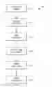
FIG. 1 is a flow chart depicting an example method of manufacturing a gas turbine engine component from a molybdenum-rich alloy.
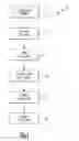
FIG. 2 is a schematic view of a corrugated extrusion process.
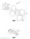
FIG. 3 is a schematic view of a cluster of vanes produced by the process shown in FIG. 2.
The embodiments, examples and alternatives of the preceding paragraphs, the claims, or the following description and drawings, including any of their various aspects or respective individual features, may be taken independently or in any combination. Features described in connection with one embodiment are applicable to all embodiments, unless such features are incompatible.
DETAILED DESCRIPTION
FIG. 1 depicts a method 10 for manufacturing a gas turbine engine component from a molybdenum-rich alloy. Example components include at least portions of a combustor, a stator, a blade outer air seal, a turbine exhaust case, an augmenter, a strut, and a high temperature bearing. The disclosed manufacturing process may be used to make other components as well.
The method 10 includes a step of synthesizing a relatively high purity molybdenum powder, as indicated at block 12. In one example, the molybdenum powder is at least 50% molybdenum by weight. In another example, the molybdenum powder is at least 75% molybdenum by weight, and in another example in a range of 94-98% molybdenum by weight.
In one example, the molybdenum powder provides the molybdenum in a spherical form, which provides homogeneous properties throughout the powder as compared to other forms of molybdenum. In one example, virgin molybdenum powder is around 150 microns (0.006 inches) in diameter. Finished powder can be between 5 and 20 times that size (750-3000 microns; 0.030-0.120 inches). In one example embodiment, the molybdenum powder is 6-12 times the size of virgin powder (900-1800 microns; 0.036-0.072 inches). In one example molybdenum processing approach, the molybdenum is synthesized in an organic compound, such as an alcohol solution containing boron nitride and silica. A solution is processed to strip most of the ceramic using a spray dry process, for example. A very high purity spherical particle molybdenum results, with the balance of the powder including silica and a non-cubic boron nitride. This balance improves the strength of the molybdenum powder.
The powder is consolidated and compacted to provide a density that is at least 75% of the finished part.
The compacted powder is extruded through a die, as indicated at block 14, to provide a first shape corresponding to a very rough component form. One example extrusion process uses forces around 5000 tons/ft2 (480 MPa). Temperatures during the extrusion process are in a range of 2500-4000° F. (1370-2200° C.). In one example, the extrusion process utilizes a screw to force the compacted powder through the die.
Another example extrusion process 114 is shown in FIG. 2. The extrusion process 114 includes a die 30 providing a rough opening 32 through which the compacted powder is extruded. In one example, the rough opening 32 corresponds to an I-beam or H-shape for producing a stator vane having integrated inner and outer platforms. The extruded shape, represented by dashed lines in FIG. 2, passes through a pair of cylindrical die plates 34 before passing through corrugated die plates 36, 38, which provide an airfoil contour. The die plate 36 provides a convex side of the stator vane airfoil, and the die plate 38 provides a concave side of the stator vane airfoil. An example cluster of vanes 40 is shown in FIG. 3. Individual vanes 42 may be separated from the cluster 40 during a trimming step for further processing.
Returning to FIG. 1, the resultant extruded first shape is trimmed, as indicated at block 16. During trimming, the extruded part is sliced into smaller parts that are near 2-5 times the weight of the final designed part. For example, an I-beam extrusion is cut into several inch long pieces with wire EDM or diamond wire sawing.
The trimmed first shape is rough form machined, as indicated at block 18, to provide a second shape that more closely approximates the finished component shape. Rough form machining generates shapes that resemble the final part. Example rough form machining processes include, but are not limited to, grinding, ECM, milling, and ultrasonic machining. The resulting airfoil shape then can be coined or forged to get additional features. During rough form machining the platforms sides and attachment features may be ground. In one example, at least 20-30% of the material as compared to the first shape is removed during the rough forming step.
The second shape is forged by a hot isothermal process, as indicated at block 20, to provide a third shape, which is a near-net shape to the finished part shape. One example forging process uses forces around 5000 tons/ft2 (480 MPa). Temperatures during the forging process are in a range of 2500-4000° F. (1370-2200° C.).
The third shape is finished to provide the finished part. Example finishing processes include polishing, EDM, laser machining, electrochemical machining, ultrasonic machining, abrasive vibratory finishing or other processes, as indicated as block 22.
It should also be understood that although a particular component arrangement is disclosed in the illustrated embodiment, other arrangements will benefit herefrom. Although particular step sequences are shown, described, and claimed, it should be understood that steps may be performed in any order, separated or combined unless otherwise indicated and will still benefit from the present invention.
Although the different examples have specific components shown in the illustrations, embodiments of this invention are not limited to those particular combinations. It is possible to use some of the components or features from one of the examples in combination with features or components from another one of the examples.
Although an example embodiment has been disclosed, a worker of ordinary skill in this art would recognize that certain modifications would come within the scope of the claims. For that reason, the following claims should be studied to determine their true scope and content.
Claims
What is claimed is:1. A method for manufacturing a gas turbine engine component from a molybdenum-rich alloy, the method comprising the steps of:
providing a molybdenum powder of at least 50% molybdenum by weight;
extruding the molybdenum powder to provide a first shape;
forming the first shape to a second shape; and
forging the second shape to provide a third shape.
2. The method according to claim 1, wherein the molybdenum powder is at least 75% molybdenum by weight.
3. The method according to claim 2, wherein the molybdenum powder is in a range of 94-98% molybdenum by weight.
4. The method according to claim 2, wherein the molybdenum powder has a diameter in a range of 750-3000 microns (0.030-0.120 inches).
5. The method according to claim 4, wherein the molybdenum powder has a diameter in a range of 900-1800 microns (0.036-0.072 inches).
6. The method according to claim 1, wherein the molybdenum is in a spherical form, and the molybdenum powder includes silica and a non-cubic boron nitride.
7. The method according to claim 6, wherein the molybdenum powder is synthesized in an alcohol solution containing boron nitride and silica.
8. The method according to claim 1, comprising the step of compacting the powder to provide a density that is at least 75% of the finished part.
9. The method according to claim 1, wherein the extrusion step is performed using forces around 5000 tons/ft2 (480 MPa) and under temperatures in a range of 2500-4000° F. (1370-2200° C.).
10. The method according to claim 1, wherein the forging step includes hot isothermal forging.
11. The method according to claim 10, wherein the forging step is performed using forces around 5000 tons/ft2 (480 MPa) and under temperatures in a range of 2500-4000° F. (1370-2200° C.).
12. The method according to claim 8, wherein the extruding step includes providing an I-beam shaped die opening, and extruding the compacted powder through the opening.
13. The method according to claim 12, wherein the extruding step includes passing an extruded part through a pair of cylindrical dies.
14. The method according to claim 13, wherein extruded part provides at least a portion of at least one of a combustor, a stator, a blade outer air seal, a turbine exhaust case, an augmenter, a strut, and a high temperature bearing.
15. The method according to claim 13, wherein the extruding step includes passing the extruded part from the pair of cylindrical dies through a pair of corrugated dies to provide an airfoil contour on the extruded part.
16. The method according to claim 1, wherein the finishing process includes at least one of polishing, EDM, laser machining, ultrasonic machining, electrochemical machining and abrasive vibratory finishing.
17. The method according to claim 1, wherein forming step removes at least 20% of the material as compared to the first shape.
18. The method according to claim 1, wherein the finished component is one of a combustor, a stator, a blade outer air seal, a turbine exhaust case, an augmenter, a strut, and a high temperature bearing.
Images & Drawings included:
Sources:
- United States Patent and Trademark Office - verify current appl. status at the USPTO↗
Recent applications in this class:
- » 20250001497 2025-01-02
METHODS AND SYSTEMS FOR FORMING PYROTECHNIC MATERIAL EXTRUDATES - » 20240316632 2024-09-26
AUTOGENIC CANISTER FOR METAL RECYCLING BY INDIRECT HOT EXTRUSION - » 20230241677 2023-08-03
Atomized picoscale composition aluminum alloy and method thereof - » 20230150022 2023-05-18
Devices and Methods for Performing Shear-Assisted Extrusion and Extrusion Processes - » 20230113824 2023-04-13
FIBER WITH METAL IONS EXCITED BY LUMINOUS ENERGY AND MANUFACTURING METHOD THEREOF - » 20220410261 2022-12-29
A METHOD OF MANUFACTURING A COMPOSITE COMPONENT WITH VARYING ELECTRIC RESISTIVITY ALONG A LONGITUDINAL DIRECTION - » 20220355374 2022-11-10
Method for manufacturing electrostatic chuck having electrode layer including clad member and electrostatic chuck manufactured thereby - » 20220331861 2022-10-20
Method for manufacturing a lead-free or low lead content brass billet and billet thus obtained - » 20210402471 2021-12-30
Devices and Methods for Performing Shear-Assisted Extrusion and Extrusion Processes - » 20210339314 2021-11-04
PROCESS FOR PRODUCING A MATERIAL COMPOSITE, MATERIAL COMPOSITE AND USE OF THE MATERIAL COMPOSITE AS A HEAT CONDUCTOR AND HEAT EXCHANGER
Recent applications for this Assignee:
- » 20210317743 2021-10-14
Thermally isolated rotor systems and methods - » 20210310363 2021-10-07
Balanced composite root region for a blade of a gas turbine engine - » 20210283681 2021-09-16
Method for removing refractory metal cores - » 20210262415 2021-08-26
High bypass ratio engine bypass duct nozzle with controlled nozzle area - » 20210262400 2021-08-26
Speed limiting for power turbine governing and protection in a turboshaft engine - » 20210262359 2021-08-26
After-fan system with electrical motor for gas turbine engines - » 20210254494 2021-08-19
Vane arm torque transfer plate - » 20210254480 2021-08-19
Tangential rotor blade slot spacer for a gas turbine engine - » 20210254232 2021-08-19
THERMALLY STABLE NICKEL-PHOSPHORUS ALLOY FOR HIGH TEMPERATURE APPLICATIONS - » 20210246838 2021-08-12
Engine control device and methods thereof