Sparse space-time adaptive array architecture
US20160091598A1
2016-03-31
14/867,547
2015-09-28
✅ Patent granted
US 10,054,666 B2
2018-08-21
-
-
Marcus E Windrich
U.S. Naval Research Laboratory | William Ladd
2036-10-10
Abstract:
A sparse multichannel array includes a plurality of array elements, a receiver behind each array element, and a Doppler filter bank behind each receiver, whereby within each Doppler bin is placed spatial nulls at selected angles of undesired interference. The invention enables Doppler processing to be performed on sparse arrays, such as nested or coprime arrays, used in nonlinear adaptive beamforming to mitigate the impact of unintentional interference and hostile jamming on the received signal.
Inventors:
- Peter Vouras 1 🇺🇸 Bristow, VA, United States
- Jean De Graaf 1 🇺🇸 Potomac, MD, United States
Assignee:
- The United States of America, as represented by the Secretary of the Navy 4,501 🇺🇸 Washington, DC, United States
- The Govemment of the United States of America, as represented by the Secretary of the Navy 2 🇺🇸 Washington, DC, United States
Applicant:
Interested in similar patents?
Get notified when new applications in this technology area are published.
Classification:
G01S7/023 » CPC main
Details of systems according to groups of systems according to group Interference mitigation, e.g. reducing or avoiding non-intentional interference with other HF-transmitters, base station transmitters for mobile communication or other radar systems, e.g. using electro-magnetic interference [EMI] reduction techniques
G01S7/02 IPC
Details of systems according to groups of systems according to group
G01S7/36 » CPC further
Details of systems according to groups of systems according to group Means for anti-jamming, e.g. ECCM, i.e. electronic counter-counter measures
G01S7/2813 » CPC further
Details of systems according to groups of systems according to group; Details of pulse systems Means providing a modification of the radiation pattern for cancelling noise, clutter or interfering signals, e.g. side lobe suppression, side lobe blanking, null-steering arrays
G01S13/5244 » CPC further
Systems using the reflection or reradiation of radio waves, e.g. radar systems; Analogous systems using reflection or reradiation of waves whose nature or wavelength is irrelevant or unspecified; Systems using reflection of radio waves, e.g. primary radar systems; Analogous systems; Systems of measurement based on relative movement of target; Discriminating between fixed and moving objects or between objects moving at different speeds using transmissions of interrupted pulse modulated waves based upon the phase or frequency shift resulting from movement of objects, with reference to the transmitted signals, e.g. coherent MTi Adaptive clutter cancellation
G01S7/28 IPC
Details of systems according to groups of systems according to group Details of pulse systems
G01S13/524 IPC
Systems using the reflection or reradiation of radio waves, e.g. radar systems; Analogous systems using reflection or reradiation of waves whose nature or wavelength is irrelevant or unspecified; Systems using reflection of radio waves, e.g. primary radar systems; Analogous systems; Systems of measurement based on relative movement of target; Discriminating between fixed and moving objects or between objects moving at different speeds using transmissions of interrupted pulse modulated waves based upon the phase or frequency shift resulting from movement of objects, with reference to the transmitted signals, e.g. coherent MTi
Description
CROSS-REFERENCE TO RELATED APPLICATIONS
This Application claims the benefit of U.S. Provisional Application 62/055,961, filed on Sep. 26, 2014 and incorporated herein by reference.
FIELD OF THE INVENTION
The invention is directed to a space-time adaptive (STAP) array architecture having a sparse multichannel receiver array, and more particularly to such an array incorporating a Doppler filter bank behind each array element.
BACKGROUND OF THE INVENTION
Adaptive beamforming is a powerful technique used in modern radars to mitigate the impact of unintentional interference and hostile jamming. Typically, nulls are created in the receive pattern of an array by applying a complex weight to each array element. Using conventional linear processing, an array of N physical elements can form no more than N−1 adaptive nulls. To overcome this limitation, nonlinear techniques have been developed capable of forming O(N2) nulls in an array pattern. A drawback to nonlinear adaptive processing is that any Doppler information in the received signal is lost.
To provide a brief overview of nonlinear adaptive processing consider an N element nonuniform linear array (HULA). Assume M narrowband signals arc arriving at this array from directions θ1, θ2, . . . , θM with powers σ12, σ22, . . . , σM2, respectively. Let v(0) be the N-by-1 steering vector corresponding to the direction 0,
v(0)=[1ej(2π/λ)dt sin θ . . . ej(2π/λ)dN1 sin θ]T (1)
where d1 denotes the position of the ith sensor. The received signal at time instant k is
x[k]=A(0)s(k)+n[k] (2)
where A(θ)=[v(θ1) v(θ2) . . . v(θM)] is the array manifold matrix and s[k]=[s1[k] s2[k] . . . sm [k]]T is a vector of samples from uncorrelated signal sources. The noise n[k] is assumed to be temporally uncorrelated so that the signal covariance matrix Rss is diagonal. Now the covariance matrix of the received signal becomes
R zz = E [ xx H ] = A ( 0 ) R ss A ( 0 ) H + σ n 2 I = A ( 0 ) [ σ 1 2 0 … 0 0 σ 2 2 ⋱ ⋮ ⋮ ⋱ ⋱ 0 0 … 0 σ ] A ( 0 ) H + σ n 2 I . ( 3 ) ( 4 )
Next, the covariance matrix Rss is vectorited to create the vector
z ( 0 ) = vcc ( R zz ) = vcc [ ∑ i = 1 M σ i 2 ( v ( θ i ) v ( θ i ) H ) ] + σ n 2 1 n = ( A ( 0 ) * ⊙ A ( 0 ) ) p + σ n 2 1 n ( 5 ) ( 6 )
where * denotes conjugation. p=[σ12 σ22 . . . σM2]T and 1n=[e1T e2T . . . eNT]T with ei a column vector of all zeros except for a one in the ith position. The matrix
A(0)*: A(0)=[v(θ1)*{circle around (•)}v(θ1) . . . v(θM)*{circle around (•)}v(θM)] (7)
is the Khatri-Rao product of the matrices A(θ)* and A(0) with {circle around (•)} denoting the Kronecker product. In conventional nonlinear adaptive processing. the adapted beampattern is formed by applying a weight vector w to the vector z(θ): as in wHz(0). [1]-[3].
A drawback to nonlinear adaptive processing is that any Doppler information in the received signal is lost.
BRIEF SUMMARY OF THE INVENTION
According to the invention, a sparse multichannel array includes a plurality of array elements, a receiver behind each array element, and a Doppler filter bank behind each receiver, whereby within each Doppler bin is placed spatial nulls at selected angles of undesired interference.
The purpose of this invention is to exploit the extra spatial degrees of freedom inherent in nonlinear adaptive processing while also retaining the Doppler information in the received signal. The invention incorporates a Doppler filter bank behind each element of a sparse multichannel array and within each Doppler bin places spatial nulls at the angles of undesired interference.
The invention exploits the extra spatial degrees of freedom inherent in nonlinear adaptive processing while also retaining the Doppler information in the received signal. The invention enables Doppler processing to be performed on sparse arrays, such as nested or coprime arrays, used in nonlinear adaptive beamforming to mitigate the impact of unintentional interference and hostile jamming on the received signal. The invention has applications to Synthetic Aperture Radars (SARs) deployed on Unmanned Aerial Vehicles (UAVs) with severe form factor constraints. Other applications include conventional, legacy radars operating in dense interference environments, and passive sonar systems operating in littoral environments.
BRIEF DESCRIPTION OF THE DRAWINGS
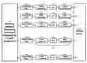
FIG. 1 is a schematic illustration of a multichannel sparse array with a receiver and a Doppler filter bank behind each array element according to the invention; and
FIG. 2 is the adapted angle-doppler response in the 16th Doppler filter (of 32) in a nested array architecture with 6 array elements located at the positions (0,1,2,3,7,11) according to the invention.
DETAILED DESCRIPTION OF THE INVENTION
The invention is illustrated in FIG. 1. It consists of a multichannel sparse array 100 with a receiver 102 and a Doppler filter bank 104 behind each array element 106. Every receiver 102 performs signal downconversion to baseband with downconverter 108, then analog-to-digital conversion with ADC 110, and pulse compression with pulse compressor 112. Each Doppler filter bank 104 transforms the uniformly sampled radar pulses from a single range bin to the Doppler domain. The signal processor 114 then performs nonlinear spatially adaptive processing within each Doppler frequency bin.
To describe the operation of this array architecture consider the discrete-time voltage output vector xn(m,θ) of a sparse (e.g.. nested or coprime) array in the absence of noise.
xn(m,θ)=sn[m]v(0) (8)
where rn denotes pulse number. n corresponds to the range bin. sn(m) represents complex baseband samples of the signal. and v(0) is the steering vector in the direction 0 of a single target. For a fixed range bin n, the Discrete Fourier Transform of xn(m, θ) over K pulses yields the Doppler spectrum
xn(fk, 0)=sn(fk)v(0) (9)
for k=0,1, . . . , K−1. Taking the Kronecker product of xn(fk, 0) in each Doppler bin yields
zk(0)=xn(fk, θ)*{circle around (•)}xn(fk, 0)=|sn(fk)|2(v(0)*{circle around (•)}v(θ)). (10)
After computing an adaptive weight vector wk using any one of a variety of techniques [5]. the spatially adapted pattern in the kth Doppler bin can now he written as
b(fk, 0)=wkHzk(0). k=0, 1 , . . . , K−1 (11)
Notice that the spatial response and the Doppler response of the array are adapted independently. The composite array response b(0) at the nth range bin is formed by summing across all the Doppler filters.
b ( 0 ) = ∑ k = 0 K - 1 w k H z k ( 0 ) . ( 12 )
For the case with L different targets and noise.
x n ( m , 0 ) = [ v ( 0 1 ) v ( 0 2 ) … v ( 0 L ) ] [ s 1 n [ m ] s 2 n [ m ] ⋮ s L n [ m ] ] + [ n 1 n [ m ] n 2 n [ m ] ⋮ n Nn [ m ] ] = A ( 0 ) s n [ m ] + n n [ m ] ( 13 ) ( 14 )
For a fixed range bin n, the Discrete Fourier Transform of xn(m,θ) over K pulses yields
xn(fk, 0)=A(0)sn(fk)+nn(fk) (15)
for k=0,1, . . . , K−1. The vector zk(0) is now
z k ( 0 ) = vcc ( E [ x n ( f k , 0 ) x n ( f k , 0 ) H ] ) = ( A ( 0 ) * ⊙ A ( 0 ) ) p + σ n 2 1 n ( 16 ) ( 17 )
where p=[|s1n(fk)|2 |s2n(fk)|2 . . . |sLn(fk))|2]T. After computing an adaptive weight vector wk, the spatially adapted pattern b(fk, 0) in the kth Doppler bin is given by (11) and the composite array output b(0) is computed as in (12).
FIG. 2 illustrates the adapted angle-doppler response in the 16th Doppler filter (of 32) in a nested array architecture with 6 array elements located at the positions (0,1,2,3,7,11) . There are 7 specified spatial nulls at −52.8°, −40°, −26.4°, −20°, −15.2°, −32.8°, and 47.2° with the mainbeam at 0°. Note that by using linear adaptive beamforming techniques on an array of 6 elements, no more than 5 nulls can be created.
Obviously many modifications and variations of the present invention are possible in the light of the above teachings. It is therefore to be understood that the scope of the invention should be determined by referring to the following appended claims.
Claims
What is claimed as new and desired to be protected by Letters Patent of the United States is:1. A sparse multichannel array, comprising:
a plurality of array elements,
a receiver behind each array element; and
a Doppler filter bank behind each receiver, whereby within each Doppler bin is placed spatial nulls at selected angles of undesired interference.
2. The array of claim 1, wherein the array is selected from nested or co-prime.
3. A sparse multichannel array, comprising:
a plurality of array elements,
a receiver behind each array element, each said receiver comprising:
a downconverter for downconverting a signal to baseband;
an analog-to-digital converter (ADC) to convert baseband to digital; and
a pulse compressor to apply pulse compression to each digital signal; and
a Doppler filter bank behind each receiver, whereby within each Doppler bin is placed spatial nulls at selected angles of undesired interference.
4. The array of claim 3, wherein the array is selected from nested or co-prime.
Images & Drawings included:


Sources:
- United States Patent and Trademark Office - verify current appl. status at the USPTO↗
Recent applications in this class:
- » 20250251487 2025-08-07
RADAR INFORMATION TRANSMISSION METHOD, APPARATUS, AND SYSTEM - » 20250244441 2025-07-31
DOPPLER RADAR COEXISTENCE - » 20250237735 2025-07-24
RF SIGNAL ABSORPTION MODULE - » 20250231273 2025-07-17
RADAR METHOD AND RADAR SYSTEM - » 20250216501 2025-07-03
SYSTEMS AND METHODS MITIGATING POWER FADING - » 20250208253 2025-06-26
METHOD FOR REDUCING INTERFERENCE EFFECTS IN A RADAR SYSTEM - » 20250199112 2025-06-19
INTERFERENCE SENSING AND ADAPTATION - » 20250138139 2025-05-01
RADAR DEVICE - » 20250123354 2025-04-17
METHOD AND SYSTEM FOR INTERFERENCE MITIGATION OF SIGNALS - » 20250110203 2025-04-03
Optical Linearization Technique
Recent applications for this Assignee:
- » 20240409833 2024-12-12
Sustainable turbine and diesel fuels from isoprene and α olefins - » 20240322426 2024-09-26
Phased Array of Electrolytic Fluid Antennas and a Method for Dynamically Beam Steering the Same - » 20240237991 2024-07-18
Simplified field use junctional tourniquets - » 20240119734 2024-04-11
System and method for efficient filtering, clustering, tracking and persistent motion detection for event cameras - » 20240118137 2024-04-11
Gyro stabilized modular laser measurement device - » 20240069125 2024-02-29
Apparatus and methods for virtually linear and temperature-independent sensing of magnetic fields - » 20240044623 2024-02-08
Fragmentation pattern, optimized for drawn cup warheads with a dome and cylindrical wall - » 20240036295 2024-02-01
Digital Adaptive Optics Encoder Module - » 20230190301 2023-06-22
Simplified field use junctional tourniquets - » 20230160661 2023-05-25
Long distance shooting tool for target identification, communication, and ballistic data