Artificial lifting system with a progressive cavity pump driven by a progressive cavity motor for hydrocarbon extraction
US20160097280A1
2016-04-07
14/655,932
2013-12-24
✅ Patent granted
US 10,465,517 B2
2019-11-05
WO; PCT/IB2013/061306; 20131224
WO; WO2014/102717; 20140703
Audrey K Bradley | Anthony Ayala Delgado
Cotman IP Law Group, APLC
2033-12-24
Abstract:
The invention relates to an artificial lifting system comprising a progressive cavity motor for hydrocarbon's extraction. In the invention's system a pump injects a fluid stored in the surface to the progressive cavity motor, located in the basement; the rotation that occurs by the passage of fluid is transmitted to a progressive cavity pump such that the hydrocarbon is pushed toward the surface.
Inventors:
- Alejandro LADRÓN DE GUEVARA 1 🇨🇴 Cota, Colombia
- Alejandro Ladrón De Guevara 1 🇨🇴 Cota, Colombia
Applicant:
Interested in similar patents?
Get notified when new applications in this technology area are published.
Classification:
F01C1/101 » CPC main
Rotary-piston machines or engines of intermeshing engagement type, i.e. with engagement of co- operating members similar to that of toothed gearing of internal-axis type with the outer member having more teeth or tooth-equivalents, e.g. rollers, than the inner member Moineau-type
E21B43/129 » CPC further
Methods or apparatus for obtaining oil, gas, water, soluble or meltable materials or a slurry of minerals from wells; Methods or apparatus for controlling the flow of the obtained fluid to or in wells; Lifting well fluids Adaptations of down-hole pump systems powered by fluid supplied from outside the borehole
F01C1/10 IPC
Rotary-piston machines or engines of intermeshing engagement type, i.e. with engagement of co- operating members similar to that of toothed gearing of internal-axis type with the outer member having more teeth or tooth-equivalents, e.g. rollers, than the inner member
E21B43/12 IPC
Methods or apparatus for obtaining oil, gas, water, soluble or meltable materials or a slurry of minerals from wells Methods or apparatus for controlling the flow of the obtained fluid to or in wells
F04C2/107 IPC
Rotary-piston machines or pumps of intermeshing-engagement type, i.e. with engagement of co-operating members similar to that of toothed gearing of internal-axis type with the outer member having more teeth or tooth-equivalents, e.g. rollers, than the inner member with helical teeth
F04C2/1071 » CPC further
Rotary-piston machines or pumps of intermeshing-engagement type, i.e. with engagement of co-operating members similar to that of toothed gearing of internal-axis type with the outer member having more teeth or tooth-equivalents, e.g. rollers, than the inner member with helical teeth the inner and outer member having a different number of threads and one of the two being made of elastic materials, e.g. Moineau type
F04C11/001 » CPC further
Combinations of two or more machines or pumps, each being of rotary-piston or oscillating-piston type ; Pumping installations of similar working principle
F04C13/008 » CPC further
Adaptations of machines or pumps for special use, e.g. for extremely high pressures Pumps for submersible use, i.e. down-hole pumping
F04C11/00 IPC
Combinations of two or more machines or pumps, each being of rotary-piston or oscillating-piston type ; Pumping installations
F04C13/00 IPC
Adaptations of machines or pumps for special use, e.g. for extremely high pressures
F04C15/06 » CPC further
Component parts, details or accessories of machines, pumps or pumping installations, not provided for in groups - Arrangements for admission or discharge of the working fluid, e.g. constructional features of the inlet or outlet
Description
TECHNICAL FIELD
This invention relates to an artificial lifting system that has a progressive cavity motor that is installed, in turn, at the background of an oil well and that allows generating speed and torque required to move the progressive cavity pump and to perform the hydrocarbon extraction.
This invention is directly related to the hydrocarbon sector, specifically for oil extraction applied technologies. Its applicability is specific in oil wells, mechanical pumping, electro submersible systems and progressing cavity pumps, that are mechanically connected to a surface speed reducer by a rod string as an artificial lifting system of the hydrocarbons that are located in the subsurface.
STATE OF THE ART
In hydrocarbons sector it is known the use of electric or hydraulic heads in the surface as well as a bottom electric motors. This equipment generates the speed and the torque required for the progressive cavity pumps, which are located at the background of oil wells, for the extraction of hydrocarbons.
In the case of progressive cavity pumps, electric or hydraulic engines are used in the surface attached to a reduction gearbox that comprises the oil well head. The reducer rotates the rod strings, which in turn rotates the progressive cavity pump. This system requires the rods string to act as an element of power transmission between the head surface and the progressive cavity pump located at the background. As the system requires the use of rods there is an additional energy waste due to rods friction with the fluid and the pipeline. The rods are fatigued with work by constant exposure to tension, torsion and friction. This wear produces a break or disconnection of rods interrupting oil extraction. In the case of electro submersible progressive cavity pumps they use very long and small diameter motors that works at high voltages (4.160V) and high revolutions per minute (3.600 RPM). This system requires a special cable that transmits electric power from the surface of a superficial transformer to the background, where the electric motor is located. Therefore, the electric energy losses occur as heat all along the cable. Due to the bottom electric motors high speed, the artificial lifting system is only applicable in high-flow or high production wells.
Considering the highest costs, the complexity and the low reliability inherent in the use of the rods strings and electrical wires (such as power transmission elements between the surface head and the pumps or the bottom electric motors) this invention delivers an artificial lifting system with a progressive cavity motor in the background to the oil extraction. These motors are driven by injected fluid (water or oil) sent from the surface. As the progressive cavity motor is in the background, the connection between the progressive cavity motor and the progressive cavity pump is a flexible axis with a length less than 6 m. Hence, this implies that reliability of the system increases for the extraction of hydrocarbons. Besides, once the fluid traverse the progressive cavity motor, it returns to the surface, due to communicating vessels effect and a decrease in energy consumption required for the extraction of hydrocarbons is achieved.
DESCRIPTION OF THE INVENTION
Technical Problem
In hydrocarbons sector it is known the use of electric or hydraulic heads in the surface as well as a bottom electric motors. This equipment generates the speed and the torque required for the progressive cavity pumps, which are located at the background of oil wells, for the extraction of hydrocarbons.
In the case of progressive cavity pumps, electric or hydraulic engines are used in the surface attached to a reduction gearbox that comprises the oil well head. The reducer rotates the rod strings, which in turn rotates the progressive cavity pump. This system requires the rods string to act as an element of power transmission between the head surface and the progressive cavity pump located at the background. As the system requires the use of rods there is an additional energy waste due to rods friction with the fluid and the pipeline. The rods are fatigued with work by constant exposure to tension, torsion and friction. This wear produces a break or disconnection of rods interrupting oil extraction. In the case of electro submersible progressive cavity pumps they use very long and small diameter motors that works at high voltages (4.160V) and high revolutions per minute (3.600 RPM). This system requires a special cable that transmits electric power from the surface of a superficial transformer to the background, where the electric motor is located. Therefore, the electric energy losses occur as heat all along the cable. Due to the bottom electric motors high speed, the artificial lifting system is only applicable in high-flow or high production wells.
Considering the highest costs, the complexity and the low reliability inherent in the use of the rods strings and electrical wires (such as power transmission elements between the surface head and the pumps or the bottom electric motors) this invention delivers an artificial lifting system with a progressive cavity motor in the background to the oil extraction. These motors are driven by injected fluid (water or oil) sent from the surface. As the progressive cavity motor is in the background, the connection between the progressive cavity motor and the progressive cavity pump is a flexible axis with a length less than 6 m. Hence, this implies that reliability of the system increases for the extraction of hydrocarbons. Besides, once the fluid traverse the progressive cavity motor, it returns to the surface, due to communicating vessels effect and a decrease in energy consumption required for the extraction of hydrocarbons is achieved.
Problem Solution
Considering the highest costs, the complexity and the low reliability inherent in the use of the rods strings and electrical wires (such as power transmission elements between the surface head and the pumps or the bottom electric motors) this invention delivers an artificial lifting system with a progressive cavity motor in the background to the oil extraction. These motors are driven by injected fluid (water or oil) sent from the surface. As the progressive cavity motor is in the background, the connection between the progressive cavity motor and the progressive cavity pump is a flexible axis with a length less than 6 m. Hence, this implies that reliability of the system increases for the extraction of hydrocarbons. Besides, once the fluid traverse the progressive cavity motor, it returns to the surface, due to communicating vessels effect and a decrease in energy consumption required for the extraction of hydrocarbons is achieved.
Advantageous Effects of the Invention
As the progressive cavity motor is in the background, the connection between the progressive cavity motor and the progressive cavity pump is a flexible axis with a length less than 6 m. Hence, this implies that reliability of the system increases for the extraction of hydrocarbons. Besides, once the fluid traverse the progressive cavity motor, it returns to the surface, due to communicating vessels effect and a decrease in energy consumption required for the extraction of hydrocarbons is achieved.
DESCRIPTION OF THE FIGURES
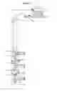
FIG. 1. Schematic view of the artificial lifting system with progressive cavity motor in the background for oil extraction.
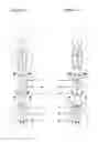
FIG. 2. Schematic detailed view of the progressive cavity motor arrangement and the progressive cavity pump, where both have the same sense of helix, but the progressive cavity motor is installed in reverse to the progressive cavity pump.
FIG. 3. Schematic detailed view of the of the progressive cavity motor arrangement and the progressive cavity pump, where the progressive cavity motor has an opposite direction to the direction of the propeller helix of the progressive cavity pump; besides the progressive cavity motor it is installed in the same direction of the progressive cavity pump.
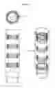
FIG. 4. Front, top and isometric views of axial rowlock (4) with visualization of the circular arrangement of holes (4.1) that allow the passage of fluid from the surface and then activate the progressive cavity motor.
REFERENCES LIST
- 1. STORAGE TANK.
- 2. FLUID INJECTION PUMP.
- 3. TUBING STRING.
- 4. AXIAL ROWLOCK.
- 4.1. CIRCULAR HOLES ARRANGEMENT.
- 5. TAPER BEARING ASSEMBLY.
- 6. A MAJOR AXIS.
- 7. COUPLING SHAFT.
- 8. TUBE.
- 9. FIRST FLEXIBLE SHAFT.
- 10. PROGRESSIVE CAVITY MOTOR.
- 10.1. STATOR OF PROGRESSIVE CAVITY MOTOR.
- 10.2. ROTOR OF PROGRESSIVE CAVITY MOTOR.
- 11. PERFORATED TUBE.
- 12. SECOND FLEXIBLE SHAFT.
- 13. PACKAGING RELEASE.
- 14. PROGRESSIVE CAVITY PUMP.
- 14.1. STATOR OF PROGRESSIVE CAVITY PUMP.
- 14.2. ROTOR OF PROGRESSIVE CAVITY PUMP.
- 15. WELL CASING.
BEST MODE OF THE INVENTION
The current invention delivers an artificial lifting system with a progressive cavity motor in the background to the oil extraction. These motors are driven by injected fluid (water or oil) sent from the surface. As the progressive cavity motor is in the background, the connection between the progressive cavity motor and the progressive cavity pump is a flexible axis with a length less than 6 m. Hence, this implies that reliability of the system increases for the extraction of hydrocarbons. Besides, once the fluid traverse the progressive cavity motor, it returns to the surface, due to communicating vessels effect and a decrease in energy consumption required for the extraction of hydrocarbons is achieved.
MODE OF THE INVENTION
This invention relates to an artificial lifting system that comprises a progressive cavity motor (10) in the background, for the hydrocarbons extraction, which generates a rotational movement, due to the flow of a fluid between a stator (10.1) and a rotor (10.2). This system comprises a storage tank of fluid (1), a pump (2) for injecting fluid, a tubing string (3), that connects the surface with an axial rowlock (4), a tube (8), a stator for a progressive cavity motor (10.1), a perforated tube (11), a stator for a progressive cavity pump (14.1), an annular seal (13), supported between the stator of the progressive cavity pump (14) and the well casing (15), a set of tapered roller bearings (5) supported in the axial rowlock (4), a main shaft (6), supported in the assembly tapered bearing (5), four couplings for shafts (7), two flexible shafts (9 and 12), a rotor (10.2) of the progressive cavity motor and a rotor (14.2) of the progressive cavity pump.
The artificial lifting system with progressive cavity motor (10) in the background, for the extraction of hydrocarbons, consists of a storage tank (1) connected to the fluid suction pump (2) of injection. The discharge of the injection pump is connected to the upper end of the tubing string (3) and this in turn is connected at its lower end to an axial rowlock (4). This axial rowlock has an array of holes in a circular form (4.1), around the seat of the conical bearings. Within the axial bearing a taper bearing assembly (5) that supports the load of the main shaft (6) is installed. This main shaft is connected, via a coupling shaft (7), to one of the flexible shafts (9). At the same time, the other end of the flexible shaft is connected, via a coupling shaft (7), to the motor's rotor (10.2). The motor's rotor is located inside the stator (10.1) of the progressive cavity motor, which is attached to the rowlock (4) through a tube (8). Additionally, the lower end of the rotor (10.2) of the progressive cavity motor is connected, via coupling shafts (7), to the second flexible shaft (12). Likewise, the second flexible shaft is connected at its lower rotor (14.2) to the progressive cavity pump, via coupling shafts (7). The rotor (14.2) of the progressive cavity pump is installed inside the stator (14.1) of the progressive cavity pump, which supports the annular gasket (13). Finally, the lower end of the stator (10.1) of the progressive cavity motor is connected to the upper end of the stator (14.1) of the progressive cavity pump through a perforated tube (11).
The progressive cavity motor (10) comprises a progressive cavity pump with reverse rotation to the progressive cavity pump (14). While the progressive cavity motor receives a fluid to generate a rotational movement, the progressive cavity pump receives rotational motion from the progressive cavity motor to pump the fluid. The progressive cavity motor can be a progressive cavity pump installed opposing the progressive cavity pump, as shown in FIG. 2. The progressive cavity motor can also be a progressive cavity pump with inverse flow of the progressive cavity pump, as shown in FIG. 3.
The system consists of a pump (2) for fluid injection that sucks the fluid that is contained in the storage tank (1) and is discharged through the pipe strings (3) to the axial rowlock (4). Thus, the fluid is directed through the arrangement of the circular holes of the bearing (4.1). Subsequently, the fluid exits the axial rowlock (4) and passes through the annular space between the tube (8) and the first flexible shaft (9) towards the rotor assembly upper mouth (10.2) and stator (10.1), of the progressive cavity motor (10). Once the fluid passes between the rotor and the stator of progressive cavity motor, the rotor begins to rotate. The axial load generated by the rotational movement is transmitted to the flexible shaft (9) and from this to the main shaft (6), that comprises a shoulder (6.1) at the upper end. Thus, the main shaft rotates and is supported on the taper roller bearings (5). Finally, the fluid exits the rotor assembly (10.2) and stator (10.1) of the progressive cavity motor (10) to the lower mouth of the stator towards the outlet holes of the perforated tube (11), returning to surface through communicating vessels.
The rotational movement produced by the passage of fluid in the system is transmitted from the rotor (10.2) of the progressive cavity motor (10) to the rotor (14.2) of the progressive cavity pump (14) via the second flexible shaft (12). When the rotor (14.2) of the progressive cavity pump (14) rotates within the stator (14.1), the oil flows from the lower opening to the upper face of the stator (14.1) of the progressive cavity pump (14), and hence it passes to the outlet holes of the perforated tube (11). When the oil goes out through the perforated tube, it moves to the surface due to the discharge pressure of the progressive cavity pump (14).
INDUSTRIAL APPLICABILITY
In hydrocarbons sector it is known the use of electric or hydraulic heads in the surface as well as a bottom electric motors. Due to the bottom electric motors high speed, the artificial lifting system is only applicable in high-flow or high production wells.
The current invention delivers an artificial lifting system with a progressive cavity motor in the background to the oil extraction. These motors are driven by injected fluid (water or oil) sent from the surface. As the progressive cavity motor is in the background, the connection between the progressive cavity motor and the progressive cavity pump is a flexible axis with a length less than 6 m. Hence, this implies that reliability of the system increases for the extraction of hydrocarbons. Besides, once the fluid traverse the progressive cavity motor, it returns to the surface, due to communicating vessels effect and a decrease in energy consumption required for the extraction of hydrocarbons is achieved.
Claims
1. Artificial lifting system comprising a progressive cavity motor installed in the background for the extraction of hydrocarbons.
2. Artificial lifting system comprising an axial rowlock, which has a circular orifices arrangement, which allows the fluid from the surface into the upper mouth of the progressive cavity motor.
3. Artificial lifting system comprising an axial bearing that supports the axial load, exerted by the rotor of the progressive cavity motor and the rotor of the progressive cavity pump.
4. Artificial lifting system comprising a perforated tube that allows both the fluid motor in the discharge of the progressive cavity motor and the fluid in the progressive discharge of the progressive cavity pump exit the annular space between the motor stator of progressive cavity and the well casing.
5. Artificial lifting system comprising in the surface a pump that takes and injects into a tubing strings and sends it to the space between the rotor and the stator of the progressive cavity motor, to generate a rotational movement in the rotor of progressive cavity motor.
6. Artificial lifting system comprising a ring gasket installed between the stator of the progressing cavity pump and the casing well.
7. Artificial lifting system comprising a progressive cavity motor that corresponds to a progressive cavity pump with a reverse rotation with the progressive cavity pump.
8. Artificial lifting system comprising a progressive cavity motor that can be a progressive cavity pump installed opposing the progressive cavity pump.
9. Artificial lifting system comprising a progressive cavity motor that can be a progressive cavity pump with reverse flow to the progressive cavity pump.
Images & Drawings included:

Sources:
- United States Patent and Trademark Office - verify current appl. status at the USPTO↗
Recent applications in this class:
- » 20240426214 2024-12-26
ROTOR TILT COMPENSATION IN PDM STATORS - » 20240044251 2024-02-08
High modulus liners in PDM stators with diameter reliefs compensating for rotor tilt - » 20230065707 2023-03-02
Positive displacement motor stators with diameter reliefs compensating for rotor tilt - » 20180347361 2018-12-06
Mud motor inverse power section - » 20160084085 2016-03-24
Stator for an eccentric screw pump - » 20150125329 2015-05-07
PROGRESSING CAVITY PUMP/MOTOR - » 20140377112 2014-12-25
Nitrogen- and ceramic-surface-treated components for downhole motors and related methods - » 20120258001 2012-10-11
Progressing cavity pump/motor