Package type compressor
US20160097389A1
2016-04-07
14/869,176
2015-09-29
✅ Patent granted
US 10,895,155 B2
2021-01-19
-
-
Connor J Tremarche
Crowell & Moring LLP
2036-07-16
Abstract:
[Problem] To provide a package type compressor capable of improving the productivity by reducing the restriction in arrangement of respective parts while securing the cooling of an inverter concerning the cooling of the package type compressor which houses a compressor body, a motor driving the compressor body and the inverter controlling rotation of the motor in a package.
[Means for Resolution] A package type compressor includes a compressor body compressing the air, a motor driving the compressor body, an inverter controlling rotation speed of the motor and a cooling fan provided in the compressor body, in which the inverter is provided in an intake path of cooling air generated by the cooling fan provided in the compressor body.
Assignee:
- Hitachi Industrial Equipment Systems Co., Ltd. 451 🇯🇵 Tokyo, Japan
Applicant:
Interested in similar patents?
Get notified when new applications in this technology area are published.
Classification:
F04B39/066 » CPC further
Component parts, details, or accessories, of pumps or pumping systems specially adapted for elastic fluids, not otherwise provided for in, or of interest apart from, groups -; Cooling; Heating; Prevention of freezing Cooling by ventilation
F01C21/007 » CPC main
Component parts, details or accessories not provided for in groups - General arrangements of parts; Frames and supporting elements
F04B53/08 » CPC further
Component parts, details or accessories not provided for in, or of interest apart from, groups - or - Cooling; Heating; Preventing freezing
F04C29/04 » CPC further
Component parts, details or accessories of pumps or pumping installations, not provided for in groups - Heating; Cooling ; Heat insulation
F04C18/0215 » CPC main
Rotary-piston pumps specially adapted for elastic fluids of arcuate-engagement type, i.e. with circular translatory movement of co-operating members, each member having the same number of teeth or tooth-equivalents both members having co-operating elements in spiral form where only one member is moving
F04C2240/403 » CPC further
Components; Electric motor with inverter for speed control
F04C18/02 IPC
Rotary-piston pumps specially adapted for elastic fluids of arcuate-engagement type, i.e. with circular translatory movement of co-operating members, each member having the same number of teeth or tooth-equivalents
F04C23/02 » CPC further
Combinations of two or more pumps, each being of rotary-piston or oscillating-piston type, specially adapted for elastic fluids; Pumping installations specially adapted for elastic fluids; Multi-stage pumps specially adapted for elastic fluids Pumps characterised by combination with or adaptation to specific driving engines or motors
F01C21/00 IPC
Component parts, details or accessories not provided for in groups -
F04B39/06 IPC
Component parts, details, or accessories, of pumps or pumping systems specially adapted for elastic fluids, not otherwise provided for in, or of interest apart from, groups - Cooling; Heating; Prevention of freezing
Description
TECHNICAL FIELD
The present invention relates to a compressor which compresses the fluid such as air and refrigerant, and particularly relates to the cooling of a package type compressor which houses a compressor body, a motor driving the compressor body and an inverter controlling the rotation of the motor in the package.
BACKGROUND ART
As a background art of the present technique, there is JP-A-2008-175156 (Patent Literature 1). In Patent Literature 1, there is disclosed a compressor including a compression part, a motor driving the compression part, an inverter device driving the motor, a cooling fan exhausting air used for cooling the interior of the compressor inside a package, in which an air suction port is provided in the package, and air taken in from the air suction port cools the inverter device, then, cools the motor.
CITATION LIST
Patent Literature
[PTL 1] JP-A-2008-175156
SUMMARY OF INVENTION
Technical Problem
As the compressor disclosed in Patent Literature 1 is provided with the cooling fan for cooling the interior of the package, a motor dedicated to the cooling fan is necessary, therefore, there are problems that costs are increased and that the arrangement of respective parts is restricted, and the productivity is decreased.
The invention has been made in view of the above problems in related art, and an object thereof is to provide a package type compressor capable of improving the productivity by reducing the restriction in arrangement of respective parts while securing the cooling of the inverter.
Solution of Problem
The invention applies structures, for example, descried in claims for solving the above problems. The invention includes plural means for solving the above problems. As one of the means, there is provided a package type compressor including a compressor body compressing the air, a motor driving the compressor body, an inverter controlling rotation speed of the motor, and a cooling fan provided in the compressor body, in which the inverter is provided in an intake path of cooling air generated by the cooling fan provided in the compressor body.
Advantageous Effects of Invention
According to the invention, it is possible to provide a package type compressor capable of improving the productivity by reducing the restriction in arrangement of respective parts while securing the cooling of the inverter.
BRIEF DESCRIPTION OF DRAWINGS
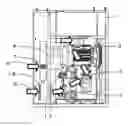
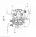
FIG. 1 is a schematic view showing a state where part of outer panels is removed in a package type compressor according to Example 1.
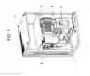
FIG. 2 is a schematic view showing the flow of cooling air of the package type compressor according to Example 1.
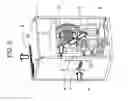
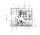
FIG. 3 is a schematic view showing the flow of cooling air in a back side of the package type compressor according to Example 1.
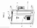
FIG. 4 is a schematic view showing the flow of cooling air in a compressor body according to Example 1.
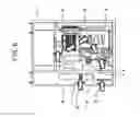
FIG. 5 is a schematic view showing a state where part of outer panels is removed in a package type compressor according to Example 2.
FIG. 6 is a schematic view showing a state where part of outer panels is removed in a package type compressor according to Example 3.
DESCRIPTION OF EMBODIMENTS
Hereinafter, examples of the invention will be explained with reference to the drawings.
Example 1
FIG. 1 is a schematic view showing a state where part of outer panels is removed in a package type compressor according to the example. In FIG. 1, a scroll compressor body 2 compressing the air, a motor 3 driving the scroll compressor body 2, an inverter 4 controlling rotation speed of the motor 3 and a cooling fan 5 cooling the scroll compressor body 2 are installed inside a casing 1. The inverter 4 is installed in an intake path of cooling air in the scroll compressor body 2. The cooling fan 5 is built in the scroll compressor body 2, which rotates in synchronization with the rotation of the compressor body to perform cooling.
Though the example in which the scroll compressor is used as the compressor body is explained, the compressor body is not limited to this. Compressor bodies other than the scroll compressor body requiring cooling by the cooling air may be used, for example, a reciprocating compressor, a screw compressor and so on may be used.
The flow of cooling air according to the example will be explained with reference to FIG. 2. FIG. 2 is a schematic view showing the flow of cooling air of the package type compressor according to the example, showing a state where a side surface part in FIG. 1 is covered by a panel. In FIG. 2, a cooling air 6 shown by arrows is first sucked by the cooling fan 5 through an intake port 7 provided on the panel from the outside of the casing 1 and passes a circulation path including a duct surrounding the inverter 4 as shown in FIG. 1, thereby cooling the inverter 4. It is also preferable that the inverter is provided with a radiating fin to be cooled in the path of cooling air. After that, the motor 3 and the scroll compressor body 2 are cooled by the cooling air. The cooling air used for cooling the scroll compressor body 2 is exhausted from an exhaust port 8 through a back side in FIG. 2 as shown by dotted-line arrows.
The flow of cooling air in the back side of the package type compressor according to the example will be explained with reference to FIG. 3. FIG. 3 is a view of the package type compressor of FIG. 2 seen from the back, which is a schematic view in a state where part of the otter panels is removed. In FIG. 3, an after cooler 9 which cools the air compressed by the scroll compressor body and an air tank 10 storing the compressed air cooled by the after cooler 9 are arranged in the back of the package type compressor. The cooling air 6 cools the after cooler 9 after cooling the scroll compressor body 2, then, exhausted from the exhaust port 8.
FIG. 4 is a schematic view showing the flow of cooling air in the scroll compressor body 2 according to the example, which is a cross sectional view of the scroll compressor body 2 seen from above. Concerning the cooling air 6, the cooling air is sucked as shown by an arrow 6-1 by the cooling fan 5 of the scroll compressor body 2, and the scroll compressor body 2 is cooled by cooling air shown by an arrow 6-3 via a duct 11 as shown by an arrow 6-2, then, the cooling air is exhausted as shown by an arrow 6-4 to be circulated to the after cooler 9 side in the back side of the package type compressor.
As described above, the inverter 4 is installed in the intake path of cooling air by the cooling fan 5 provided in the scroll compressor body 2 and is cooled by the cooling air 6 generated by the cooling fan 5 which cools the scroll compressor body 2, therefore, it is not necessary to provide a cooling fan dedicated to the inerter 4. Accordingly, the costs can be reduced and the productivity can be improved by reducing the restriction in arrangement of respective parts while securing the cooling of the inverter. Also in the example, the motor 3 can be cooled by providing the motor 3 in the path of cooling air.
In the case where the cooling fan dedicated to the inverter 4 or, a dedicated cooling far for cooling the entire package type compressor is provided separately from the cooling fan provided in the compressor body for cooling the compressor body, it is difficult to use the package type compressor when the dedicated cooling fan is broken. Whereas, in the example, the cooling fan is normal when the compressor body is normal, therefore, the package type compressor can be used, which leads to an advantage that the reliability is increased. Additionally, as the cooling fan which cools the compressor body operates in synchronization with the motor which drives the compressor body, the rotation of the compressor body is decreased. When the rotation of the compressor body is reduced and the compressing operation of the compressor is decreased, the temperature increase is reduced and necessity of cooling is also reduced, therefore, there is another advantage that an energy-saving effect can be expected as it is not necessary to operate the cooling fan when not required.
Example 2
The example is one in which a pipe connecting an air tank for storing compressed air to an air dryer for dehumidifying the compressed air is provided in the path of cooling air.
FIG. 5 is a schematic view showing a state where part of outer panels is removed in a package type compressor according to the example. The same numerals are given to the same components as those of Example 1, and explanation thereof is omitted.
In FIG. 5, a pipe 13 connecting an air tank 10 for storing compressed air compressed by the scroll compressor body to an air dryer 12 for dehumidifying the compressed air is a flow path of the compressed air, therefore, the pipe 13 is provided in the path of the cooling air 6. Accordingly, the compressed air flowing into the air dryer 12 can be cooled without providing a dedicated cooling fan for cooling the compressed air, thereby reducing the costs and improving the productivity by reducing the restriction in arrangement of respective parts while improving the reliability of the air dryer 12.
Though the pipe 13 connecting the air tank 10 to the air dryer 12 is provided in the path. of the cooling air 6 in the example, for example, the path of the compressed air which connects the compressor body to the air tank may be cooled. As the compressed air discharged from the compressor body follows the path to the air tank via the after cooler in the example, for example, the a pipe 14 which is a path of compressed air which connects the compressor body to the after cooler may be cooled and a pipe 15 which is a path of compressed air which connects the after cooler to the air tank may be cooled.
The air tank 10 and the air dryer 12 can be installed outside the casing 1. In this case, the path of compressed. air cooled by the cooling air 6 is the above path of compressed air which connects the scroll compressor body 2 to the outlet of the compressed air in the casing 1.
Example 3
The example is one in which a second intake port allowing the cooling air to flow into the cooling fan without passing the cooling path to the inverter.
FIG. 6 is a schematic view showing a state where part of outer panels is removed in a package type compressor according to the example. The same numerals are given to the same components as those of Example 1, and explanation thereof is omitted.
In FIG. 6, an intake port 16 allowing the cooling air to flow into the cooling fan 5 without passing the cooling path to the inverter 4 is provided on the panel separately from the intake port 7 for cooling the inverter 4. Accordingly, part of the cooling air for cooling the scroll compressor body 2 can be directly taken in from the outside of the casing, therefore, the cooling efficiency of the scroll compressor body 2 can be increased and the reliability can be improved as compared with Example 1 in which all the cooling air passes the invert. Moreover, as the air taken in from air suction ports 17 of the scroll compressor body 2, not air the temperature of which is increased inside the package type compressor but outside air taken in from the intake port 16 can be directly taken in, which is effective to reduce the temperature of the scroll compressor body 2.
Though the example has been explained based on Example 1, the present example may be applied in Example 2.
The examples have been explained as the above, and the present invention is not limited to the above examples and various modification examples are included. For example, the above examples have been explained in detail for explaining the present invention so as to be easy to understand, and the present invention is not always limited to examples which include all the components explained above. It is also possible to replace part of components in one example with components of another example as well as to add components of another example to components of one example. Furthermore, addition, omission and replacement can be performed with respect to part of components of respective examples.
REFERENCE SIGNS LIST
1: casing, 2: scroll compressor body, 3: motor, 4: inverter, 5: cooling fan, 6, 6-1, 6-2, 6-3 and 6-4: cooling air, 7, 16: intake port, 8: exhaust port, 9: after cooler, 10: air tank, 11: duct, 12: air dryer, 13, 14, 15: pipe, 17: air suction port of compressor body
Claims
1. A package type compressor comprising:
a compressor body compressing the air;
a motor driving the compressor body;
an inverter controlling rotation speed of the motor; and
a cooling fan provided in the compressor body,
wherein the inverter is provided in an intake path of cooling air generated by the cooling fan provided in the compressor body.
2. The package type compressor according to claim 1,
wherein, the cooling fan is built in the compressor body and rotates in synchronization with the rotation of the compressor body.
3. The package type compressor according to claim 1,
wherein the motor is provided in the path of the cooling air between the inverter and the compressor body.
4. The package type compressor according to claim 1, further comprising:
an after cooler cooling compressed air compressed by the compressor body,
wherein the after cooler is provided in the path of the cooling air.
5. The package type compressor according to claim 1,
wherein a path of the compressed air compressed by the compressor body is provided in the path of the cooling air.
6. The package type compressor according to claim 5,
wherein the path of the compressed air is a pipe Connecting the compressor body to the after cooler.
6. The package type compressor according to claim 5,
wherein the path of the compressed air is a pipe connecting the after cooler connected to the compressor body to an air tank.
8. The package type compressor according to claim 5,
wherein the path of the compressed air is a pipe connecting the air tank storing the compressed air to an air dryer.
9. The package type compressor according to claim 1,
wherein plural intake ports of the cooling air are provided.
10. The package type compressor according to claim 9,
wherein the plural intake ports of the cooling air include as intake port of cooling air for cooling the inverter and an intake port of cooling air for cooling the compressor body.
11. The package type compressor according to claim 1,
wherein the compressor body is a scroll compressor.
Images & Drawings included:
Sources:
- United States Patent and Trademark Office - verify current appl. status at the USPTO↗
Similar patent applications:
- » 20200300246
Package-type compressor - » 20210102540
Package-type compressor - » 20230332603
PACKAGE-TYPE COMPRESSOR - » 20180187684
Package-type air-cooled screw compressor having a cooling air exhaust opening in the package with a duct extended downward with a lower-end inlet placed not viewable from the center position of the compressor
Recent applications in this class:
- » 20250283467 2025-09-11
SCROLL MACHINE AND REFRIGERATION SYSTEM - » 20250283466 2025-09-11
SCROLL COMPRESSOR AND AIR CONDITIONING DEVICE - » 20250270995 2025-08-28
ELECTRIC COMPRESSOR WITH PASSIVE PRESSURE SYSTEM BETWEEN HIGH AND LOW PRESSURE REGIONS - » 20250264102 2025-08-21
SCROLL COMPRESSOR WITH ROLLING ELEMENT BEARINGS - » 20250243861 2025-07-31
SCROLL COMPRESSOR HAVING OVERHEATING PREVENTION DEVICE - » 20250243860 2025-07-31
SCROLL COMPRESSOR - » 20250223964 2025-07-10
SCROLL COMPRESSOR - » 20250207587 2025-06-26
SCROLL PUMP - » 20250188928 2025-06-12
CRANKSHAFT ASSEMBLY FOR SCROLL DEVICES - » 20250188927 2025-06-12
Heat Pump Systems With Capacity Modulation
Recent applications for this Assignee:
- » 20250188921 2025-06-12
COMPRESSOR - » 20250179387 2025-06-05
SLIDING MATERIAL AND GAS COMPRESSOR - » 20250075698 2025-03-06
Screw compressor - » 20250042580 2025-02-06
UNMANNED AERIAL VEHICLE SUPPORT DEVICE AND UNMANNED AERIAL VEHICLE SUPPORT SYSTEM - » 20250035115 2025-01-30
SCREW COMPRESSOR - » 20240375033 2024-11-14
SAFETY WORK DEVICE - » 20240301882 2024-09-12
COMPRESSOR - » 20240280114 2024-08-22
LIQUID-FEED-TYPE GAS COMPRESSOR - » 20240189809 2024-06-13
SAFETY CABINET - » 20240143958 2024-05-02
Code Generation System and Code Generation Method