Drive train for hoisting gear
US20160101969A1
2016-04-14
14/892,705
2014-02-12
✅ Patent granted
US 10,759,638 B2
2020-09-01
WO; PCT/EP2014/052693; 20140212
WO; WO2014/187578; 20141127
Sang K Kim | Nathaniel L Adams
Panitch Schwarze Belisario & Nadel LLP
2035-03-23
Abstract:
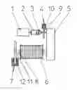
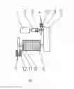
A drive train is provided for hoisting gears, and in particular for hazardous transports. The drive train includes a drive motor (1), a cable drum (6) connected thereto, a reduction transmission (5) arranged between the drive motor (1) and the cable drum (6), a service brake (4) provided between the drive motor (1) and the reduction transmission (5) and a safety brake (7). To prevent damage to the reduction transmission (5) in the event of an emergency stop braking an automatic overrun disconnect means can be provided between the drive motor (1) and the service brake (4). The overrun disconnect means is preferably in the form of a freewheel (2).
Inventors:
- Christof LAUTWEIN 3 🇩🇪 Friesenhagen, Germany
- Christian SPURA 2 🇩🇪 Castrop-Rauxel, Germany
- Christoph WAGENER 3 🇩🇪 Geldern, Germany
Assignee:
- M.A.T MALMEDIE ANTRIEBSTECHNIK GMBH 4 🇩🇪 SOLINGEN, Germany
Applicant:
Interested in similar patents?
Get notified when new applications in this technology area are published.
Classification:
B66D1/16 » CPC main
Rope, cable, or chain winding mechanisms; Capstans; Driving gear; Power transmissions between power sources and drums or barrels the drums or barrels being freely rotatable, e.g. having a clutch activated independently of a brake
B66D1/58 » CPC further
Rope, cable, or chain winding mechanisms; Capstans; Safety gear responsive to excess of load
B66D1/14 » CPC further
Rope, cable, or chain winding mechanisms; Capstans; Driving gear Power transmissions between power sources and drums or barrels
B66D1/12 » CPC further
Rope, cable, or chain winding mechanisms; Capstans; Driving gear incorporating electric motors
B66D1/54 » CPC further
Rope, cable, or chain winding mechanisms; Capstans Safety gear
B66D5/00 » CPC further
Braking or detent devices characterised by application to lifting or hoisting gear, e.g. for controlling the lowering of loads
Description
CROSS-REFERENCE TO RELATED APPLICATIONS
This application is a Section 371 of International Application No. PCT/EP2014/052693, filed Feb. 12, 2014 which was published in the German language on Nov. 27, 2014 under International Publication No. WO 2014/187578 A1 and the disclosure of which is incorporated herein by reference.
BACKGROUND OF THE INVENTION
The invention concerns a drive train for hoisting gears, in particular for hazardous transports, comprising a drive motor, a cable drum connected thereto, a reduction transmission arranged between the drive motor and the cable drum, a service brake provided between the drive motor and the reduction transmission and a safety brake.
If hoisting gears are provided for the transport of hazardous items, for example molten materials or also radioactive materials, a safety brake is generally also provided in the drive train, besides the service brake. The safety brake which serves for emergency stop braking is normally carried on the shaft of the cable drum.
In an emergency stop braking situation in a “lower” load situation there is a reversal in the load direction and thus a torque shock occurs in the transmission, as a consequence of different application times for the safety brake and the service brake. That torque shock leads to an overload as well as stressing in the transmission. That overload and transmission stressing which occur upon emergency stop braking result in particular from the rotating inertial masses of the motor and the
BRIEF SUMMARY OF THE INVENTION
Therefore the object of the invention is to avoid the torque shock linked to the reversal in the load direction and the stresses caused thereby in the transmission.
According to an embodiment of the invention that object is attained in that, provided between the drive motor and the service brake is an automatic overrun disconnect means.
These features according to an embodiment of the invention provide that the rotating masses of the motor are separated from the drive train. Damage in the drive train and in particular in
In the embodiment illustrated in FIG. 1, both the service brake 4 and also the safety brake 7 are designed in the manner of a disk brake.
The freewheel 2 arranged between the drive motor 1 and the coupling 3 is desirably in the form of a noiselessly operating clamping roller freewheel.
The coupling 3 arranged in FIG. 1 between the freewheel 2 and the service brake 4 is in the form of a rigid coupling.
Alternatively the coupling 3 can also be in the form of an electrically switchable releasable coupling to separate the drive motor 1 from the reduction transmission 5. For that specified case it would be possible to dispense with a freewheel 2.
If an emergency stop is triggered when lowering the suspended load the service brake 4 and the safety brake 7 are closed. By virtue of the usual brake dimensioning the safety brake 7 which serves as the emergency off stopping brake requires a shorter application time than the service brake 4. As a result the rotary movement of the cable drum 6 is stopped before the rotary movement of the input shaft of the reduction transmission has come to a halt. Thus, without the measures according to the invention, a shock torque would occur, which acts in the opposite direction to the actual load direction.
That torque transmitted by the inertia mass of the drive motor 1, in conventional drive trains, causes a shock-like reversal in direction of the torque in the transmission. The time process of the reversal in direction of the torque takes place during the difference in application times between the safety brake 7 and the service brake 4.
Then, in the conventional drive trains, the inertia mass in opposite relationship to the load direction produces in the reduction transmission 5 a change in tooth flank from the load flank to the opposite flank (rearward load flank). As a result of that, a shock loading occurs at the opposite flank, which in the conventional drive trains would lead to considerable damage to the transmission. That transmission damage can range from slight surface damage to the tooth flank to tooth breakage and thus failure of the transmission.
Such damage is very effectively prevented by the arrangement of an automatic overrun disconnect means or the freewheel 2 in the drive train according to the invention. It is already the case that upon response of the safety brake 7 which has a very short application time the freewheel 2 takes effect immediately upon stoppage of the reduction transmission 5, that is to say the torque of the inertial rotating masses of the drive motor, due to the response of the freewheel 2, is no longer transmitted to the reduction transmission 5 which is connected directly to the cable drum 6. The action of the freewheel 2 takes place immediately with actuation of the safety brake 7, and more specifically still before the service brake 4 provided with a lesser application time comes into engagement.
Consequently only one torque direction is predetermined by the arrangement of the freewheel 2 in the drive train according to the invention so that, in the event of emergency stop braking, no damage to the reduction transmission can occur. The features according to the invention can thus effectively protect a corresponding drive train for hoisting gears from damage so that the service life thereof is increased.
It will be appreciated by those skilled in the art that changes could be made to the embodiments described above without departing from the broad inventive concept thereof. It is understood, therefore, that this invention is not limited to the particular embodiments disclosed, but it is intended to cover modifications within the spirit and scope of the present invention as defined by the appended claims.
Claims
1. A drive train for hoisting gears comprising:
a drive motor (1),
a cable drum (6) connected thereto,
a reduction transmission (5) arranged between the drive motor (1) and the cable drum (6),
a service brake (4) provided between the drive motor (1) and the reduction transmission (5)
a safety brake (7), and
an automatic overrun disconnected means positioned between the drive motor (1) and the service brake (4).
2. The drive train of claim 1, wherein the overrun disconnect means is an overrun coupling.
3. The drive train of claim 2, wherein the overrun coupling is a freewheel (2).
4. The drive train of claim 3, wherein the freewheel (2) is a clamping roller freewheel.
5. The drive train of claim 1, wherein the overrun disconnect means is a releasable coupling.
6. The drive train of claim 5, wherein the releasable coupling is electrically switchable.
Images & Drawings included:
Sources:
- United States Patent and Trademark Office - verify current appl. status at the USPTO↗
Recent applications in this class:
- » 20240124278 2024-04-18
WINCH WITH ADVANCED ELECTRICAL AND MECHANICAL SMART CONTROLS - » 20190194002 2019-06-27
Remote winch clutch system - » 20180118529 2018-05-03
Winch including rotatable tie structure - » 20160176687 2016-06-23
Remote winch clutch system - » 20150368076 2015-12-24
Coupling device - » 20140326569 2014-11-06
Resetting device - » 20140252286 2014-09-11
Remote winch clutch system - » 20140217341 2014-08-07
Marine vessel winch equipped with hermetically sealed clutch - » 20100258773 2010-10-14
Drum winch - » 20100102287 2010-04-29
Lifting gear
Recent applications for this Assignee:
- » 20170305729 2017-10-26
System arrangement of lifting mechanisms and method of operating the system arrangement - » 20160280515 2016-09-29
Overload protection device for cable strands - » 20080140289 2008-06-12
System arrangement of a lifting device, in particular for a container crane for the lifting of loads and moving for the operation of the system arrangement