Air spring piston with integrated sealing
US20160102727A1
2016-04-14
14/880,730
2015-10-12
✅ Patent granted
US 9,895,777 B2
2018-02-20
-
-
Melanie Torres Williams
2035-10-12
Abstract:
An air spring for air suspension system comprises a piston assembly and a damper assembly where the piston assembly is spaced apart from the damper assembly to at least partially define an air chamber. A seal is molded with piston walls to form an integrated piston assembly. The seal includes at least one sealing lip extending radially inward from the piston assembly at an angle that is non-perpendicular to an axis of the damper and the at least one sealing lip contacts the damper assembly when the piston assembly and the damper assembly are assembled together to seal the air chamber.
Inventors:
- Ralf Pielock 6 🇩🇪 Essel, Germany
- Christian Schallmeier 9 🇺🇸 Lake Orion, MI, United States
- Garrett Mark Pniewski 13 🇺🇸 Bloomfield Hills, MI, United States
- Sunny Makkar 10 🇺🇸 Troy, MI, United States
Assignee:
- CONTINENTAL AUTOMOTIVE SYSTEMS, INC. 998 🇺🇸 Auburn Hills, MI, United States
Applicant:
Interested in similar patents?
Get notified when new applications in this technology area are published.
Classification:
F16F9/3214 » CPC main
Springs, vibration-dampers, shock-absorbers, or similarly-constructed movement-dampers using a fluid or the equivalent as damping medium; Details; Constructional features of pistons
F16F9/368 » CPC further
Springs, vibration-dampers, shock-absorbers, or similarly-constructed movement-dampers using a fluid or the equivalent as damping medium; Details; Special sealings, including sealings or guides for piston-rods Sealings in pistons
F16F2226/04 » CPC further
Manufacturing; Treatments Assembly or fixing methods; methods to form or fashion parts
F16F2230/30 » CPC further
Purpose; Design features Sealing arrangements
F16F9/32 IPC
Springs, vibration-dampers, shock-absorbers, or similarly-constructed movement-dampers using a fluid or the equivalent as damping medium Details
F16F9/057 » CPC further
Springs, vibration-dampers, shock-absorbers, or similarly-constructed movement-dampers using a fluid or the equivalent as damping medium using gas only or vacuum in a chamber with a flexible wall the flexible wall being of the rolling diaphragm type characterised by the piston
F16F9/369 » CPC further
Springs, vibration-dampers, shock-absorbers, or similarly-constructed movement-dampers using a fluid or the equivalent as damping medium; Details; Special sealings, including sealings or guides for piston-rods Sealings for elements other than pistons or piston rods, e.g. valves
B60G11/27 » CPC further
Resilient suspensions characterised by arrangement, location or kind of springs having fluid springs only, e.g. hydropneumatic springs wherein the fluid is a gas
B60G15/14 » CPC further
Resilient suspensions characterised by arrangement, location or type of combined spring and vibration damper, e.g. telescopic type having fluid spring and fluid damper the damper being connected to the stub axle and the spring being arranged around the damper
F16F9/084 » CPC further
Springs, vibration-dampers, shock-absorbers, or similarly-constructed movement-dampers using a fluid or the equivalent as damping medium using both gas and liquid in a chamber with a flexible wall comprising a gas spring contained within a flexible wall, the wall not being in contact with the damping fluid, i.e. mounted externally on the damper cylinder
F16F9/36 IPC
Springs, vibration-dampers, shock-absorbers, or similarly-constructed movement-dampers using a fluid or the equivalent as damping medium; Details Special sealings, including sealings or guides for piston-rods
B60G2202/152 » CPC further
Indexing codes relating to the type of spring, damper or actuator; Type of spring; Fluid spring Pneumatic spring
B60G2204/1262 » CPC further
Indexing codes related to suspensions or to auxiliary parts; Mounting of suspension elements; Mounting of springs or dampers; Mounting of pneumatic springs on a damper
B60G2204/45021 » CPC further
Indexing codes related to suspensions or to auxiliary parts; Auxiliary suspension parts; Adjustment of suspensions; Stops limiting travel using resilient buffer for limiting upper mount movement of a McPherson strut
B60G2206/82 » CPC further
Indexing codes related to the manufacturing of suspensions: constructional features, the materials used, procedures or tools; Constructional features of suspension elements, e.g. arms, dampers, springs; Manufacturing procedures Joining
B23P15/10 » CPC main
Making specific metal objects by operations not covered by a single other subclass or a group in this subclass pistons
F16F9/05 IPC
Springs, vibration-dampers, shock-absorbers, or similarly-constructed movement-dampers using a fluid or the equivalent as damping medium using gas only or vacuum in a chamber with a flexible wall the flexible wall being of the rolling diaphragm type
Description
CROSS REFERENCE TO RELATED APPLICATION
This application claims priority to U.S. Provisional Application No. 62/063,116 filed on Oct. 13, 2014.
TECHNICAL FIELD
The present disclosure relates to automotive vehicles and more particularly to suspension systems for automotive vehicles.
BACKGROUND
Suspension systems for automotive vehicles provide vehicle passengers with a more comfortable ride. Air suspension systems utilize air springs, rather than traditional coil springs. Air suspension systems provide different suspension qualities that may be preferable in some vehicles to traditional coil spring suspensions.
A conventional air spring is a device that is arranged between a vehicle body and chassis. The typical air spring has at least one working space that is filled with compressed air. Air spring pistons typically seal the air chamber against a hydraulic shock absorber (damper). This can be done in multiple ways. One common way is through use of an O ring.
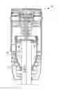
In FIG. 1 a portion of a prior art air spring assembly 10 for a motor vehicle is shown. The air spring 10 has a centrally arranged shock absorber (damper) 14. A piston 12 surrounds the shock absorber 14 and is connected via the air spring cover (not shown) to the vehicle body. The shock absorber 14 is connected, via a connecting flange (not shown) to a wheel support of the chassis in the conventional manner.
The piston 12 and the shock absorber 14 are spaced apart to define an air chamber 16 therebetween. At one end an O-ring 22 seals the air chamber 16 from any air leakages. A c-ring 18 and a support ring 20 are located at one end of the shock absorber 14, between the shock absorber 14 and the piston 12 to support and secure the o-ring seal 22 in place. A groove 23 on the shock absorber 14 holds the c-ring 18 and support ring 20 to prevent axial movement along the shock absorber 14.
The background description provided herein is for the purpose of generally presenting the context of the disclosure. Work of the presently named inventors, to the extent it is described in this background section, as well as aspects of the description that may not otherwise qualify as prior art at the time of filing, are neither expressly nor impliedly admitted as prior art against the present disclosure.
SUMMARY
An air spring for air suspension system comprises a piston assembly and a damper assembly where the piston assembly is spaced apart from the damper assembly to at least partially define an air chamber. A seal is molded with piston walls to form an integrated piston assembly. The seal includes at least one sealing lip extending radially inward from the piston assembly at an angle that is non-perpendicular to an axis of the damper and the at least one sealing lip contacts the damper assembly when the piston assembly and the damper assembly are assembled together to seal the air chamber.
A method of manufacturing a piston assembly, comprises forming a seal using an injection mold form and forming piston walls at least partially surrounding the seal with the injection molding form to create an integrated piston assembly. The piston is assembled to surround a damper assembly, such that an air chamber is at least partially defined by the piston assembly and the damper assembly. A sealing lip extends from the seal and is in contact with the damper assembly to seal the air chamber.
Further areas of applicability of the present disclosure will become apparent from the detailed description provided hereinafter. It should be understood that the detailed description and specific examples, while indicating the preferred embodiment of the disclosure, are intended for purposes of illustration only and are not intended to limit the scope of the disclosure.
BRIEF DESCRIPTION OF THE DRAWINGS
The present disclosure will become more fully understood from the detailed description and the accompanying drawings, wherein:
FIG. 1 is a schematic illustration of an air spring assembly of the prior art;
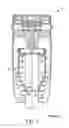
FIG. 2 is a schematic illustration of an air spring assembly of the present invention;
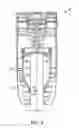
FIG. 3 is an enlarged schematic illustration of a cross-section of the piston and seal for the air spring assembly of FIG. 2; and
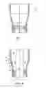
FIG. 4 is an enlarged schematic illustration of a cross-section of the piston, seal and damper for the air spring assembly of FIGS. 2-3.
DETAILED DESCRIPTION
The following description is merely exemplary in nature and is in no way intended to limit the disclosure, its application, or uses. For purposes of clarity, the same reference numbers will be used in the drawings to identify similar elements. Referring to FIGS. 2-4, an air spring assembly 10′ for a motor vehicle is shown. The air spring 10′ has a centrally arranged shock absorber (damper) 14′. A piston 12′ surrounds the shock absorber 14′ and is connected via the air spring cover (not shown) to the vehicle body. The shock absorber 14′ is connected, via a connecting flange (not shown) to a wheel support of the chassis in the conventional manner.
The piston 12′ and the shock absorber 14′ are spaced apart to define an air chamber 16 therebetween. The piston assembly 12′ of the present invention is made of plastic material molded with an integrated elastomeric seal 24. The seal 24 seals the air chamber 16 from any air leakages.
The sealing lip 26 extends radially inward from the piston 12′. The sealing lip 26 is formed to extend at a non-perpendicular angle. Therefore, when the piston 12′ and the damper 14′ are assembled together the sealing lip 26 extends upward toward the top of the piston 12′ and damper 14′.
During operation of the vehicle, pressure within the air chamber 16 pushes downwardly and radially inward on the sealing lip 26, illustrated by arrow 28. In this manner, the sealing effect provided by the seal 24 increases as the pressure within the air chamber 16 increases and pushes the sealing lip 26 more securely against the damper 14′. Therefore, the seal 24 prevents any air leakages from the air chamber 16.
Additionally, the seal 24 shown has one sealing lip 26. However, multiple sealing lips 24 may be used to ensure proper sealing between the piston 12′ and damper 14′. One skilled in the art would be able to determine the preferred number, size and angle of the sealing lip(s) 26 for a particular air spring assembly 10′.
The piston 12′ is formed by plastic injection molding the seal 24 and the piston walls 13 to be an integrated component. The piston 12′ is formed using a two-step injection molding process, where the seal is molded in the first step and then the piston walls 13 are molded in a second step creating the integrated piston 12′. Alternatively, the integrated piston 12′ can be achieved by overmolding the piston walls 13 around the seal 24, which is previously molded through a separate process. The seal 24 is formed from an elastomeric material and the piston walls 13 are formed from plastic material. The piston walls 13 adhere at least partially around the seal 24 to created an integrated component. A seal seat 25 can be shaped into the piston walls 13 during the molding process to help provide support for the seal 24 during operation of the air spring 10′. The seal seat 25 may extend inwardly toward the center of the piston 12′. However, once assembled some clearance between the seal seat 25 and the damper assembly 14 would be present, such that the contact between the damper 14′ and the piston 12′ is by way of the sealing lip 26.
While the best modes for carrying out the invention have been described in detail the true scope of the disclosure should not be so limited, since those familiar with the art to which this invention relates will recognize various alternative designs and embodiments for practicing the invention within the scope of the appended claims.
Claims
What is claimed is:1. An air spring for air suspension system comprising:
a piston assembly and a damper assembly wherein the piston assembly is spaced apart from the damper assembly to at least partially define an air chamber;
a seal molded with piston walls to form an integrated piston assembly, wherein the seal includes at least one sealing lip extending radially inward from the piston assembly at an angle that is non-perpendicular to an axis of the damper; and
wherein the at least one sealing lip contacts the damper assembly when the piston assembly and the damper assembly are assembled together to seal the air chamber.
2. The air spring of claim 1, wherein the air within the air chamber forces the sealing lip further against the damper assembly.
3. The air spring of claim 1, wherein the seal and the piston walls are injection molded in a two-step process to form the integrated piston assembly.
4. The air spring of claim 1, wherein the piston walls are injection molded around the seal to form the integrated piston assembly.
5. A method of manufacturing a piston assembly, comprising:
forming a seal using an injection mold form;
forming piston walls at least partially surrounding the seal with the injection molding form to create an integrated piston assembly;
assembling the piston around a damper assembly, such that an air chamber is at least partially defined by the piston assembly and the damper assembly; and
wherein a sealing lip extending from the seal is in contact with the damper assembly to seal the air chamber.
6. The method of claim 5, further comprising increasing the force on the sealing lip toward the damper assembly with the air in the air chamber.
Images & Drawings included:
Sources:
- United States Patent and Trademark Office - verify current appl. status at the USPTO↗
Recent applications in this class:
- » 20250163985 2025-05-22
PISTON PILOT VALVE ASSEMBLY AND FREQUENCY SENSITIVE SHOCK ABSORBER HAVING SAME - » 20240426362 2024-12-26
FLOATING PISTON FOR SINGLE-TUBE SHOCK ABSORBER - » 20240410441 2024-12-12
DAMPING FORCE GENERATION DEVICE - » 20240410440 2024-12-12
PISTON FLUID FLOW DYNAMICS, TEMPERATURE STABILITY, AND NOISE MITIGATION - » 20240068541 2024-02-29
DAMPER ASSEMBLY AND HYDRAULIC SHOCK ABSORBER COMPRISING THE SAME - » 20230144321 2023-05-11
Piston assembly formed of interlocking piston members - » 20230103233 2023-03-30
DILATANT FLUID BASED OBJECT MOVEMENT CONTROL MECHANISM - » 20230035676 2023-02-02
Hydraulic shock absorber - » 20220403905 2022-12-22
Device for stabilizing movements of two parts of a body region and/or of a sports device - » 20220307566 2022-09-29
DAMPER ASSEMBLY
Recent applications for this Assignee:
- » 20250168811 2025-05-22
TRANSCEIVER ASSIGNMENT AND POSITION INITIALIZATION SYSTEM AND METHOD - » 20250100488 2025-03-27
BATTERY MANAGEMENT FOR C-V2X (CELLULAR VEHICLE-TO-EVERYTHING) - » 20250050850 2025-02-13
DRIVER DIRECTIONAL CONTROL DURING BRAKE-TO-STEER MANUAL DRIVING USING MODEL PREDICTIVE CONTROL - » 20250014353 2025-01-09
SYSTEM AND METHOD FOR CREATING ENVIRONMENTAL MODEL FOR INTELLIGENT INTERSECTION FUNCTIONS - » 20240375657 2024-11-14
METHOD FOR OPERATING A DECELERATION SYSTEM, CONTROL DEVICE, DECELERATION SYSTEM, AND VEHICLE COMPRISING A DECELERATION SYSTEM - » 20240359693 2024-10-31
SURFACE RECOGNITION DURING DIFFERENTIAL BRAKING - » 20240326592 2024-10-03
VEHICLE INFORMATION DISPLAY WITH SELECTIVE LOCAL DIMMING - » 20240319281 2024-09-26
DETECTING RECHARGEABLE BATTERY SUPPLIER CELL BASED ON MEASURING CHARGE/DISCHARGE DV/DT - » 20240294189 2024-09-05
CRASH AVOIDANCE VIA INTELLIGENT INFRASTRUCTURE - » 20240294177 2024-09-05
CRASH AVOIDANCE VIA INTELLIGENT INFRASTRUCTURE