IMPROVED APPARATUS FOR FILLING CONTAINERS WITH HORTICULTURAL PRODUCTS AND RELATIVE METHOD
US20160107777A1
2016-04-21
14/895,257
2014-05-14
Abstract:
Apparatus for filling containers with horticultural products, built and operating in such a manner as to utilize at least one horizontal transporting conveyor, a moving structure arranged at the output edge of said conveyor and provided with displacement and engagement means to incline said containers, through a partial rotation, from a first inclined position with respect to the horizontal plane, in which the mouth of the container remains contiguous with the output edge of the conveyor, and subsequent working positions in which the same container moves progressively through less inclined positions until it returns to the normal horizontal position. Said mobile structure includes a U-shaped oscillating frame whose open side is designed to position itself in front of said output edge of the transporting conveyor, and blocking means, typically shaped jaws, supported by said oscillating frame and suitable to selectively engage and disengage the outer perimeter of the container, so as to initially cause the container to rotate to a predetermined inclination, and subsequently return in reverse rotation to the normal position, in which the container is released and removed.
Assignee:
- UNITEC S.P.A. 9 🇮🇹 Lugo (RA), Italy
Interested in similar patents?
Get notified when new applications in this technology area are published.
Classification:
B65B25/046 » CPC main
Packaging other articles presenting special problems; Packaging agricultural or horticultural products; Packaging fruit or vegetables in crates or boxes
B65B25/04 IPC
Packaging other articles presenting special problems; Packaging agricultural or horticultural products Packaging fruit or vegetables
B65B43/54 » CPC further
Forming, feeding, opening or setting-up containers or receptacles in association with packaging; Feeding or positioning bags, boxes, or cartons in the distended, opened, or set-up state; Feeding preformed rigid containers, e.g. tins, capsules, glass tubes, glasses, to the packaging position; Locating containers or receptacles at the filling position ; Supporting containers or receptacles during the filling operation Means for supporting containers or receptacles during the filling operation
Description
TECHNICAL FIELD
The present invention relates to an improved apparatus for filling containers, in particular a special type of such containers, used for the final packaging of horticultural vegetable and/or fruit products of small size, and relative method of operation.
BACKGROUND ART
It is well known that in the field of packaging horticultural products there is an extensive use of types of containers that are filled in different ways according to both the type of product to be collected and the characteristics of the containers themselves.
Since said products are very delicate and everything possible is done to prevent handling and moving them roughly, which would inevitably damage at least their outer appearance, which is important to classify the value of the same products, an established method is to transfer said products through conventional transporting conveyors, which at the end of their travel unload them into the final containers.
Generally, said containers into which the products are unloaded have a significant internal height, and thus it happens that at the end of the conveyor the products, which drop directly to the bottom of the container fall through the entire height of the container, which means that in its fall the product naturally reaches a certain speed.
Since said horticultural products are very often intrinsically delicate, the impact caused by their fall damages them unacceptably; all this is well known and therefore the subject will not be treated further.
To avoid this problem, a known method is to incline the containers at the end of the transporting conveyor so that the individual products are prevented from dropping vertically, but are released from the conveyor on an upper edge of one of its walls, obviously inclined with respect to the relative vertical position.
In effect, a vertical wall is turned into an inclined plane, over the upper edge of which is released the product, which thus rolls down without dropping to the bottom of the container.
This provides a simple and efficient solution to the problem of the product freely falling into the container.
The solution of inclining the container has been widely applied in the field, as for example is cited in patents EP 0 641 716, EP 1 007 410 B1, EP 0 352 841 B1, U.S. Pat. No. 3,040,826, which are referred to for brevity.
However, in the case of packaging for final distribution loose horticultural products of small size such as cherry tomatoes, plums, cherries, etc., no large crates or bins, described in the above-mentioned patents, are used, but small containers are mainly used instead, in general small boxes made of thermoformed plastic, not higher than 20 cm, having walls that are very flexible and provide a minimal resistance to compression.
The present invention deals particularly with the filling of such small boxes, although in general it can be used for cases or bins of traditional type, and thus having a rigid structure and of large dimensions. Therefore, herein will be described an application aimed at such types of small boxes, although the invention may apply in general to any other type of container.
For such specific application, the solutions described above are not easily achieved due to two problems of different nature:
-
- the first problem is due to the fact that the disclosed apparatus requires, downstream of the transporting conveyor, a considerable space for moving the boxes; however, in the case involving the filling of plastic small boxes, the filling operation is preferably, although not exclusively, carried out in storerooms or places specialized for the purpose; in such places, as in all industrial spaces, the available area must be used in the most efficient and economic manner possible, and therefore in the filling of the small boxes, which in the prior-art methods is carried out with the apparatus facing the product feeding conveyor, there is a substantially lowered overall efficiency of the apparatus;
- the second problem lies in the fact that the same prior-art devices are rather slow, as they are designed to process boxes of large size, but most of all they are complex and costly, both in terms of construction and operation.
DISCLOSURE OF THE INVENTION
Thus it would be desirable—and it is in fact the main objective of the present invention—to provide a type of apparatus for filling small containers, or also boxes or similar containers, with horticultural products, that resolves the drawbacks described above and makes it possible to rapidly fill a large number of small containers, that requires a minimum space, and that is very simple, economical and flexible to use for filling small containers of different sizes.
This objective is achieved with the type of apparatus provided and operating so as to use at least one horizontal conveyor, a moving structure arranged at the output edge of said conveyor and provided with displacement and engaging means for inclining, through a partial rotation, a container from a first inclined position with respect to the horizontal plane, in which the rim of the container remains contiguous to the output edge of the conveyor, and subsequent working positions in which the same container is moved progressively through less inclined positions until it returns to the normal horizontal position, and in which said moving structure includes a U-shaped oscillating frame whose open side can be arranged in front of said output edge of the conveyor; blocking means are provided to be supported by said oscillating frame and suitable to selectively engage and disengage the outer perimeter of the container so as to initially rotate the container to a pre-determined inclination and subsequently return it by reverse rotation to the normal position, in which the container is released and removed.
BRIEF DESCRIPTION OF THE DRAWINGS
Characteristics and advantages of the invention will become evident from the following description, given by way of non-limiting example, with reference to the enclosed drawings, in which:
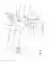
FIGS. 1 to 7 illustrate separate perspective views, taken from the same viewing position, of the inventive apparatus in seven subsequent steps of operation;
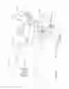
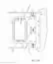
FIG. 8 is a perspective view, taken from a viewing position opposite to the one of the previous figures, of the inventive apparatus in the operating step of FIG. 3;
FIG. 9 illustrates a perspective view, taken from a viewing position opposite to the one of FIG. 4, of the inventive apparatus in the operating step of FIG. 4;
FIG. 10 illustrates a perspective view, from a viewing position opposite to the one of FIG. 5, of the inventive apparatus in the operating step of FIG. 5;
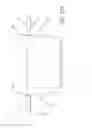
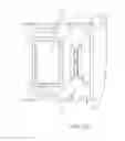
FIG. 11 illustrates the exploded view of the apparatus of FIG. 1;
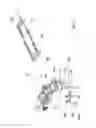
FIGS. 12A and 12B illustrate two schematic elevational views and plane projections on a vertical plane of a detail of the inventive apparatus, in two respective steps of operation;
FIGS. 13A and 13B illustrate two schematic plane views from above of a portion of the inventive apparatus in two subsequent steps of operation corresponding respectively to FIGS. 12A and 12B.
BEST MODE FOR CARRYING OUT THE INVENTION
With reference to the figures, an apparatus for filling with loose horticultural products each of a plurality of containers and/or small boxes, preferably made of plastic, in succession comprises:
-
- at least one transporting conveyor 1 that runs on a horizontal plane on a closed path;
- at least one moving structure arranged at the output edge 2 of said conveyor 1, and provided with displacement and engaging means that allow it to oscillate the container in an articulated manner as it will be described later.
Said moving structure includes:
-
- an oscillating frame 10 formed substantially in a “U” shape (see FIGS. 13A and 13B) and in which the open side 11 is suitable to position itself in front of said output edge 2 of said transporting conveyor 1;
- at least one, but preferably at least two blocking means 12, 13 supported by said oscillating frame 10.
The oscillating frame 10 is suitable to be rotated, by known means, in a plurality of reciprocally angular positions around a single axis “Z” integral with the apparatus and parallel to, and therefore integral with, said output edge 2, and specifically:
-
- from a first raised position, as in FIGS. 4 and 9, in which the plane of the loading aperture “V” of the container is inclined, at a maximum pre-defined angle “A”, with respect to the plane of said conveyor 1, and with said loading aperture “V” remaining contiguous to the output edge 2 of said conveyor;
- to subsequent working positions in which said container moves through progressively less inclined positions, until it reaches the position of FIGS. 1, 2, 3, 5, 10, or substantially horizontal (at the end or at the beginning of the filling step).
The blocking means 12 and 13, as shown, consist of respective partially concave jaws, with the concave surface turned toward the inside of the oscillating frame 10 and are arranged at the opposite internal sides of the frame, and specifically at the two sides 10A and 10B that make up the opposite arms of said oscillating frame 10 defined as “U” shaped.
Therefore, according to a preferred embodiment as shown in the figures, the assembly formed by the oscillating frame 10 and the jaws 12 and 13 is symmetrical with respect to a vertical plane passing through the centre line of the conveyor 1; the intersection of said vertical plane with said conveyor is shown in FIG. 1 by the cross-sectional line “X”.
FIGS. 13A and 13B, which illustrate schematically said two jaws 12, 13 viewed from above, also show that each of them is provided, in the relative central part, with a rectilinear profile 12A and 13A; said profiles are shaped and dimensioned so that each jaw can adapt itself around a corresponding opposite vertical side 20A, 20B of a container 20 inserted inside and in the central area of the oscillating frame 10.
Each of said jaws is provided with known displacement and engagement means, suitable to displace it, in a translational and rectilinear manner, through respective paths P1, P2, from a first position defined here as “open”, as in FIGS. 1, 12A and 13A, to a second position defined here as “closed”, as in FIGS. 3, 12B and 13B.
In the “open” position said jaws are drawn back and displaced toward said respective opposite arms of the “U” on the oscillating frame 10, which leaves the container 20 completely free and disengaged from the oscillating frame 10 and from the two jaws, as in FIGS. 2, 6, 12A and 13A; when said jaws are displaced to the “closed” position, they are displaced with a controlled and simultaneous, and preferably symmetrical, movement, toward the centre, and they close in toward the respective sides 20A and 20B of the container 20, which is thus caught between them; given the geometry of the components described and involved, and shown in the figures, it is evident that said jaws are always displaced with a motion which is orthogonal to the direction of movement of the transporting conveyor 1, shown by said cross-sectional line “X” in FIG. 13A.
Thus said jaws perform selectively and alternatively a rectilinear motion, moving reciprocally closer to each other and reciprocally apart from each other.
The reciprocal dimensions and the geometry of said container and of said jaws, and their relative movements, are such that when the container itself is in a suitable raised position, which will be better detailed later, the passage of said jaws from the “open” position to the “closed” position (see FIGS. 3, 12B, 13B) brings the jaws in contact with the sides 20A, 20B of the container in a particular position; in fact, as shown in FIGS. 12A and 12B, the containers used in the apparatus of the invention are empty parallelepiped containers, whose opposite sides 20A, 20B are provided, on the respective upper edges, with respective engaging rims 20A-A and 20B-B configured as outwardly and horizontal projections (with the container in a normal resting position on a horizontal plane) of the respective sides.
Said engaging rims, which resemble typical “collars”, work therefore like “handles” that are engaged by the respective jaws 12, 13 which insert immediately below the engaging rims and clasp them firmly.
In this operation, said jaws are limited to coming into contact with the respective sides 20A, 20B of the container 20 preventing to squeeze them, since the simple lifting of the jaws immediately brings the respective upper faces 12A, 13A (FIGS. 12A, 12B) into engagement with the lower faces of the respective engaging rims 20A-A and 20B-B, which in effect allows the lifting or partial rotation of the container without squeezing it, which is in fact the desired effect.
Preferably, in order to actuate in a controlled mode the movement and synchronism of said jaws, appropriate double-acting pneumatic or hydraulic cylinders 35, 36 (see FIGS. 1, 3) are arranged on said oscillating frame 10; such double-acting pneumatic or hydraulic cylinders 35, 36 offer an improvement in the operating speed of the jaws 12, 13 as well as a perfect synchronism of their movements, which is necessary to prevent the possibility that an asymmetric displacement of the jaws causes a displacement of the container from the correct position in the loading phase.
Advantageously, said oscillating frame 10 is operated in a rotational motion around said orthogonal axis “Z” by means of one or more hydraulic cylinders 40, 41, (see FIGS. 1, 4), preferably of double-acting type, each of which being engaged between a portion, preferably a rear portion 40A, 40B, of said oscillating frame, and a respective resistance point 40B, 41B, integral with the structure of said apparatus, as shown in FIGS. 1, 4 and 8.
Moreover, in order to pick said container 20 by selecting it from a succession of similar containers, the apparatus includes lifting means provided with a substantially flat lifting surface 45, shown in FIGS. 4, 8 and 9, arranged at and below said output edge 2 of said transporting conveyor 1 and suitable to selectively lift and lower one of said containers and/or small boxes in a controlled manner.
Said lifting surface 45 is operated, with known means, so as to be supplied, in a lowered position, with a single container at a time by suitable feeding means that supply said surface 45 with the individual separate containers.
After said surface 45 is loaded with a single container, it is lifted to a level in which the respective engaging rims 20A-A and 20B-B rise up to the level of said jaws 12, 13, and specifically up to the engaging level as previously explained, as is clearly shown in FIG. 2.
In effect, said surface 45 forms a simple hoisting table that lifts every container to a level suitable for the correct operation of said oscillating frame 10; in fact, the oscillating frame, after having held the respective engaging rims 20A-A and 20B-B (FIG. 3) by means of said jaws 12 and 13, is rotated toward the conveyor 1 so as to be set at the desired inclination (FIG. 4); the filling of the container begins immediately after the start of rotation of the frame, and continues during the whole phase of rotation of the same and, if necessary, even after the container has been rotated to the stable position at its maximum inclination.
When the filling of the container is completed, the oscillating frame returns in reverse rotation to its initial position, in which said container rests again on the surface 45, as in FIG. 5; immediately after this, the jaws 12 and 13 open and free the container 20 from the frame 10 (FIG. 6), and subsequently said surface 45 is lowered again to the starting position (FIG. 7), from where the newly filled container is removed, and in its place is brought an empty container to begin another filling cycle.
FIGS. 8, 9 and 10 illustrate, from a different perspective angle, the steps of FIGS. 3, 4 and 5, respectively, and thus their detailed explanation is omitted.
It will be readily understood by the skilled person that the basic function of said surface 45 is to bring each container in succession to the working position, and thus it works as a “loader”; the fact that it works only vertically is dictated by the requirement of taking up the least possible useful space on the horizontal plane.
It has to be noted that the apparatus of the invention utilizes three separate mechanisms, each of which performing a separate function:
-
- the oscillating frame 10 moves with a partial rotation, that is, an “oscillation” about the “Z” axis integral with the apparatus;
- the two jaws 12 and 13 move in synchronism with a reciprocal movement apart from and toward each other, and are displaced with respect to the opposite sides of said frame 10 by which they are supported. Thus it can be said that said jaws can perform a double movement: a movement of their own with respect to the frame and a motion induced by the oscillation of the frame with respect to the apparatus; however, for what concerns the control of said jaws, their movement is a simple alternating rectilinear movement of translation with respect to said frame 10 since they are supported by the frame 10;
- the third movement regards the lifting/lowering of the lifting surface 45. As explained above, said single functional assemblies are provided with respective operating means, known per se or explicitly described above.
However, in order to perform the general function required, said functional assemblies must be able to sequence their operating steps in a logical manner, thus also achieving a more effective step-by-step synchronization.
For this purpose, the apparatus is provided with known command and control means that process the control signals that must be sent to each of said functional assemblies to implement the designated method, which is made up of the following individual steps briefly described herebelow with reference to the enclosed figures:
-
- a) Loading the container 20 onto the lowered lifting surface 45, FIG. 1;
- b) Raising said lifting surface 45 and stopping it at the predetermined level, FIG. 2;
- c) Closing said jaws 12, 13 around the upper rims 20A-A and 20B-B of said container/small box 20, FIGS. 3, 8;
- d) Rotating said oscillating frame 10 to a predetermined inclination, FIGS. 4, 9;
- e) Actuating said transporting conveyor 1 for a time depending on at least one predefined external variable, or until a predefined moment, so as to ensure the desired filling of the container with the horticultural products, and subsequently stopping the conveyor 1. Said predefined variable, or said predefined moment, are implemented in a manner that is functional only to the purpose of ensuring the filling of the container; since they are per se known, they do not belong to the present invention; for the purpose of general information alone, it is pointed out that said predefined variable can be based on:
- a predefined time interval;
- the volume of the products loaded into said container 20;
- the weight of the products loaded into the container;
- the length of the travel of said conveyor, wherein the container is loaded between two subsequent stops;
- a photocell connected to said conveyor, or a functionally equivalent device, capable of measuring the filling level of the container.
As mentioned above, the transporting conveyor can also start to fill the container right at the start of its rotation phase:
It will be noted that the function identified as “e” in the above list of steps, and which does not have a representative figure of its own—that is, the programmed operation of the conveyor—is not a function included among the first three listed above; nevertheless it has been included because it must be sequenced and synchronized with the other functional assemblies described, so as to be able to carry out all the actions necessary for the purpose of filling each container as described; therefore this demonstrates the necessity that said command and control means do not control only the three functional assemblies described, but that they are integrated with the rest of the functional components of the whole apparatus.
In particular, the presence of means suitable to sense the presence, or the absence of products on the transporting conveyor, especially means like the above-mentioned photocell, offers the possibility of having an advantageous and improved functional mode; this consists of the fact that when said photocell senses the absence of products on the conveyor, the signal produced and transmitted by the same photocell can be used to interrupt both the movement of the conveyor itself, and also, or alternatively, the rotational movement of the oscillating frame and thus of the respective container. In practice, if there is no product detected on the conveyor, both the movement of the conveyor and the movement of the container can be temporarily stopped (as if placed on stand-by), until new product is sensed on the conveyor, which causes the automatic resumption of operation of the complete apparatus.
It must also be made clear that the geometrical architecture, the installation and the functionality of said jaws 12 and 13 can be validly and identically substituted by any means suitable to implement the same function, as for example a pair of tongs, or clamps, etc.
Claims
1. Apparatus for the filling with horti-fructural loose products of each of a plurality in series of containers or small boxes, and comprising:
at least one transporting conveyor moving on an horizontal plane with a motion on a closed path,
at least a moving structure arranged at the output edge of said conveyor, and provided with displacement and engaging means able of oscillating in an articulated way said container from:
a first raised position wherein the plane of the loading aperture of said container is inclined, at a maximum pre-defined n angle, with respect to the plane of said conveyor, said loading aperture maintained contiguous to said output edge of said transporting conveyor,
to successive working positions wherein said container takes progressively less inclined positions, until the horizontal position of said loading aperture,
wherein said conveyor, in said inclined positions of said container, is able of moving forward to said container so that, by gravity, said horti-fructural loose products fall into said container, wherein said moving structure comprises:
an oscillating frame, substantially shaped as an “U”, whose open side is apt of being placed in front of said output edge of said transporting conveyer,
blocking means engaged by said oscillating frame and able of selectively:
- being arranged, at least partially, around and into contact to the outer perimeter of said container, and of being disengaged from said outer perimeter.
2. Apparatus according to claim wherein said blocking means do comprise:
one or more jaws arranged inside said oscillating frame and able of being shifted with a translatory motion with respect to the frame itself and be engaged and selectively be disengaged in a controlled and simultaneous way, and on the same direction but with opposed sense, against two opposed rims of said container, each of said opposed rims being arranged on a respective plane substantially parallel to the motion direction of said transporting conveyor.
3. Apparatus according to claim 2, wherein said jaws are partially concave to the inner portion of said oscillating frame, and are placed on the opposed sides of it.
4. Apparatus according to claim 3, wherein said oscillating frame is apt of rotating on an axis:
orthogonal to said motion direction of said transporting conveyor,
and basically firm to the position of said outlet edge.
5. Apparatus according to claim 4, wherein said oscillating frame is able to be rotated around said orthogonal axis through one or more hydraulic cylinders, preferably by double effect, each of which being engaged between a portion which preferably is a rear portion, of said oscillating frame, and a respective resistance point, which is solid to the structure of said apparatus.
6. Apparatus according to claim 1, wherein it comprises a lifting means:
provided with a lifting surface which is basically flat,
arranged in correspondence and below said output edge of said transporting conveyor,
able of selectively lifting and lowering one of said containers to the level wherein the respective upper rims are raised to the level of said jaws .
7. Apparatus according to claim 1, wherein pneumatic or hydraulic means are arranged, which are able of acting said jaws, and in that said means are mounted on said oscillating frame.
8. Apparatus according to claim 1, wherein it comprises command and control means of said oscillating frame, of said jaws and of said lifting surface able of acting them according to the sequence which includes the following steps:
a) loading the container on said lifting surface when lowered,
b) raising said lifting surface, and subsequent stopping it,
c) closing said jaws around the upper rims of said container,
d) rotating said oscillating frame to a pre-determined inclination,
e) acting said transportation conveyor for a definite time interval depending on at least an external and pre-defined variable, and successive stopping of said conveyor,
f) reverse rotation of said oscillating frame to the initial position,
g) opening of said jaws,
h) lowering of said lifting surface,
i) unloading said container from said lifting surface.
9. Apparatus according to claim 1, wherein said external and pre-defined variable is, as alternative:
a pre-defined time interval,
the volume of the products loaded into said container,
the weight of the products loaded into said container,
the length of the path of said conveyor, whose load is introduced into said container between successive stops,
a photocell or a functionally equivalent device, able of measuring the filling level of the container.
10. Apparatus according to claim 1, wherein it comprises command and control means able:
of activating the motion of said conveyor at the beginning of the rotation of said oscillating frame,
and of causing the activation of said hydraulic means so as said oscillating frame is progressively rotated towards the starting position during the operation of said conveyor.
11. Apparatus according to claim 9, wherein the operation of said conveyor and/or the rotational motion of said oscillating frame are automatically made dependent on the detection of the presence/absence of such products on the conveyor itself.
12. Apparatus according to claim 2, wherein it comprises a lifting means:
provided with a lifting surface which is basically flat,
arranged in correspondence and below said output edge of said transporting conveyor,
able of selectively lifting and lowering one of said containers to the level wherein the respective upper rims are raised to the level of said jaws.
13. Apparatus according to claim 3, wherein it comprises a lifting means:
provided with a lifting surface which is basically flat,
arranged in correspondence and below said output edge of said transporting conveyor,
able of selectively lifting and lowering one of said containers to the level wherein the respective upper rims are raised to the level of said jaws.
14. Apparatus according to claim 4, wherein it comprises a lifting means:
provided with a lifting surface which is basically flat,
arranged in correspondence and below said output edge of said transporting conveyor,
able of selectively lifting and lowering one of said containers to the level wherein the respective upper rims are raised to the level of said jaws.
15. Apparatus according to claim 5, wherein it comprises a lifting means:
provided with a lifting surface which is basically flat,
arranged in correspondence and below said output edge of said transporting conveyor,
able of selectively lifting and lowering one of said containers to the level wherein the respective upper rims are raised to the level of said jaws.
16. Apparatus according to claim 2, wherein pneumatic or hydraulic means are arranged, which are able of acting said jaws, and in that said means are mounted on said oscillating frame.
17. Apparatus according to claim 3, wherein pneumatic or hydraulic means are arranged, which are able of acting said jaws, and in that said means are mounted on said oscillating frame.
18. Apparatus according to claim 4, wherein pneumatic or hydraulic means are arranged, which are able of acting said jaws, and in that said means are mounted on said oscillating frame.
19. Apparatus according to claim 5, wherein pneumatic or hydraulic means are arranged, which are able of acting said jaws, and in that said means are mounted on said oscillating frame.
20. Apparatus according to claim 6, wherein pneumatic or hydraulic means are arranged, which are able of acting said jaws, and in that said means are mounted on said oscillating frame.
Images & Drawings included:


Sources:
- United States Patent and Trademark Office - verify current appl. status at the USPTO↗
Recent applications in this class:
- » 20240409260 2024-12-12
A PACKAGING DEVICE AND SORTING SYSTEM FOR DIRECTIONAL PACKAGING OF PRODUCTS, SUCH AS VEGETABLES AND FRUIT, AND A METHOD THEREFOR - » 20220267039 2022-08-25
Fruit packaging tray, apparatus and process - » 20180162571 2018-06-14
Filling device for filling a holder with vulnerable products, and method therefor - » 20170121042 2017-05-04
Machine for filling containers with fruit or vegetable products - » 20120005986 2012-01-12
Apparatus for boxing fruit - » 20080223000 2008-09-18
PACKING APPARATUS - » 20080175961 2008-07-24
Packaged-corn-on-the-cob - » 20080066429 2008-03-20
Guiding, distributing and filling device, and method for use thereof - » 20060288880 2006-12-28
Gentle dry bin filler - » 20050028495 2005-02-10
Automatic packing device for the filling of containers by means of superposed layers of products, in particular fruits such as oranges
Recent applications for this Assignee:
- » 20170347690 2017-12-07
Apparatus for dispensing and mixing cold beverages - » 20170247198 2017-08-31
Conveyor apparatus for the transportation and weighing of agricultural products - » 20170240308 2017-08-24
Apparatus for dosing and packaging agricultural products - » 20170188619 2017-07-06
Apparatus for the separation of agricultural products - » 20160200469 2016-07-14
IMPROVED APPARATUS FOR AUTOMATICALLY OPENING CRATES OF DIFFERENT DIMENSIONS - » 20150150299 2015-06-04
Apparatus for separating agricultural products - » 20140190123 2014-07-10
Plant for manual packaging of products, in particular fruit and vegetable products - » 20140144818 2014-05-29
Plant for selection of crates for vegetable products according to their degree of cleanliness