Method for triggering a driver assistance function upon detection of a brake light by a camera
US20160110620A1
2016-04-21
14/777,662
2014-03-07
✅ Patent granted
US 9,864,916 B2
2018-01-09
WO; PCT/DE2014/200116; 20140307
WO; WO2014/154213; 20141002
Hee-Yong Kim
W. F. Fasse
2034-08-24
Abstract:
The invention relates to a method for triggering a driver assistance function of a vehicle, in which image data of that part of the surroundings of the vehicle which is in front of the vehicle is generated by means of a camera and supplied to an analyzing unit for the purpose of analysis and the driver assistance function is triggered upon detection of a stop light (1) of a further vehicle (10) detected as an object, said stop light (1) being contained in the image data. According to the invention, at least one geometric region of a detected object (10) is determined in the image data, the pixels of said region essentially exhibiting the highest brightness values in the image data and the spectral color red, and the geometric region is detected as a raised stop light (1) of the further vehicle (10) if the geometric region is detected to be positioned essentially in the middle of the horizontal structure of the detected object (10).
Inventors:
- Adrian BOTUSESCU 2 🇷🇴 Timisoara, Romania
- Radu CIUCUR 1 🇷🇴 Timisoara, Romania
- Nicolae PAHONTU 3 🇷🇴 Campia Turzii, Romania
- Sabin CATANA 1 🇷🇴 Timisoara, Romania
- Valentin VINTILA 1 🇷🇴 Timisoara, Romania
Assignee:
- CONTINENTAL AUTOMOTIVE GMBH 2,462 🇩🇪 Hannover, Germany
Applicant:
Interested in similar patents?
Get notified when new applications in this technology area are published.
Classification:
B60Q9/008 » CPC further
Arrangement or adaptation of signal devices not provided for in one of main groups - , e.g. haptic signalling for anti-collision purposes
G06T7/40 IPC
Image analysis Analysis of texture
H04N7/185 » CPC further
Television systems; Closed circuit television systems, i.e. systems in which the signal is not broadcast for receiving images from a single remote source from a mobile camera, e.g. for remote control
G06K9/00 IPC
Methods or arrangements for recognising patterns
B60T7/22 » CPC further
Brake-action initiating means for automatic initiation; for initiation not subject to will of driver or passenger initiated by contact of vehicle, e.g. bumper, with an external object, e.g. another vehicle, or by means of contactless obstacle detectors mounted on the vehicle
B60Q9/00 IPC
Arrangement or adaptation of signal devices not provided for in one of main groups - , e.g. haptic signalling
H04N7/18 IPC
Television systems Closed circuit television systems, i.e. systems in which the signal is not broadcast
B60T2201/022 » CPC further
Particular use of vehicle brake systems; Special systems using also the brakes; Special software modules within the brake system controller; Active or adaptive cruise control system; Distance control Collision avoidance systems
G06T7/90 » CPC further
Image analysis Determination of colour characteristics
B60T2210/32 » CPC further
Detection or estimation of road or environment conditions; Detection or estimation of road shapes; Environment conditions or position therewithin Vehicle surroundings
B60Q1/26 IPC
Arrangement of optical signalling or lighting devices, the mounting or supporting thereof or circuits therefor the devices being primarily intended to indicate the vehicle, or parts thereof, or to give signals, to other traffic
B60T17/22 » CPC further
Component parts, details, or accessories of power brake systems not covered by groups , or , or presenting other characteristic features; Safety devices; Monitoring Devices for monitoring or checking brake systems; Signal devices
Description
The invention relates to a method according to the Preamble of Patent Claim 1.
A generic method is known from DE 10 2009 025 545 A1, in which that part of the surroundings of a vehicle which is in front of the vehicle is covered by means of a vehicle camera and analyzed with respect to the detection of flashing signals (stop lights in particular) in the image data. If a stop light is detected, automatic driver assistance control (e.g., longitudinal control and/or lateral control) is performed. DE 10 2009 025 545 A1 also proposes outputting information signals to a visual display device and/or an acoustic output device if a stop light is detected. Stop lights are detected as a result of the subdivision of the image data into sections (bottom central section, bottom left section, bottom right section) so that also a raised stop light (third stop light) can be detected. Furthermore, color differentiation is performed for the purpose of distinguishing the red stop lights from the orange or yellow flashing lights.
DE 10 2009 025 545 A1 also describes a method for the detection of stop light systems by means of an analysis of image data of that part of the surroundings of the vehicle which is in front of the vehicle, said image data being acquired by means of a vehicle camera. If a vehicle is detected in the image by means of an analyzing unit connected to the camera system, an image sector associated with this vehicle is subdivided into a left section, a central section, and a right section. On the basis of brightness values of the pixels contained in these sections, at least one brightest image segment is extracted from each of these sections and checked in each case to see whether the extracted image segment from the left section and the extracted image segment from the right section are equally sized and situated at the same height and whether the brightest image segment from the central section is situated in a higher and centered position between the brightest image segments from the left and right sections. If this is the case, the analyzing unit outputs a stop light signal that causes the stop light of the vehicle to be activated.
The purpose of equipping vehicles with a third stop light (so-called raised stop light) consists in increasing the attention of a driver of a following vehicle in order to reduce the risk of rear-end collisions. Especially when driving in a convoy of vehicles, drivers are required to be very careful so that braking operations performed by vehicles driving ahead of the vehicle driving immediately ahead of the ego-vehicle can be detected early enough since the stop lights of those braking vehicles are often covered by the vehicle driving immediately ahead of the ego-vehicle so that, e.g., only the third stop light is visible.
The object of the invention is to further develop a method of the type mentioned at the beginning in such a manner that the driver is assisted in detecting stop lights of vehicles driving ahead of the ego-vehicle in a convoy of vehicles, the stop lights of those vehicles driving ahead being partially covered by the vehicle driving immediately ahead of the ego-vehicle.
This object is achieved by a method with the features of Patent Claim 1, Patent Claim 3, and Patent Claim 4.
According to the inventive solution mentioned first, such a method for triggering a driver assistance function of a vehicle, in which image data of that part of the surroundings of the vehicle which is in front of the vehicle is generated by means of a camera and supplied to an analyzing unit for the purpose of analysis and the driver assistance function is triggered upon detection of a stop light of a further vehicle detected as an object, said stop light being contained in the image data, is characterized in that
-
- at least one geometric region of a detected object is determined in the image data, the pixels of said region essentially exhibiting the highest brightness values in the image data and the spectral color red, and
- the geometric region is detected as a raised stop light of the further vehicle if the geometric region is detected to be positioned essentially in the middle of the horizontal structure of the detected object.
It is thus possible to detect the driving state of vehicles driving ahead of the ego-vehicle in the convoy of vehicles (particularly, the braking state of those vehicles generated by the driver by actuating the brake pedal) on the basis of the raised stop lights of those vehicles if the left and right stop lights of those vehicles are covered by a vehicle driving immediately ahead of the ego-vehicle or by other objects. In particular, the statutory provision stipulating that such a raised stop light must be arranged in the middle of the rear side of the vehicle is made use of for the purpose of detecting such a stop light.
According to an advantageous realization of the invention, the geometric region is detected as a raised stop light of the further vehicle if the geometric region is additionally positioned at least at a predetermined height above the pavement, thus making use of the statutory provision stipulating that such a raised stop light must be mounted on the rear side of the vehicle at least 850 mm above the pavement.
Furthermore, according to the solution mentioned second, the inventive method is characterized in that
-
- at least one geometric region of a detected object is determined in the image data, the pixels of said region essentially exhibiting the highest brightness values and the spectral color red, and
- the geometric region is detected as a raised stop light of the further vehicle if the geometric region is positioned at least at a predetermined height above the pavement.
This inventive solution provides a further possibility of detecting the driving state of vehicles driving ahead of the ego-vehicle in the convoy of vehicles (particularly, the braking state of those vehicles generated by the driver by actuating the brake pedal) on the basis of the raised stop lights of those vehicles if the left and right stop lights of those vehicles are covered by a vehicle driving immediately ahead of the ego-vehicle or by other objects. In particular, the statutory provision stipulating that the raised stop light must be arranged on the rear side of the vehicle at a predetermined minimum height of 850 mm above the pavement is made use of for the purpose of detecting such a stop light.
The inventive solution mentioned third is characterized in that
-
- at least one geometric region of a detected object is determined in the image data, the pixels of said region essentially exhibiting the highest brightness values and the spectral color red, and
- the geometric region is detected as a raised stop light of the further vehicle if the geometric region is positioned at a predetermined distance below a detected rear window of the further vehicle.
Finally, this inventive solution provides a further possibility of detecting the driving state of vehicles driving ahead of the ego-vehicle in the convoy of vehicles (particularly, the braking state of those vehicles generated by the driver by actuating the brake pedal) on the basis of the raised stop lights of those vehicles if the left and right stop lights of those vehicles are covered by a vehicle driving immediately ahead of the ego-vehicle or by other objects. In particular, the statutory provision stipulating that the raised stop light must be arranged on the rear side of the vehicle at a distance of not more than 150 mm below the rear window of the vehicle is made use of for the purpose of detecting such a stop light.
According to an advantageous further development of the invention according to the second solution and the third solution, the geometric region is detected as a raised stop light of the further vehicle if the geometric region is additionally positioned essentially in the middle of the horizontal structure of the detected object. This condition takes the statutory provision stipulating that the raised stop light must be arranged in the middle of the tail of the vehicle into account.
The inventive methods may be improved if the left stop light and the right stop light are not covered at the same time but if, e.g., only the left stop light is covered due to an offset vehicle driving ahead of the ego-vehicle so that both the raised stop light and the right stop light of a vehicle driving further ahead of the ego-vehicle in a convoy of vehicles can be detected by the camera.
According to an advantageous further development, the further geometric region is detected in the image data as a left stop light or a right stop light if the distance between the raised stop light and the further geometric region is the hypotenuse of a right triangle and the length of the vertical cathetus and the length of the horizontal cathetus of the right triangle are in defined proportion to each other. Thus, the geometric arrangement of the raised stop light and of the left stop light or the right stop light on the rear side of the vehicle is advantageously made use of. Preferably, according to said defined proportion, the vertical cathetus is shorter than the horizontal cathetus of the right triangle or the vertical cathetus is not longer than three times the length of the horizontal cathetus of the right triangle.
In the inventive method, an acoustic and/or visual and/or haptic warning are/is outputted as a driver assistance function upon detection of a stop light. Additionally or alternatively, an intervention in the longitudinal dynamics and/or lateral dynamics of the vehicle (preferably, the initiation of a braking operation) may be performed as a driver assistance function.
In the following, the invention will be explained in greater detail with reference to the attached figures, in which
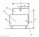
FIG. 1 shows a schematic representation of vehicles driving ahead as viewed by a camera of a following vehicle for explaining exemplary embodiments of the inventive method;
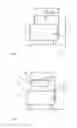
FIG. 2 shows a further schematic representation of vehicles driving ahead as viewed by a camera of a following vehicle for explaining further exemplary embodiments of the inventive method; and
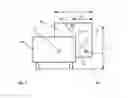
FIG. 3 shows a further schematic representation of vehicles driving ahead as viewed by a camera of a following vehicle for explaining further exemplary embodiments of the inventive method.
FIGS. 1 through 3 show the image of image data acquired by a camera of a following vehicle, said image data being data of that part of the surroundings which is in front of the vehicle, wherein vehicles driving ahead 10 and 20 can be seen in the visual range of the camera, wherein FIGS. 1 and 2 show a situation in which a right stop light 1.1 and a left stop light 1.2 are covered by a vehicle 20 positioned between the following vehicle equipped with the camera and the vehicle 10. The image data acquired by the camera is supplied to an analyzing unit for the purpose of analysis.
First Exemplary Embodiment
Analysis is performed by determining a geometric region of a detected object (of the vehicle 10 in the present case) in the image data, the pixels of said region essentially exhibiting the highest brightness values in the image data and the spectral color red.
A second condition for detecting this geometric region as a raised stop light 1 is that this geometric region must be detected to be positioned essentially in the middle of the horizontal structure of the detected object 10. For this purpose, a determination of the width b of the vehicle 10 and a check as to whether this geometric region exhibits a distance b1 from the lateral edges of the object 10 are performed.
To improve the accuracy of detection of the raised stop light 1, a third condition may be checked. This third condition is that the geometric region must be positioned at least at a predetermined height h1 (850 mm) above the pavement 30. This complies with the statutory provision stipulating that such a raised stop light must be mounted on the rear side of the vehicle 10 at least 850 mm above the pavement.
The detection of such a raised stop light 1 results in the assumption that this vehicle 10 is performing a braking operation. Therefore, an acoustic and/or visual and/or haptic warning are/is outputted, as a driver assistance function, to the driver of the following vehicle. Additionally or alternatively, an intervention in the longitudinal dynamics and/or lateral dynamics of the vehicle (particularly, the initiation of a braking operation) may be performed as a driver assistance function.
Second Exemplary Embodiment
In this exemplary embodiment referring to FIG. 1, image data analysis starts, as in the first exemplary embodiment, with determining a geometric region of a detected object (of the vehicle 10 in the present case) as a first condition for detecting a raised stop light, the pixels of said region essentially exhibiting the highest brightness values in the image data and the spectral color red.
A second condition for detecting this geometric region as a raised stop light 1 is that the geometric region must be positioned at least at a predetermined height h1 (850 mm) above the pavement 30. This again complies with the statutory provision such a raised stop light 1 must comply with.
To improve the accuracy of detection of the raised stop light 1, a third condition may be checked. This third condition is that the geometric region must be positioned essentially in the middle of the horizontal structure of the detected object 10. For this purpose, a determination of the width b of the vehicle 10 and a check as to whether this geometric region exhibits a distance b1 from the lateral edges of the object 10 are performed.
The detection of such a raised stop light 1 results in the assumption that this vehicle 10 is performing a braking operation. Therefore, an acoustic and/or visual and/or haptic warning are/is outputted, as a driver assistance function, to the driver. Additionally or alternatively, an intervention in the longitudinal dynamics and/or lateral dynamics of the vehicle (particularly, the initiation of a braking operation) may be performed as a driver assistance function.
Third Exemplary Embodiment
In this third exemplary embodiment referring to FIG. 2, image data analysis starts, as in the first and second exemplary embodiments, with determining a geometric region of a detected object (of the vehicle 10 in the present case) as a first condition for detecting a raised stop light, the pixels of said region essentially exhibiting the highest brightness values in the image data and the spectral color red.
A second condition for detecting this geometric region as a raised stop light 1 is complied with if this geometric region is positioned at a predetermined distance a (not more than 150 mm) below a detected rear window 11 of the further vehicle 10. This requires the detection of such a rear window 21 of the vehicle driving ahead 10 by means of the analyzing unit. The statutory provision stipulating that the raised stop light must be arranged on the rear side of the vehicle at a distance of not more than 150 mm below the rear window of the vehicle is made use of for the purpose of detecting such a stop light.
To improve the accuracy of detection of the raised stop light 1, a third condition may be checked. This third condition is that the geometric region is positioned essentially in the middle of the horizontal structure of the detected object 10. For this purpose, a determination of the width b of the vehicle 10 and a check as to whether this geometric region exhibits a distance b1 from the lateral edges of the object 10 are performed.
The detection of such a raised stop light 1 results in the assumption that this vehicle 10 is performing a braking operation. Therefore, an acoustic and/or visual and/or haptic warning are/is outputted, as a driver assistance function, to the driver. Additionally or alternatively, an intervention in the longitudinal dynamics and/or lateral dynamics of the vehicle (particularly, the initiation of a braking operation) may be performed as a driver assistance function.
Fourth Exemplary Embodiment
This fourth exemplary embodiment refers to FIG. 3, which shows that the vehicle driving ahead 2 is not covering both stop lights 1.1 and 1.2 but only the left stop light 1.2 so that the right stop light 1.1 can be detected by the camera of the following vehicle.
Analysis starts with detecting geometric regions in the image data of the region of a detected object (of the vehicle 10 in the present case) as a first condition, the pixels of said regions essentially exhibiting the highest brightness values in the image data and the spectral color red. If two such regions are detected, a check as to whether one of the two geometric regions is a raised stop light 1 is performed on the basis of the conditions explained in the exemplary embodiments above. If this is the case, the assumption that the two detected geometric regions are a raised stop light 1 and a right stop light 1.1 is proceeded on.
To improve the accuracy of detection of the raised stop light 1 and the right stop light 1.1, a further condition is checked according to FIG. 3, wherein a check as to whether the distance between the raised stop light 1 and the further geometric region 1.1 (right stop light) is the hypotenuse H of a right triangle D and the length of the vertical cathetus K1 and the length of the horizontal cathetus K2 of the right triangle D are in defined proportion to each other is performed. Thus, the geometric arrangement of the raised stop light and of the left stop light or the right stop light on the rear side of the vehicle is advantageously made use of. According to said defined proportion, the vertical cathetus K1 is shorter than the horizontal cathetus K2 of the right triangle D or the vertical cathetus K1 is not longer than three times the length of the horizontal cathetus K2 of the right triangle D.
The detection of such a raised stop light 1 and the simultaneous detection of a right stop light 1.1 result in the assumption that this vehicle 10 is performing a braking operation. Therefore, an acoustic and/or visual and/or haptic warning are/is outputted, as a driver assistance function, to the driver. Additionally or alternatively, an intervention in the longitudinal dynamics and/or lateral dynamics of the vehicle (particularly, the initiation of a braking operation) may be performed as a driver assistance function.
REFERENCE NUMERALS
1 raised stop light
1.1 right stop light
1.2 left stop light
10 further vehicle
11 rear window of vehicle 10
20 vehicle
30 pavement
Claims
1-11. (canceled)
12. A method of triggering a driver assistance function of a vehicle, in which image data of a part of surroundings in front of the vehicle is generated by a camera and supplied to an analyzing unit for analysis, and the driver assistance function is triggered upon detection of a brake light of a further vehicle detected as an object in the image data, said brake light being contained in the image data, further comprising:
detecting at least one geometric region of the further vehicle in the image data, wherein pixels of said region exhibit a spectral color red and approximately highest brightness values in the image data,
determining that the geometric region is an illuminated raised brake light of the further vehicle if the geometric region is detected as having at least one of the following positioning features in the image data;
(a) a first positioning feature wherein the geometric region is positioned at least approximately in a horizontal middle of a horizontal structure of the further vehicle,
(b) a second positioning feature wherein the geometric region is positioned at or above a predetermined height above a roadway surface detected in the image data, or
(c) a third positioning feature wherein the geometric region is positioned at or below a predetermined distance below a rear window of the further vehicle detected in the image data, and
triggering the driver assistance function in response to said determining that the geometric region is the illuminated raised brake light.
13. The method according to claim 12, wherein the geometric region is determined to be the illuminated raised brake light if the geometric region is detected as having at least the first positioning feature.
14. The method according to claim 13, wherein the geometric region is determined to be the illuminated raised brake light only if the geometric region is detected as having at least both the first positioning feature and the second positioning feature.
15. The method according to claim 14, wherein the geometric region is determined to be the illuminated raised brake light only if the geometric region is detected as having all three of the first positioning feature, the second positioning feature and the third positioning feature.
16. The method according to claim 12, wherein the geometric region is determined to be the illuminated raised brake light if the geometric region is detected as having at least the second positioning feature.
17. The method according to claim 16, wherein the geometric region is determined to be the illuminated raised brake light only if the geometric region is detected as having at least both the second positioning feature and the third positioning feature.
18. The method according to claim 12, wherein the geometric region is determined to be the illuminated raised brake light if the geometric region is detected as having at least the third positioning feature.
19. The method according to claim 18, wherein the geometric region is determined to be the illuminated raised brake light only if the geometric region is detected as having at least both the first positioning feature and the third positioning feature.
20. The method according to claim 12, further comprising detecting a further geometric region in the image data and determining that the further geometric region is a left brake light or a right brake light of the further vehicle.
21. The method according to claim 20, wherein the further geometric region is determined to be the left brake light or the right brake light if a distance between the raised brake light and the further geometric region forms a sloping hypotenuse of a virtual right triangle, and a length of a vertical leg and a length of a horizontal leg of the virtual right triangle are in a pre-defined proportion to one another.
22. The method according to claim 21, wherein according to said pre-defined proportion, the vertical leg is shorter than the horizontal leg of the virtual right triangle.
23. The method according to claim 21, wherein according to said pre-defined proportion, the vertical leg is at most three times as long as the horizontal leg of the virtual right triangle.
24. The method according to claim 12, wherein the driver assistance function comprises outputting to a driver of the vehicle at least one of an acoustic warning, a visual warning, or a haptic warning.
25. The method according to claim 12, wherein the driver assistance function comprises performing an automatic intervention in controlling at least one of longitudinal dynamics or lateral dynamics of the vehicle.
26. The method according to claim 25, wherein the automatic intervention comprises automatically actuating brakes of the vehicle.
Images & Drawings included:
Sources:
- United States Patent and Trademark Office - verify current appl. status at the USPTO↗
Recent applications in this class:
- » 20230154200 2023-05-18
Probabilistic modular lane transition state estimation - » 20230073038 2023-03-09
Hierarchical processing of traffic signal face states - » 20230047947 2023-02-16
Determination of traffic light orientation - » 20220414388 2022-12-29
System and method for determining if a vehicle is parked - » 20220350995 2022-11-03
Data driven dynamically reconfigured disparity map - » 20220261583 2022-08-18
End-to-end signalized intersection transition state estimator with scene graphs over semantic keypoints - » 20220245387 2022-08-04
END-TO-END MONOCULAR 2D SEMANTIC KEYPOINT DETECTOR AND TRACKER LEARNING - » 20220222476 2022-07-14
Method and system for recognizing traffic lights using a high-precision map - » 20220198204 2022-06-23
Systems and methods for traffic light detection and classification - » 20220180108 2022-06-09
Light emitting diode flicker mitigation
Recent applications for this Assignee:
- » 20250006057 2025-01-02
VEHICLE-EXIT ASSIST APPARATUS - » 20240312120 2024-09-19
METHOD AND DEVICE FOR PROVIDING A VISUALIZATION OF A VEHICLE, AND VEHICLE - » 20240295913 2024-09-05
ELECTRONIC DEVICE AND METHOD OF RESPONDING TO A TRIGGER TO WAKE UP - » 20240126118 2024-04-18
Display system and method for operating a display system - » 20240103589 2024-03-28
Frame for an electro-optical display and electro-optical display having a frame - » 20240103348 2024-03-28
Device for securing an optical device - » 20240103153 2024-03-28
Distance measuring system - » 20240100956 2024-03-28
Control unit circuit for a motor vehicle, motor vehicle and operating method for the control unit circuit - » 20240053161 2024-02-15
Method for predicting a velocity profile of a vehicle - » 20230356682 2023-11-09
Method for adapting a triggering algorithm of a personal restraint device and control device for adapting a triggering algorithm of a personal restaint device