DEMOUNTABLE BRACKET, TABLET-DESK HOLDER ON SEATS
US20160113392A1
2016-04-28
14/803,528
2015-07-20
Abstract:
A demountable bracket, for holding tablet-desks on seats; that consists of a main body (1) that holds the tablet-desk (T) and with a general “L” configuration that has arranged permanently on its horizontal wing (11) a first anchorage part (2) and on its vertical wing (12) a second anchorage part (3); with the particularity that both anchorage parts (2), (3) have respective strategic shapes and are strategically oriented to mount/demount this assembly on a horizontal tube (A1) and on a vertical tube (A2) of the frame (A) of the seat without auxiliary tools or complex handling.
Interested in similar patents?
Get notified when new applications in this technology area are published.
Classification:
A47B23/02 » CPC main
Bed-tables; Trays; Reading-racks; Book-rests, i.e. items used in combination with something else releasably mounted on the bedstead or another item of furniture
A47B5/04 » CPC further
Suspended or hinged panels forming a table; Wall tables foldable
A47B83/02 » CPC further
Combinations comprising two or more pieces of furniture of different kinds Tables combined with seats
Description
CROSS REFERENCE TO RELATED APPLICATION
This Application claims the priority of Spanish Patent Application No. U201431399 filed on Oct. 28, 2014, which is incorporated by reference herein.
OBJECT OF THE INVENTION
The object of the invention refers to a demountable bracket, tablet-desk holder specifically on chairs and, in general, on seats (modular or not) of employees, such as in educational centres or meeting places where said seats use tablets as a mini-desk to facilitate the taking of notes.
BACKGROUND OF THE INVENTION
In the current state of the art, tablet-desks mounted on the frame of seats are already known.
In early technology, these tablet-desks were mounted permanently on the frame of the seat that had to present a characteristic structure for this purpose.
In a more recent technology, tablet-desks are mounted on the frame of the seat with the possibility of unfolding when used and folding when not used. For example, among others, documents ES1029256, ES2294879 (of the applicant), U.S. Pat. No. 6,073,997 and U.S. Pat. No. 6,224,149 refer to devices for folding/unfolding of tablet-desks on seats.
One unresolved problem in the known technology, regardless of whether the tablet-desks are of the folding type or not, with respect to the structure/frame of the seat, is centred on the fact that they can only be applied on seats with arm rests.
Another unresolved problem in the known technology is that the tablet-desks cannot be demounted/separated from the frame of the seats; that is to say, a seat with tablet-desk will always have it (although it can be folded so that it does not obstruct or interfere when the seat is used simply as such), as demounting the tablet-desk from the seat frame requires auxiliary tools, considerable time and/or specialized labour.
DESCRIPTION OF THE INVENTION
The object of the invention solves these problems; it proposes a simply structured bracket that holds the tablet-desk and can be mounted/demounted on the frame of any seat quickly and without any auxiliary tools. It is characterized in that:
-
- it consists of a main body, holder of the tablet-desk, with general “L” configuration, which has fastened on one of its wings, a first anchorage part and on the other wing, a second anchorage part; with the particularity that both anchorage parts have strategic shapes and are strategically oriented to mount/demount this assembly on the frame of the seat quickly and without auxiliary tools or complex handling;
- The first anchorage part defines an upper longitudinal recess provided with a wall/stop at one of its bases and a lower longitudinal recess, elastically deformable for mounting/demounting on a horizontal tube of the frame of the seat by elastic deformation;
- The second anchorage part defines two arched arms that emerge opposite each other, linearly lagging, delimiting between them an opening, and coaxial to each other, delimiting in continuity a housing for mounting/demounting on a vertical tube of the seat frame;
- The cited means for permanently mounting the first anchorage part on the horizontal wing of the main body are orifices made in the internal wall common to both longitudinal recesses to insert screws into them that are tapped in the horizontal wing of the main body;
- The cited means for permanently mounting the second anchorage part on the vertical wing of the main body are orifices—made in a portion of seat—to insert screws into them that are tapped in the vertical wing of the main body; and
- particularly, the cited main body is tubular.
For the purposes of the invention, it makes no difference:
-
- that the tablet-desk is arranged on the main body permanently or in a manner that it can be folded with respect to it;
- that the seat has or does not have an arm support. It is required that the arm support (in the case that the seat has an arm support) not interfere with the trajectory of the main body or with the anchorage parts in their movements for mounting/demounting of the assembly on the frame of the seat.
Other configurations and advantages of the invention can be deduced from the following description and from the dependent claims.
DESCRIPTION OF THE DRAWINGS
To better understand the object of the invention, in the attached figures a preferential form of embodiment is represented, subject to accessory changes that do not essentially change it. In this case:
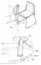
FIG. 1 represents a general schematic view and its enlarged detail of the bracket that is the object of the invention, with the anchorage parts (2), (3) fastened operationally on the respective wings (11), (12) of the main body (1) and all of it demounted from the frame (A) of a chair.
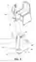
FIG. 2 represents a general schematic view and its enlarged detail, similar to the previous figure with the anchorage parts (2), (3) fastened operationally on the respective wings (11), (12) of the main body (1) and all of it mounted on the frame (A) of a chair.
Also represented in these figures is a folded tablet-desk (T), arranged on the vertical wing (12) of the main body (1).
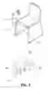
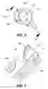
FIG. 3 represents a general schematic view in perspective of the first anchorage part (2), to observe its configuration and particularities.
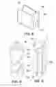
FIG. 4 represents a general schematic view in frontal perspective of the second anchorage part (3), to observe its configuration and particularities.
FIG. 5 represents a general schematic view in rear perspective of the second anchorage part (3), to observe its configuration and particularities.
FIG. 6 represents a plan view of the second anchorage part (3).
FIG. 7 represent a section, according to indication A:A of FIG. 6.
DESCRIPTION OF A PREFERENTIAL EMBODIMENT
The following is a description of an example of practical, non-limiting embodiment of this invention. Other ways of embodiment in which accessory changes which do not essentially alter it are introduced are in no way disregarded.
The object of the invention is a demountable bracket, tablet-desk (T) holder that can be mounted/demounted on the frame (A) of any seat quickly and without any auxiliary tools.
In conformity with the invention, the demountable bracket proposed consists basically of:
-
- a main body (1);
- a first anchorage part (2); and
- a second anchorage part (3);
According to the embodiment represented, the main body (1) is tubular, with general “L” configuration. It has means to permanently mount on one of its wings (11) said first anchorage part (2) and on its other wing (12) said second anchorage part (3). In operating position, the wing (11) is arranged horizontally, joined to a horizontal tube (A1) of the frame (A) of the seat; and the wing (12) is arranged vertically, joined to a vertical tube (A2) of the frame (A) of the seat.
According to the embodiment represented, the cited means for permanently mounting the first anchorage part (2) on the horizontal wing (11) of the main body (1) are orifices made in the internal wall (20)—common to both longitudinal recesses (21), (22)—to insert into them screws that are tapped in the horizontal wing (11) of the main body (1).
According to the embodiment represented, the cited means for permanently mounting the second anchorage part (3) on the vertical wing(12) of the main body (1) are orifices (301)—made in a portion of seat (30)—to insert into them screws that are tapped in the vertical wing(12) of the main body (1). See FIGS. 5 and 7.
The tablet-desk-(T) is also arranged on the end of this vertical wing (12). For the purposes of the invention it makes no difference that the tablet-desk (T) is permanent or can be folded with respect to this vertical wing (12)—and as a result, with respect to the main body (1)—.
Both anchorage parts (2), (3) are arranged strategically oriented to mount/demount this assembly on the frame (A) of the seat quickly and without auxiliary tools or complex handling: the first anchorage part (2) is arranged horizontally on the horizontal wing (11) of the main body (1) and it is mounted/demounted on a horizontal tube (A1) of the frame (A) of the seat and the second anchorage part (3) is arranged vertically on the vertical wing(12) of the main body (1) and it is mounted/demounted on a vertical tube (A2) of the frame (A) of the seat.
Each of these anchorage parts (2), (3) also defines or is made into strategic shapes for this purpose.
In conformity with the invention, and according to the embodiment represented, the first anchorage part (2) defines a lower longitudinal recess (21) and an upper longitudinal recess (22), opposite each other toward both sides of a common wall. The upper longitudinal recess (22) is equipped with a wall/stop (23) on one of its bases. See FIG. 3.
The mounting of the anchorage part (2) on the horizontal tube (A1) of the frame (A) takes place by elastic deformation of the lower longitudinal recess (21).
In conformity with the invention, and according to the embodiment represented, the second anchorage part (3) defines two arched arms (31a), (31b) that emerge opposite each other, linearly lagging, delimiting between them an opening (32) and coaxial to each other, delimiting in continuity a housing (33).
With this structuring, components and particularities, to mount the assembly on the frame (A) of a seat we only need to:
-
- a) have the vertical tube (A2) of the frame (A) on the opening (32) of the second anchorage part (3) and turn the main body (1) so that said tube (A2) is arranged in the housing (33) so that the bracket assembly can move linearly on the vertical tube (A2) guided by the second anchorage part (3); and
- b) Fit the horizontal tube (A1) of the frame (A) in the lower longitudinal recess (21) of the first anchorage part (2) the bracket assembly then left positioned on the frame (A) of the seat due to the elastic deformation of the lower longitudinal recess (21).
To demount the assembly of the frame (A) from the seat, we only need to perform these operations in the reverse order.
The materials, dimensions, proportions and, in general, those other accessory or secondary details that do not essentially alter, change or modify it, may be variable.
The terms in which this report is written are a true reflection of the object described, and must be taken in its broadest sense and never in a limiting manner.
Claims
1. A demountable bracket, for holding tablet-desks on seats; comprising a main body that holds the tablet-desk and with a general “L” configuration, that has arranged permanently on its horizontal wing a first anchorage part and on its vertical wing a second anchorage part; with the particularity that both anchorage parts have respective strategic shapes and are strategically oriented to mount/demount this assembly on a horizontal tube and on a vertical tube of the frame of the seat without any auxiliary tools or complex handling.
2. The demountable bracket, according to claim 1, wherein the first anchorage part defines an upper longitudinal recess equipped with a wall/stop on one of its bases in the recess of which is fixed the horizontal wing of the main body; and a lower longitudinal recess, elastically deformable for mounting/demounting on the horizontal tube by elastic deformation.
3. The demountable bracket, according to claim 1, wherein the second anchorage part is fastened on the vertical wing of the main body and defines two arched arms that emerge opposite to each other, linearly lagging, delimiting between them an opening, and coaxial to each other, delimiting in continuity a housing for mounting/demounting on the vertical tube.
4. The demountable bracket, according to claim 1, wherein the means for permanently mounting the first anchorage part on the horizontal wing of the main body are orifices made in the internal wall common to both longitudinal recesses to insert screws into them that are tapped in the wing of the main body.
5. The demountable bracket, according to claim 1, wherein the means for permanently mounting the second anchorage part on the vertical wing of the main body are orifices—made in a portion of seat—to insert into them screws that are tapped in the wing of the main body.
6. The demountable bracket, according to claim 1, wherein the cited main body is tubular.
Images & Drawings included:
Sources:
- United States Patent and Trademark Office - verify current appl. status at the USPTO↗
Recent applications in this class:
- » 20210219715 2021-07-22
Standing Desk Device with Lap Desk Functionality - » 20200196750 2020-06-25
Tray attachment assembly - » 20160015170 2016-01-21
Tray table apparatus - » 20150250304 2015-09-10
Exercise equipment with integrated desk - » 20150164221 2015-06-18
Tray attachment - » 20140091192 2014-04-03
MOBILE DEVICE HOLDER - » 20100158300 2010-06-24
Foldable table for notebook-computer - » 20100051772 2010-03-04
PROJECTOR INSTALLATION APPARATUS - » 20090107937 2009-04-30
SUPPORT APPARATUS - » 20090101047 2009-04-23
Multimedia Table with Rotatable Tray