Lazy Lee
US20160113394A1
2016-04-28
14/121,839
2014-10-22
Abstract:
“Someone finally figured out how to best utilize the corner” is the most accurate description of the Lazy Lee. The design is “driven” by two separate bearing systems working in harmony, to easily hold over two tons. The unique balancing device that rests on top of the bearing systems has been designed to create four distinctive sides to a circle by utilizing an “H” configuration. With the design of our stabilizing pin system at the top, is not dependent on the on the location of the center of the “H”, we can customize the unit to fit our customers' individual storage needs.
Interested in similar patents?
Get notified when new applications in this technology area are published.
Classification:
A47B49/004 » CPC main
Revolving cabinets or racks; Cabinets or racks with revolving parts Cabinets with compartments provided with trays revolving on a vertical axis
A47B49/00 IPC
Revolving cabinets or racks; Cabinets or racks with revolving parts
Description
The present application also is related to pending U.S. Design patent application Ser. No. 29/474,544 filed Oct. 22, 2014, which is incorporated by reference. All of the material from the U.S. Applications that is essential to the claimed design is included herein. Any material in the related U.S. Applications that is not present herein forms no part of the claimed design.
BACKGROUND OF THE INVENTION
1. Field of the Invention
The present invention generally relates to revolving storage cabinets, and more specifically, to rotation devices that spin storage cabinets.
2. Description of the Related Art
Revolving storage cabinets have an advantage over stationary ones by permitting users an easier access to all sides of the cabinet, and thereby maximizing unit's utility. Many of such storage cabinets, such as “Lazy Susan”, are relatively lightweight. By contrast, the devices animating rotation of large storage cabinets have shown to be prone to failure for weights over 200 pounds. Therefore, the proposed Lazy Lee system solves the above-mentioned problem.
SUMMARY OF THE INVENTION
The Lazy Lee rotation mechanism consists of a bottom assembly and a top assembly. The system is configured for use with a storage cabinet situated in between the bottom assembly and the top assembly.
These and other aspects of the present invention become apparent in the context of preferred embodiment as shown on the drawings. The drawings are for the purpose of describing a preferred embodiment of the invention, and are not intended to limit the present invention.
BRIEF DESCRIPTION OF THE DRAWINGS
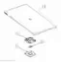
FIG. 1 is an exploded view of the bottom assembly part of the invention.
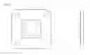
FIG. 1A is a detail view of a sub-plate.
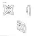
FIG. 1B is a detail view of a bearing assembly.
FIG. IC is a detail view of a base plate.
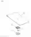
FIG. 2 is an exploded view of the top assembly part of the invention.
FIG. 2A is a detail view of a threaded pin, and of a tee nut.
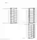
FIG. 3 shows embodiments of the invention's top assembly A-1, and invention's bottom assembly A-2.
DETAILED DESCRIPTION OF THE PREFERRED EMBODIMENT
The present invention is a rotation mechanism consisting of a bottom assembly and a top assembly. The invention is configured for use with a storage cabinet situated in between the bottom and top assembly. FIG. 3 shows embodiments of the invention in a storage unit consisting of an outer stationary casing and an inner rotating storage cabinet. FIG. 3 A-1 showing the invention's top assembly, and FIG. 3 A-2 showing invention's bottom assembly. The invention can be adapted to fit other similar configurations.
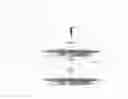
FIG. 1 is an exploded view of the bottom assembly part of the invention. It comprises a double bearing system: a bearing assembly 3, and a bearing 2 housed in sub-plate 1. The double bearing system drastically increases the weight load capacity of the invention. FIG. 1 also illustrates the metallic plate 4 which is screwed into the wooden base of a storage cabinet sitting on top and thereby spinning or rotating the cabinet itself.
FIG. 1A is a detail view of a sub-plate, which is screwed into a stationary housing of the rotating storage. Alternatively, sub-plate is screwed into the floor if the rotating cabinet is a stand-alone unit, that is without stationary housing as shown on FIG. 3.
FIG. 1B is a detail view of a bearing assembly, which consists of a grease fitting and 2 set screws, freely rotating steel flange bearing with center through hole.
FIG. 1C is a detail view of a metallic base plate. The metallic base plate is connected to wood base of the cabinet sitting on top and thereby spinning or rotating the cabinet itself.
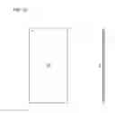
FIG. 2 is an exploded view of the top assembly part of the invention. It consists of an upper stationary panel 8 and a lower rotating panel 5; both panels are aligned and held together by a threaded pin 10, fender washer 9, tee nut 7, and bushing 6.
FIG. 2A is a detail view of a threaded pin, and of a tee nut.
FIG. 3 shows embodiments of the invention's top assembly A-1, and invention's bottom assembly A-2.
As used herein the term “storage” or “cabinet” is defined broadly to encompass any number of storage assemblies, organizers, containing drawers, sections or chambers designed to facilitate orderly grouping of various items.
Claims
What is claimed is:1) A bottom assembly comprising:
a square sub-plate with a housing for a thrust bearing in the center and holes for securing the sub-plate to a cabinet base,
a thrust bearing fitted for a sub-plate,
a bearing assembly,
a plate with a hole in the center and a rod TIG welded to the plate in the center
2) A top assembly comprising:
a static upper panel, part of the outer cabinet casing,
a revolving lower panel, part of the revolving cabinet,
a threaded pin, fender washer, tee nut and a bushing uniting the upper and lower panels.
Images & Drawings included:

Sources:
- United States Patent and Trademark Office - verify current appl. status at the USPTO↗
Recent applications in this class:
- » 20250113917 2025-04-10
Customizable Shower Caddy - » 20240423361 2024-12-26
FURNITURE ELEMENT - » 20240415281 2024-12-19
ROTATING ELEMENT, FURNITURE AND METHOD FOR POSITIONING A TRANSLATIONAL-ROTATIONAL FITTING OF A ROTATING ELEMENT - » 20240335033 2024-10-10
Revolving Storage Cabinet - » 20240315441 2024-09-26
TURNTABLE AND STORAGE CABINET - » 20240306814 2024-09-19
THREE-IN-ONE ROTATABLE KITCHEN SET - » 20220225762 2022-07-21
Customizable shower caddy - » 20210353053 2021-11-18
Customizable shower caddy - » 20210219718 2021-07-22
Support frame - » 20200187641 2020-06-18
Storage shelf base and item of furniture or household appliance