AIRFOIL FOR ROTOR BLADE WITH REDUCED PITCHING MOMENT
US20160122011A1
2016-05-05
14/954,362
2015-11-30
Abstract:
A rotor blade for a rotary wing aircraft includes a root region extending from a rotor head to about 15% to 20% of a blade radius, a main region extending from a radial extent of the root region to about 80% to 95% of the blade radius, a tip region extending from a radial extent of the main region to a blade tip, and a trailing edge. A portion of one of the root region, the main region and the tip region has an airfoil profile section including a trailing edge reflex camber relative to a base airfoil shape of a remainder of the one of the root region, the main region, and the tip region to reduce pitching moment of the rotor blade while maintaining a positive aerodynamic characteristic of the base airfoil shape. The reflex camber extends 20% of a blade chord from the trailing edge.
Interested in similar patents?
Get notified when new applications in this technology area are published.
Classification:
B64C27/463 » CPC further
Rotorcraft; Rotors peculiar thereto; Rotors; Blades Blade tips
B64C27/467 » CPC main
Rotorcraft; Rotors peculiar thereto; Rotors; Blades Aerodynamic features
B64C27/46 IPC
Rotorcraft; Rotors peculiar thereto; Rotors Blades
B64C27/473 » CPC further
Rotorcraft; Rotors peculiar thereto; Rotors; Blades Constructional features
Description
CROSS-REFERENCE TO RELATED APPLICATIONS
This application is a continuation of U.S. application Ser. No. 13/315,767 filed Dec. 9, 2011, the disclosure of which is incorporated by reference herein in its entirety.
BACKGROUND
The subject matter disclosed herein relates to rotary-winged aircraft. More specifically, the subject disclosure relates to an airfoil section for at least partial use on a rotor blade of a helicopter.
Conventional rotary-wing aircraft have a forward airspeed limited by a number of factors. Among these is the tendency of the retreating blade to stall at high forward airspeeds. As the forward airspeed increases, the airflow velocity across the retreating blade slows such that the blade may approach a stall condition. In contrast, the airflow velocity across the advancing blade increases with increasing forward speed producing high lift, but increasingly higher drag that results in higher rotor power requirements. Forward movement of the aircraft thereby generates a dissymmetry of lift between the advancing and retreating sides of the rotor. This dissymmetry may create an unstable condition if lift is not equalized across the advancing and retreating sides of the rotor. An important approach in alleviating this dissymmetry is to use airfoils that are capable of producing high lift at high pitch angles and low relative velocities over the retreating side, while minimizing the increase in drag over the advancing side. However, designing such airfoils results in conflicting requirements as governed by the physics of the problem. That is, designing an airfoil that is capable of producing high lift at low speeds and low drag at high speeds typically results in the manifestation of some other undesirable characteristics, such as pitching moments that exceed the structural-dynamic tolerance of the rotor blades and control hardware.
Many airfoil sections have been developed, for example, as in US Patent Appl. Pub. 2007/0187549, that when applied to a main rotor of a helicopter, alleviate the unstable condition by addressing the lift and drag effects on the blade. These blades, however, exhibit high pitching moments which are detrimental to rotor blade dynamic characteristics.
SUMMARY
Disclosed is a rotor blade for a rotary wing aircraft includes a root region extending from a rotor head to about 15% to 20% of a blade radius, a main region extending from a radial extent of the root region to about 80% to 95% of the blade radius, a tip region extending from a radial extent of the main region to a blade tip, and a trailing edge extending from at least the main region toward the tip region. A portion of one of the root region, the main region and the tip region has an airfoil profile section including a trailing edge reflex camber relative to a base airfoil shape of a remainder of the one of the root region, the main region, and the tip region to reduce pitching moment of the rotor blade while maintaining a positive aerodynamic characteristic of the base airfoil shape. The reflex camber extending 20% of a blade chord from the trailing edge.
These and other advantages and features will become more apparent from the following description taken in conjunction with the drawings.
BRIEF DESCRIPTION OF THE DRAWINGS
The subject matter, which is regarded as the invention, is particularly pointed out and distinctly claimed in the claims at the conclusion of the specification. The foregoing and other features, and advantages of the invention are apparent from the following detailed descriptions taken in conjunction with the accompanying drawings in which:
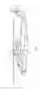
FIG. 1 is a schematic view of an embodiment of a rotary wing aircraft;
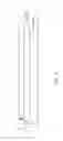
FIG. 2 is a schematic view of an embodiment of a rotor blade of a rotary wing aircraft illustrating root, main and tip areas of the rotor blade; and
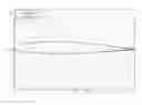
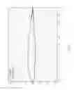
FIG. 3 is a cross-sectional view of an airfoil shape of a rotor blade compared to a prior art airfoil shape.
The detailed description explains embodiments of the invention, together with advantages and features, by way of example with reference to the drawings.
DETAILED DESCRIPTION
Shown in FIG. 1 is a rotary wing aircraft 10 having a main rotor 12 with a plurality of main rotor blades 14. An airframe 16 supports the main rotor 12 and a propulsion system 18 which drives the main rotor 12. The aircraft 10 may also include a tail rotor 20 having a plurality of tail rotor blades 22.
FIG. 2 illustrates a general exemplary plan view of a main rotor blade 14. The main rotor blade 14 includes a root region 24 which extends from a hub 26 over about a first 15% to 20% of a main rotor radius 28 and includes means by which the rotor blade 14 is secured to a rotor head 48. A main region 30 extends from the root region 24 to about 80% to 95% of the radius 28. The blade further includes a tip section 34 that extends outboard of the main section from about 80% to 85% of the radius 28 to the blade tip 36.
The rotor blade 14 has a cross-sectional airfoil shape of the present invention over at least part of the radius 28 which alleviates the pitching moment of prior art blades while maintaining the positive aerodynamic characteristics of the blade 14. This is accomplished by providing a reflex camber over about the aft 20% chord of the blade 14, “aft” referring to a portion of the blade 14 closest to a trailing edge 38 of the blade 14. Reflex camber is imparted on the blade by deflecting the trailing edge 38 upward, in some embodiments by about 6% of chord over the prior art blade. The addition of the reflex camber to the prior art airfoil shape allows such an airfoil shape to be utilized over a larger radius 28 of the blade 14 thereby further maintaining the good lift and low drag aerodynamic characteristics of the airfoil shape but with reduced pitching moment.
Adding reflex camber effectively reduces the net overpressure on the lower surface near the trailing edge thereby reducing the exceedingly large negative (nose-down) pitching moment of the blade 14 that was produced by the original (prior art) airfoil. Reducing the magnitude of the negative pitching moment is a desireable effect and enables the use of the airfoil for rotor-blade applications.
The airfoil cross-sectional shape is shown in FIG. 3 as ratios of x and y coordinates to chord length, “C”. The values are then simultaneously scalable to any dimensional chord length. Because of the difficulty involved on providing an adequate written description of the particular airfoil section being described, the coordinates of a particular embodiment of the current invention reflex airfoil are set forth in Table I below with, as indicated, a first set of coordinates corresponding to an upper surface of the airfoil, as referenced by its attitude during normal upright flight of the helicopter, and a second set of coordinates corresponding to a lower surface of the airfoil.
| TABLE I | ||
| X/C | Y/C | |
| Airfoil Pressure Surface: |
| 1.000000 | 0.008466 | |
| 0.995427 | 0.008495 | |
| 0.989669 | 0.008577 | |
| 0.982521 | 0.008760 | |
| 0.973944 | 0.009084 | |
| 0.964241 | 0.009560 | |
| 0.953842 | 0.010191 | |
| 0.943083 | 0.010961 | |
| 0.932157 | 0.011851 | |
| 0.921155 | 0.012850 | |
| 0.910114 | 0.013947 | |
| 0.899053 | 0.015124 | |
| 0.887980 | 0.016378 | |
| 0.876896 | 0.017700 | |
| 0.865806 | 0.019079 | |
| 0.854709 | 0.020515 | |
| 0.843605 | 0.021997 | |
| 0.832496 | 0.023521 | |
| 0.821380 | 0.025082 | |
| 0.810260 | 0.026673 | |
| 0.799144 | 0.028288 | |
| 0.788035 | 0.029919 | |
| 0.776933 | 0.031560 | |
| 0.765840 | 0.033201 | |
| 0.754752 | 0.034833 | |
| 0.743671 | 0.036445 | |
| 0.732590 | 0.038031 | |
| 0.721512 | 0.039586 | |
| 0.710432 | 0.041099 | |
| 0.699348 | 0.042573 | |
| 0.688261 | 0.044001 | |
| 0.677170 | 0.045382 | |
| 0.666074 | 0.046713 | |
| 0.654975 | 0.047994 | |
| 0.643871 | 0.049224 | |
| 0.632762 | 0.050408 | |
| 0.621651 | 0.051547 | |
| 0.610536 | 0.052641 | |
| 0.599416 | 0.053693 | |
| 0.588295 | 0.054706 | |
| 0.577170 | 0.055679 | |
| 0.566044 | 0.056616 | |
| 0.554916 | 0.057515 | |
| 0.543786 | 0.058378 | |
| 0.532655 | 0.059206 | |
| 0.521522 | 0.059996 | |
| 0.510389 | 0.060750 | |
| 0.499254 | 0.061466 | |
| 0.488117 | 0.062145 | |
| 0.476979 | 0.062786 | |
| 0.465841 | 0.063388 | |
| 0.454702 | 0.063952 | |
| 0.443564 | 0.064477 | |
| 0.432425 | 0.064961 | |
| 0.421287 | 0.065405 | |
| 0.410151 | 0.065808 | |
| 0.399016 | 0.066166 | |
| 0.387884 | 0.066478 | |
| 0.376753 | 0.066743 | |
| 0.365626 | 0.066958 | |
| 0.354501 | 0.067121 | |
| 0.343379 | 0.067232 | |
| 0.332261 | 0.067285 | |
| 0.321146 | 0.067281 | |
| 0.310036 | 0.067213 | |
| 0.298930 | 0.067082 | |
| 0.287829 | 0.066883 | |
| 0.276733 | 0.066616 | |
| 0.265642 | 0.066275 | |
| 0.254557 | 0.065861 | |
| 0.243481 | 0.065366 | |
| 0.232411 | 0.064788 | |
| 0.221351 | 0.064124 | |
| 0.210302 | 0.063371 | |
| 0.199265 | 0.062521 | |
| 0.188242 | 0.061570 | |
| 0.177236 | 0.060512 | |
| 0.166251 | 0.059339 | |
| 0.155291 | 0.058040 | |
| 0.144360 | 0.056604 | |
| 0.133461 | 0.055016 | |
| 0.122600 | 0.053266 | |
| 0.111782 | 0.051336 | |
| 0.101016 | 0.049212 | |
| 0.090317 | 0.046880 | |
| 0.079712 | 0.044325 | |
| 0.069246 | 0.041530 | |
| 0.059004 | 0.038487 | |
| 0.049136 | 0.035199 | |
| 0.039876 | 0.031711 | |
| 0.031535 | 0.028127 | |
| 0.024381 | 0.024597 | |
| 0.018505 | 0.021251 | |
| 0.013799 | 0.018154 | |
| 0.010060 | 0.015297 | |
| 0.007087 | 0.012635 | |
| 0.004724 | 0.010107 | |
| 0.002865 | 0.007662 | |
| 0.001449 | 0.005256 | |
| 0.000468 | 0.002850 |
| Airfoil Suction Surface: |
| 0.000000 | 0.000000 | |
| 0.000262 | −0.001992 | |
| 0.001347 | −0.004210 | |
| 0.003051 | −0.006022 | |
| 0.005216 | −0.007567 | |
| 0.007843 | −0.008982 | |
| 0.011028 | −0.010350 | |
| 0.014933 | −0.011716 | |
| 0.019783 | −0.013104 | |
| 0.025830 | −0.014529 | |
| 0.033254 | −0.015977 | |
| 0.042004 | −0.017398 | |
| 0.051774 | −0.018736 | |
| 0.062178 | −0.019950 | |
| 0.072925 | −0.021036 | |
| 0.083851 | −0.022002 | |
| 0.094871 | −0.022869 | |
| 0.105945 | −0.023649 | |
| 0.117055 | −0.024362 | |
| 0.128187 | −0.025022 | |
| 0.139335 | −0.025639 | |
| 0.150495 | −0.026220 | |
| 0.161666 | −0.026771 | |
| 0.172843 | −0.027305 | |
| 0.184022 | −0.027819 | |
| 0.195203 | −0.028316 | |
| 0.206382 | −0.028797 | |
| 0.217560 | −0.029261 | |
| 0.228734 | −0.029705 | |
| 0.239907 | −0.030125 | |
| 0.251077 | −0.030524 | |
| 0.262243 | −0.030898 | |
| 0.273408 | −0.031244 | |
| 0.284572 | −0.031563 | |
| 0.295735 | −0.031851 | |
| 0.306897 | −0.032111 | |
| 0.318058 | −0.032340 | |
| 0.329219 | −0.032540 | |
| 0.340378 | −0.032709 | |
| 0.351538 | −0.032844 | |
| 0.362698 | −0.032951 | |
| 0.373858 | −0.033026 | |
| 0.385017 | −0.033071 | |
| 0.396176 | −0.033086 | |
| 0.407334 | −0.033067 | |
| 0.418493 | −0.033018 | |
| 0.429652 | −0.032938 | |
| 0.440809 | −0.032829 | |
| 0.451967 | −0.032687 | |
| 0.463125 | −0.032515 | |
| 0.474281 | −0.032311 | |
| 0.485436 | −0.032075 | |
| 0.496592 | −0.031805 | |
| 0.507747 | −0.031502 | |
| 0.518901 | −0.031166 | |
| 0.530056 | −0.030797 | |
| 0.541211 | −0.030394 | |
| 0.552367 | −0.029958 | |
| 0.563524 | −0.029493 | |
| 0.574681 | −0.028995 | |
| 0.585840 | −0.028468 | |
| 0.596999 | −0.027918 | |
| 0.608158 | −0.027339 | |
| 0.619319 | −0.026740 | |
| 0.630479 | −0.026119 | |
| 0.641640 | −0.025477 | |
| 0.652802 | −0.024815 | |
| 0.663965 | −0.024137 | |
| 0.675128 | −0.023444 | |
| 0.686293 | −0.022735 | |
| 0.697458 | −0.022005 | |
| 0.708626 | −0.021257 | |
| 0.719794 | −0.020485 | |
| 0.730964 | −0.019686 | |
| 0.742136 | −0.018862 | |
| 0.753311 | −0.018010 | |
| 0.764486 | −0.017130 | |
| 0.775664 | −0.016218 | |
| 0.786843 | −0.015274 | |
| 0.798023 | −0.014298 | |
| 0.809204 | −0.013293 | |
| 0.820386 | −0.012260 | |
| 0.831565 | −0.011203 | |
| 0.842744 | −0.010126 | |
| 0.853920 | −0.009030 | |
| 0.865090 | −0.007915 | |
| 0.876257 | −0.006789 | |
| 0.887416 | −0.005654 | |
| 0.898563 | −0.004516 | |
| 0.909695 | −0.003387 | |
| 0.920805 | −0.002274 | |
| 0.931874 | −0.001189 | |
| 0.942861 | −0.000144 | |
| 0.953675 | 0.000838 | |
| 0.964125 | 0.001734 | |
| 0.973869 | 0.002511 | |
| 0.982479 | 0.003138 | |
| 0.989650 | 0.003606 | |
| 0.995422 | 0.003942 | |
| 1.000000 | 0.004188 | |
To reduce the pitching moment, in some embodiments, the airfoil shape of Table I is applied at the tip section 34, for example, at an outer 5% to 7% of the blade span 28. It is to be appreciated that the airfoil section of Table I may be applied to other locations along the radius 28, or even the entire radius 28. Further, while in the embodiments described above the airfoil shape is applied to a main rotor blade 14 of a rotary wing aircraft 10, in other embodiments, the airfoil shape described herein may be utilized in, for example, the tail rotor 20 or in other applications such as prop-rotor, propeller blades, turbomachine blades, or the like.
While the invention has been described in detail in connection with only a limited number of embodiments, it should be readily understood that the invention is not limited to such disclosed embodiments. Rather, the invention can be modified to incorporate any number of variations, alterations, substitutions or equivalent arrangements not heretofore described, but which are commensurate with the scope of the invention. Additionally, while various embodiments of the invention have been described, it is to be understood that aspects of the invention may include only some of the described embodiments. Accordingly, the invention is not to be seen as limited by the foregoing description, but is only limited by the scope of the appended claims.
Claims
1. A rotor blade for a rotary wing aircraft comprising:
a root region extending from a rotor head to about 15% to 20% of a blade radius;
a main region extending from a radial extent of the root region to about 80% to 95% of the blade radius;
a tip region extending from a radial extent of the main region to a blade tip; and
a trailing edge extending from at least the main region toward the tip region, wherein a portion of one of the root region, the main region and the tip region has an airfoil profile section including a trailing edge reflex camber relative to a base airfoil shape of a remainder of the one of the root region, the main region, and the tip region to reduce pitching moment of the rotor blade while maintaining a positive aerodynamic characteristic of the base airfoil shape, the reflex camber extending 20% of a blade chord from the trailing edge.
2. The rotor blade according to claim 1, wherein the tip section is defined by an outboard 20% of the rotor blade span.
3. The rotor blade according to claim 2, wherein the airfoil profile section is disposed at least partially at an outermost 5% to 7% of the rotor blade span.
4. The rotor blade according to claim 1, wherein the airfoil profile section is at least partially disposed at the root region.
5. The rotor blade according to claim 1, wherein the rotor blade is a main rotor blade of a helicopter.
6. The rotor blade according to claim 1, wherein the reflex camber extends from the trailing edge upward by a distance of about 6% of the blade chord.
7. The rotor blade according to claim 1, wherein at least a portion of one of the root region, the main region and the tip region including an airfoil profile section defined by a scaled set of coordinates in which a set of x/c coordinates defined as a ratio of an x coordinate to a blade chord length, and y/c coordinates defined as a ratio of a y coordinate to the blade chord length, listed in Table I are scaled by a selected factor.
8. The rotor blade according to claim 7, wherein the tip section is defined by an outboard 20% of the rotor blade span.
9. The rotor blade according to claim 7, wherein the airfoil profile section is at least partially disposed at the root region.
10. The rotor blade according to claim 7, wherein the rotor blade is a main rotor blade of a helicopter.
Images & Drawings included:
Sources:
- United States Patent and Trademark Office - verify current appl. status at the USPTO↗
Similar patent applications:
- » 20130149160
Airfoil for rotor blade with reduced pitching moment
Recent applications in this class:
- » 20250010983 2025-01-09
METHOD OF STABILIZING ARTICULATED ROTOR BLADE - » 20240067333 2024-02-29
Method of stabilizing articulated rotor blade - » 20230322374 2023-10-12
Removable trailing edge assembly and system for rotor blade trailing edge actuation - » 20230322373 2023-10-12
High speed rotor blade design - » 20230303241 2023-09-28
Rotor blade using adaptive trailing edge assembly - » 20230242248 2023-08-03
ROTOR BLADE NOZZLE GENERATING AIR PRESSURE SYSTEM - » 20230122833 2023-04-20
Flight duration enhancement for single rotorcraft and multicopters - » 20220111955 2022-04-14
Method for improving the aerodynamic behavior of rotorcraft blades during hovering flight by moving the leading edge of the aerodynamic profiles of these blades - » 20210371095 2021-12-02
Method for constructing a rotor blade intended for a rotorcraft, blade and rotorcraft - » 20210237862 2021-08-05
ROTARY-WING AIRCRAFT BLADE AIRFOIL, BLADE HAVING THE BLADE AIRFOIL, AND ROTARY-WING AIRCRAFT INCLUDING THE BLADE