Electric brake device
US20160123419A1
2016-05-05
14/894,539
2014-06-06
✅ Patent granted
US 9,732,814 B2
2017-08-15
WO; PCT/JP2014/065068; 20140606
WO; WO2014/199912; 20141218
Melanie Torres Williams
Wenderoth, Lind & Ponack, L.L.P.
2034-06-06
Abstract:
A brake device includes a control device which performs feedback control using a braking force of a linear motion mechanism as a controlled variable. The control device includes a computing unit for computing an operating quantity (voltage applied to an electric motor) for canceling out fluctuations in braking force, and a frequency detector for detecting the frequency of the operating quantity. The control device further includes an operating quantity limiting unit which limits the operating quantity according to a predetermined parameter when the detected frequency is higher than a predetermined frequency threshold, i.e. when the detected frequency is in a high-frequency range in which the permissible value of the braking force fluctuations is high, whereby it is possible to reduce the output of the electric motor within a range in which the braking force fluctuations does not exceed the permissible value, thereby reducing the power consumption.
Assignee:
- NTN Corporation 1,951 🇯🇵 Osaka, Japan
Applicant:
Interested in similar patents?
Get notified when new applications in this technology area are published.
Classification:
B60T13/74 IPC
Transmitting braking action from initiating means to ultimate brake actuator with power assistance or drive; Brake systems incorporating such transmitting means, e.g. air-pressure brake systems with electrical assistance or drive
B60T13/741 » CPC further
Transmitting braking action from initiating means to ultimate brake actuator with power assistance or drive; Brake systems incorporating such transmitting means, e.g. air-pressure brake systems with electrical assistance or drive acting on an ultimate actuator
F16D55/225 » CPC further
Brakes with substantially-radial braking surfaces pressed together in axial direction, e.g. disc brakes with axially-movable discs or pads pressed against axially-located rotating members by clamping an axially-located rotating disc between movable braking members, e.g. movable brake discs or brake pads with a common actuating member for the braking members the braking members being brake pads
F16D2121/24 » CPC further
Type of actuator operation force; Electric or magnetic using motors
F16D65/18 » CPC main
Parts or details; Actuating mechanisms for brakes; Means for initiating operation at a predetermined position arranged in or on the brake adapted for drawing members together, e.g. for disc brakes
F16D2125/40 » CPC further
Components of actuators; Mechanical mechanisms converting rotation to linear movement or acting in the direction of the axis of rotation Screw-and-nut
F16D2125/50 » CPC further
Components of actuators; Mechanical mechanisms transmitting rotation; Rotating members in mutual engagement with parallel non-stationary axes, e.g. planetary gearing
F16D55/226 » CPC further
Brakes with substantially-radial braking surfaces pressed together in axial direction, e.g. disc brakes with axially-movable discs or pads pressed against axially-located rotating members by clamping an axially-located rotating disc between movable braking members, e.g. movable brake discs or brake pads with a common actuating member for the braking members the braking members being brake pads in which the common actuating member is moved axially, e.g. floating caliper disc brakes
F16D65/12 » CPC further
Parts or details; Braking members; Mounting thereof Discs; Drums for disc brakes
Description
TECHNICAL FIELD
The present invention relates to an electric brake device which converts the rotary motion of an electric motor to a linear motion by means of a linear motion mechanism and generates the linear motion as a braking force.
BACKGROUND ART
While old automotive brake devices are mostly hydraulic ones, with an introduction of sophisticated brake control systems such as anti-lock brake control systems (ABS's), electric brake devices, which permit such sophisticated brake control without the need for a complicated hydraulic circuits, are gathering attention these days. Such an electric brake device includes an electric linear motion actuator including a linear motion mechanism for converting the rotary motion of an electric motor to a linear motion of a brake pad, whereby when the electric motor is actuated by e.g. a signal indicative of the depression of the brake pedal, the brake pad is moved linearly and pressed against a brake disk, thereby applying a braking force to the wheel (see, for example, the below-identified Patent documents 1 and 2).
PRIOR ART DOCUMENTS
Patent Documents
Patent document 1: JP Patent Publication 6-327190A
Patent document 2: JP Patent Publication 2006-194356A
SUMMARY OF THE INVENTION
Object of the Invention
In such an electric brake device, since the output of the electric motor is a product of the torque and the number of revolutions, of the motor, the output of the electric motor is zero while the braking force is being maintained. However, while the braking force is changing, the electric motor generates an output in proportion to the number of revolutions of the motor, so that the motor consumes electric power.
Thus, any fluctuations in braking force due to external factors such as electric signal noises, quantizing noises, uneven wear of the brake pads could cause the electric motor to oscillate at high speed, and increase its operating frequency, thereby markedly increasing the power consumption.
Accordingly, an object of the present invention is to reduce the power consumption of such an electric brake device, while reducing fluctuations in braking force of the brake device within a permissible range. Means for Achieving the Object
In order to achieve this object, the present invention provides an electric brake device comprising an electric motor, a linear motion mechanism configured to convert a rotary motion of the electric motor to a linear motion and output the linear motion, and a control device for controlling a braking force generated by the linear motion mechanism, wherein the control device is configured to detect the frequency of one of a control command value, an operating quantity and a controlled variable, and to limit the operating quantity according to a predetermined parameter if the frequency is higher than a predetermined frequency threshold value.
In particular, the inventor of the present application discovered that if the frequency of the braking force fluctuations in the electric brake device is higher than a certain value, the object to be braked is less likely to be affected by the braking force fluctuations, in other words, the permissible range of braking force fluctuations increases. Based on this discovery, according to the present invention, the operating quantity for cancelling out the braking force fluctuations is limited while the frequency of the braking force fluctuations is in the range higher than a frequency threshold value. With this arrangement, it is possible to reduce the output of the electric motor and thus its power consumption, within a range in which the braking force fluctuations are not higher than a permissible value.
If the frequency of the braking force fluctuations is in the range higher than the above-mentioned certain value, the higher this frequency, the higher the permissible braking force fluctuations. Thus, in the above arrangement, the control device is preferably configured to adjust the value of the parameter such that the higher the frequency, the smaller value the operating quantity is limited to, thereby further effectively reducing the power consumption.
If the object to be braked is a wheel of a vehicle, the control device is preferably configured to adjust the value of the parameter based on the relationship between the frequency of the controlled variable and the attenuation factor of acceleration of the vehicle in the fore-and-aft direction of the vehicle, thereby more reliably reduce the influence of the braking force fluctuations on the behavior of the vehicle.
Specific arrangements for limiting the operating quantity include: using, as the parameter, upper and lower limit values of the operating quantity; subtracting the product of a gain as the parameter and the difference between the frequency as detected and the frequency threshold value, from the operating quantity; and providing, as the parameter, a dead band corresponding to a deviation between the control command value and the controlled variable.
Also, the control device may be configured to perform feedback control using the braking force generated by the linear motion mechanism as the controlled variable, and a braking force target value as the control command value, or using, as the controlled variable, one of an electric current applied to the electric motor and the rotational angle of the electric motor, as the control command value, a value obtained by converting the braking force target value based on a predetermined conversion coefficient, and as the operating quantity, a voltage applied to the electric motor.
Advantages of the Invention
As described above, utilizing a phenomenon in which if the frequency of the braking force fluctuations in the electric brake device is higher than a certain value, the object to be braked is less likely to be affected by the braking force fluctuations, in other words, the permissible range of braking force fluctuations increases, the electric brake device according to the present invention is configured such that the operating quantity for cancelling out the braking force fluctuations is limited while the frequency of the braking force fluctuations is high. It is therefore possible to reduce the power consumption, while reducing fluctuations in braking force.
BRIEF DESCRIPTION OF THE DRAWINGS
FIG. 1 shows the entire structure of an electric brake device embodying the present invention.
FIG. 2 is a vertical sectional front view of a mechanical portion of the electric brake device of FIG. 1.
FIG. 3 shows a partial structure of an electric brake device in which a limiter is used as an operating quantity limiting unit of a control device of FIG. 1.
FIGS. 4(a) to 4(c) are graphs showing how the upper limit of the operating quantity according to the frequency of fluctuations in braking force.
FIGS. 5(a) and 5(b) show partial structures of electric brake devices in which different operating quantity limiting arrangemetns are used in the respective control devices in FIG. 2.
BEST MODE FOR EMBODYING THE INVENTION
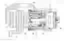
Now the embodiment of the present invention is described with reference to the drawings. FIG. 1 shows the entire electric brake device of the embodiment. This electric brake device includes an electric motor 1, a linear motion mechanism 2 for converting the rotary motion of the electric motor 1 to a linear motion and outputting the linear motion as a braking force, and a control device 3 for controlling the braking force generated by the linear motion mechanism 2.
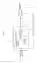
As shown in FIG. 2, the mechanical portion of the electric brake device includes an electric linear motion actuator 11 including the electric motor 1 and the linear motion mechanism 2, and further including a housing, a caliper body 13 integral with the housing 12, a brake disk 14 of which the outer peripheral portion is partially disposed within the caliper body 13, and brake pads 15 and 16 disposed on the respective sides of the brake disk 14.
The electric linear motion actuator 11 includes a gear reduction mechanism 18 through which the rotation of the rotor shaft of the electric motor 1 is transmitted to a rotary shaft 19, and is configured to convert the rotary motion of the rotary shaft 19 to a linear motion of an outer ring member 17 by means of the linear motion mechanism 2. The linear motion mechanism 2 includes a plurality of planetary rollers 20 mounted between the rotary shaft 19 and the outer ring member 17 such that when the rotary shaft 19 rotates, the planetary rollers 20 are rotated about their respective axes while rotating around the rotary shaft 19, due to elastic contact between the planetary rollers 20 and the radially outer surface of the rotary shaft 19, thereby moving the outer ring member 17 in the axial direction due to engagement of a helical rib 17a formed on the radially inner surface of the outer ring member 17 in helical grooves 20a formed in the radially outer surfaces of the respective planetary rollers 20.
In this arrangement, when the electric motor 1 of the electric linear motion actuator 11 is driven to linearly move the outer ring member 17 in the direction toward the brake disk 14 by means of the linear motion mechanism 2, the brake pad 16 and the brake pad 15 clamp the brake disk 14 therebetween, thereby applying a braking force to the vehicle wheel to which the brake disk 14 is mounted.
As shown in FIG. 1, the control device 3 is configured to perform feedback control using the braking force generated by the linear motion mechanism 2 as a controlled variable, and to receive a braking force target value as a control command value, and the controlled variable (braking force feedback value), and includes a computing unit 4 for calculating an operating quantity (voltage to be applied to the electric motor 1) for canceling the deviation between the target value and the feedback value, a frequency detector 5 for detecting the frequency f0 of the operating quantity calculated by the computing unit 4, and an operating quantity limiting unit 6 for limiting the operating quantity based on the frequency detected by the frequency detector 5. The control device 3 applies the operating quantity to the electric motor 1 after being limited by the operating quantity limiting unit 6.
FIG. 3 shows, as the operating quantity limiting unit 6 of the control device 3, a limiter configured to limit the operating quantity within a predetermined range while the frequency f0 of the operating quantity as detected by the frequency detector 5 is higher than a predetermined frequency threshold value fth.
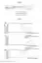
In this limiter (operating quantity limiting unit 6), the upper and lower limit values of the operating quantity, i.e. the parameters that limit the operating quantity are values variable with the frequency f0 of the operating quantity. Now referring to FIGS. 4(a) to 4(c), it is described how the upper limit of the operating quantity is determined. Generally speaking, while a braking force is applied to wheels of a vehicle, the acceleration of the vehicle in its fore-and-aft direction tends to attenuate with an increase in the frequency of the braking force if the frequency is higher than a certain frequency (cut-off frequency), as shown in FIG. 4(a). In particular, within the high frequency range of the braking force, the higher the frequency, the less likely the vehicle behavior is to be influenced by the fluctuations in braking force, and thus larger braking force fluctuations are permissible (as shown in FIG. 4(b)). This makes it possible to limit the operating quantity to a smaller value, and thus to reduce its upper limit value (as shown in FIG. 4(c)).
Therefore, it is preferable to store beforehand permissible values according to the frequencies of the braking force which are determined based on the relationship between the frequency of the braking force and the attenuation factor of the vehicle acceleration in the fore-and-aft direction of the vehicle, and to determine the upper limit of the operating quantity based on the frequency f0 of the operating quantity, which corresponds to the frequency of the braking force such that the braking force fluctuations do not exceed the permissible value, while the frequency f0 is higher than a frequency threshold value fth which is determined based on the frequency characteristics of the acceleration in the fore-and-aft direction. The lower limit of the operating quantity is a negative value identical in absolute value to the upper limit of the operating quantity. With this arrangement, it is possible to limit the operating quantity to a lower value with an increase in the frequency f0.
In order to limit the operating quantity, instead of using the above-described limiter, the control device 3 may be configured as shown in FIGS. 5(a) and 5(b). In the configuration of FIG. 5(a), the control device 3 includes a gain Kf as a parameter for limiting the operating quantity, and is configured to subtract the product of the gain Kf and the difference between the frequency f0 of the operating quantity and the frequency threshold value fth, from the operating quantity. In the configuration of FIG. 5(b), the control device 3 includes, as the parameter for limiting the operating quantity, a dead band corresponding to the deviation between the control command value (control target value) and the controlled variable (braking force feedback value).
If the configuration shown in FIG. 5(a) or 5(b) is used to limit the operating quantity, too, the gain Kf or the dead band, as the parameter for limiting the operating quantity, may be adjusted as a value variable with the frequency f0 of the operating quantity such that the higher the frequency f0, the smaller the operating quantity, as with the upper and lower limit values of the operating quantity in the example of FIG. 3.
Since this electric brake device is configured to limit the operating quantity for canceling the braking force fluctuations according to the predetermined parameter while the frequency f0 of the operating quantity is higher than the frequency threshold value fth corresponding to the cut-off frequency of the acceleration of the vehicle in the fore-and-aft direction, it is possible to reduce the output of the electric motor 1 within the range in which the braking force fluctuations do not exceed the permissible value, i.e. do not affect the vehicle behavior, thereby reducing the power consumption.
The parameter for limiting the operating quantity may be a fixed value, but is preferably a variable value adjustable such that the operating quantity is limited to a smaller value with an increase in frequency, as in the above embodiments, because with this arrangement, it is possible to more effectively reduce the power consumption.
In any of the above embodiments, the frequency detector 5 is configured to detect the frequency f0 of the operating quantity, but may be configured to detect the frequency of the control command value or of the controlled variable.
In the embodiments, the control device 3 is configured to perform feedback control using the braking force generated by the linear motion mechanism 2 as the controlled variable, and the braking force target value as the control command value. However, the control device 3 may be configured to perform feedback control using, as the controlled variable, a state quantity such as the current or rotational angle of the electric motor 1, or the displacement of the movable brake pad 16, and, as the control command value, a value obtained by converting the braking force target value based on a predetermined conversion coefficient so as to correspond to the control variable. Alternatively, feed-forward control may be performed based on the characteristics of the actuator stored beforehand (such as inertia moment, torque or reduction ratio).
The linear motion mechanism 2 may comprise, instead of the planetary roller-screw mechanism used in the embodiments, a ball-screw mechanism or a ball-ramp mechanism.
DESCRIPTION OF THE NUMERALS
- 1. Electric motor
- 2. Linear motion mechanism
- 3. Control device
- 4. Computing unit
- 5. Frequency detector
- 6. Operating quantity limiting unit
- 11. Electric linear motion actuator
- 12. Housing
- 13. Caliper body
- 14. Brake disk
- 15, 16. Brake pad
- 17. Outer ring member
- 18. Gear reduction mechanism
- 19. Rotary shaft
- 20. Planetary roller
Claims
1. An electric brake device comprising an electric motor, a linear motion mechanism configured to convert a rotary motion of the electric motor to a linear motion and output the linear motion, and a control device for controlling a braking force generated by the linear motion mechanism,
wherein the control device is configured to detect a frequency of one of a control command value, an operating quantity and a controlled variable, and to limit the operating quantity according to a predetermined parameter if the frequency is higher than a predetermined frequency threshold value.
2. The electric brake device of claim 1, wherein the control device is configured to adjust a value of the parameter such that the higher the frequency, the smaller value the operating quantity is limited to.
3. The electric brake device of claim 2, wherein the electric brake device is arranged in such a manner that the braking force is applied to a wheel of a vehicle, and wherein the control device is configured to adjust the value of the parameter based on a relationship between the frequency of the controlled variable and an attenuation factor of acceleration of the vehicle in a fore-and-aft direction of the vehicle.
4. The electric brake device of claim 1, wherein the operating quantity is limited by using, as the parameter, upper and lower limit values of the operating quantity.
5. The electric brake device of claim 1, wherein the operating quantity is limited by subtracting a product of a gain as the parameter and a difference between the frequency as detected and the frequency threshold value, from the operating quantity.
6. The electric brake device of claim 1, wherein the operating quantity is limited by providing, as the parameter, a dead band corresponding to a deviation between the control command value and the controlled variable.
7. The electric brake device of claim 1, wherein the control device is configured to perform feedback control using the braking force generated by the linear motion mechanism as the controlled variable, and a braking force target value as the control command value, or using: as the controlled variable, one of an electric current applied to the electric motor and a rotational angle of the electric motor;
as the control command value, a value obtained by converting the braking force target value based on a predetermined conversion coefficient; and as the operating quantity, a voltage applied to the electric motor.
8. The electric brake device of claim 2, wherein the operating quantity is limited by using, as the parameter, upper and lower limit values of the operating quantity.
9. The electric brake device of claim 3, wherein the operating quantity is limited by using, as the parameter, upper and lower limit values of the operating quantity.
10. The electric brake device of claim 2, wherein the operating quantity is limited by subtracting a product of a gain as the parameter and a difference between the frequency as detected and the frequency threshold value, from the operating quantity.
11. The electric brake device of claim 3, wherein the operating quantity is limited by subtracting a product of a gain as the parameter and a difference between the frequency as detected and the frequency threshold value, from the operating quantity.
12. The electric brake device of claim 2, wherein the operating quantity is limited by providing, as the parameter, a dead band corresponding to a deviation between the control command value and the controlled variable.
13. The electric brake device of claim 3, wherein the operating quantity is limited by providing, as the parameter, a dead band corresponding to a deviation between the control command value and the controlled variable.
14. The electric brake device of claim 2, wherein the control device is configured to perform feedback control using the braking force generated by the linear motion mechanism as the controlled variable, and a braking force target value as the control command value, or using: as the controlled variable, one of an electric current applied to the electric motor and a rotational angle of the electric motor; as the control command value, a value obtained by converting the braking force target value based on a predetermined conversion coefficient; and as the operating quantity, a voltage applied to the electric motor.
15. The electric brake device of claim 3, wherein the control device is configured to perform feedback control using the braking force generated by the linear motion mechanism as the controlled variable, and a braking force target value as the control command value, or using: as the controlled variable, one of an electric current applied to the electric motor and a rotational angle of the electric motor; as the control command value, a value obtained by converting the braking force target value based on a predetermined conversion coefficient; and as the operating quantity, a voltage applied to the electric motor.
16. The electric brake device of claim 4, wherein the control device is configured to perform feedback control using the braking force generated by the linear motion mechanism as the controlled variable, and a braking force target value as the control command value, or using: as the controlled variable, one of an electric current applied to the electric motor and a rotational angle of the electric motor; as the control command value, a value obtained by converting the braking force target value based on a predetermined conversion coefficient; and as the operating quantity, a voltage applied to the electric motor.
17. The electric brake device of claim 5, wherein the control device is configured to perform feedback control using the braking force generated by the linear motion mechanism as the controlled variable, and a braking force target value as the control command value, or using: as the controlled variable, one of an electric current applied to the electric motor and a rotational angle of the electric motor; as the control command value, a value obtained by converting the braking force target value based on a predetermined conversion coefficient; and as the operating quantity, a voltage applied to the electric motor.
18. The electric brake device of claim 6, wherein the control device is configured to perform feedback control using the braking force generated by the linear motion mechanism as the controlled variable, and a braking force target value as the control command value, or using: as the controlled variable, one of an electric current applied to the electric motor and a rotational angle of the electric motor; as the control command value, a value obtained by converting the braking force target value based on a predetermined conversion coefficient; and as the operating quantity, a voltage applied to the electric motor.
Images & Drawings included:


Sources:
- United States Patent and Trademark Office - verify current appl. status at the USPTO↗
Similar patent applications:
- » 20170002881
Electric brake device and electric brake device system - » 20210114574
BRAKE DEVICE, ELECTRIC BRAKE DEVICE, AND MOTOR CONTROL DEVICE - » 20210078557
ELECTRIC BRAKE DEVICE AND ELECTRIC BRAKE CONTROL DEVICE - » 20230126047
Electric brake device and electric brake control device - » 20140069750
ELECTRIC BRAKE DEVICE AND METHOD FOR CONTROLLING ELECTRIC BRAKE DEVICE - » 20190145475
Electric brake device and vehicular brake system including electric brake device - » 20090247364
Electric cable drive device and electric brake device - » 20160200294
Electric parking brake driving device and electric parking brake device - » 20060066270
Controller for motor to be mounted on vehicle and electric power steering device and electric brake device using thereof - » 20150233434
Electric parking brake driving device and electric parking brake device
Recent applications in this class:
- » 20250277518 2025-09-04
PISTON FOR DISC BRAKE DEVICE AND DISC BRAKE DEVICE - » 20250271042 2025-08-28
BRAKE ACTUATOR FOR A FRICTION BRAKE, FRICTION BRAKE AND VEHICLE - » 20250271041 2025-08-28
ELECTROMECHANICAL BRAKE - » 20250237279 2025-07-24
ELECTRIC BRAKE DEVICE - » 20250207649 2025-06-26
ELECTROMECHANICALLY ACTUATABLE BRAKE PISTON ASSEMBLY - » 20250207648 2025-06-26
A BRAKE COMPONENT - » 20250207647 2025-06-26
BRAKE ACTUATOR AND BRAKE APPARATUS INCLUDING THE SAME - » 20250207646 2025-06-26
BRAKE ACTUATOR AND BRAKE APPARATUS INCLUDING THE SAME - » 20250198473 2025-06-19
ELECTRO-MECHANICAL BRAKE APPARATUS WITH OFFSET TRANSMISSION SHAFT OF REDUCER, SYSTEM, AND VEHICLE - » 20250189002 2025-06-12
SEAL ASSEMBLY FOR A BRAKE PISTON ASSEMBLY
Recent applications for this Assignee:
- » 20250290543 2025-09-18
TAPERED ROLLER BEARING - » 20250277510 2025-09-04
BALL BEARING - » 20250277507 2025-09-04
TAPERED ROLLER BEARING - » 20250230842 2025-07-17
ROLLING BEARING - » 20250198453 2025-06-19
TAPERED ROLLER BEARING - » 20250188991 2025-06-12
CAGE AND DEEP GROOVE BALL BEARING - » 20250146530 2025-05-08
BALL BEARING - » 20250035153 2025-01-30
BALL BEARING - » 20250027539 2025-01-23
SEALED BEARING - » 20250010467 2025-01-09
CONTROL DEVICE FOR INDUSTRIAL EQUIPMENT