Mop holder
US20160135658A1
2016-05-19
14/920,027
2015-10-22
✅ Patent granted
US 9,801,520 B2
2017-10-31
-
-
Michael Jennings
Myron Greenspan Lackenbach Siegel LLP
2035-10-22
Abstract:
This unit is created to put the mop away and help it dry when is wet. It has three separate pieces. The main unit, which is in the form of a tall rectangular box, contains four equal sides with spaces for ventilation so that the humidity doesn't get trapped in, and a base that will be used to support the unit. The second piece is a snap on piece that will connect with the main unit that helps hold the mop up and be able to stand vertically firm. The third piece is a small drawer where the water will drip from the mop when wet and be emptied out.
Assignee:
- RUBEN DARIO REYES 3 🇺🇸 YONKERS, NY, United States
Applicant:
Interested in similar patents?
Get notified when new applications in this technology area are published.
Classification:
A47L13/50 » CPC main
Implements for cleaning floors, carpets, furniture, walls, or wall coverings; Scrubbing; Scouring; Cleaning; Polishing Auxiliary implements
A47L13/51 » CPC further
Implements for cleaning floors, carpets, furniture, walls, or wall coverings; Scrubbing; Scouring; Cleaning; Polishing; Auxiliary implements Storing of cleaning tools, e.g. containers therefor
A47L13/512 » CPC main
Implements for cleaning floors, carpets, furniture, walls, or wall coverings; Scrubbing; Scouring; Cleaning; Polishing; Auxiliary implements; Storing of cleaning tools, e.g. containers therefor Clamping devices for hanging the tools
Description
These pieces will be built to put the mop away. The “MOP HOLDER” has three separate pieces. The main unit, which is in the form of a tall rectangular box, contains four equal sides with spaces for ventilation so that the humidity doesn't get trapped in, and a base that will be used to support the unit. The second piece is a snap on piece that will connect with the main unit that helps hold the mop up and be able to stand vertically firm. The third piece is a small drawer where the water will drip from the mop when wet and be emptied out.
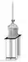
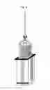
FIG. 1: “Mop Holder” shows the complete body of this unit with all its pieces and a demonstration of what the final outcome will be like.
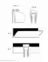
FIG. 2a shows the back side of the hook that will be used to place the mop inside the main unit.
FIG. 2b: shows the front side of the hook where the mop pole will be placed and snap on with pressure to remain sturdy and for easy use
FIG. 3: shows the fixed piece that comes within the main unit to hold the hook
FIG. 4: shows the fixed piece from FIG. 3 with the hook piece from FIGS. 2a and 2b when they are assembled together
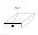
FIG. 5: shows the bottom piece or drawer that will hold any water if the mop is dripping, one can easily remove it from the main unit to empty it out and put it back in
FIG. 6 shows a demonstration with the mop snapped in the hook piece and how it will go inside the main unit or can be pulled out
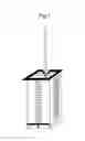
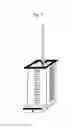
FIG. 7: shows a final result of how the mop will be and how the drawer is place at the bottom and can slide open to remove any water and can slide back in
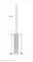
FIG. 8: is showing the back side of the main unit with a mop placed inside the body
Claims
I claim that:1. The “Mop Holder” will consist of three separate pieces. The main unit, which is in the form of a tall rectangular box, contains four equal sides with spaces for ventilation so that the humidity doesn't get trapped in, and a base that will be used to support the unit. The second piece is a snap on piece that will connect with the main unit that helps hold the mop up and be able to stand vertically firm. The third piece is a small drawer where the water will drip from the mop when wet and be emptied out. For use, a person would simply grasp the mop handle and then slide the end of the mop into the space incorporated into the top of the “Mop Holder”. This specially designed holder would allow the mop to stand vertically to help the mop dry. It is easy to snap on. It would provide consumers with a safe, compact, easy-to-access, and aesthetically-appealing means of storing and drying a mop.
(a) The “Mop Holder” could be produced from plastic or wood, as well as other various materials.
(b) It could also be produced in a variety of colors and easily use conventional and readily available materials and manufacturing processes. No new production technology would be required. It could be produced from a plastic such as polystyrene. This material, which is readily available in color, is reasonably priced and easily formed by a wide range of plastic processors. Injection molding might be viewed as a standard approach to production.
(c) Alternatively, the “Mop Holder” could be produced from wood, oak, poplar using conventional manufacturing processes. Currently, many manufacturers use Computer Numerical Controlled saws, shapers, routers, lathes, drills, etc., to produce consistent wood shapes and parts. A manufacturer may use conveyers and other material handling machinery to lift, position, or feed the stock into the woodworking equipment as well as to handle the outfeed. Production worker will control the operation of any equipment and would complete any other aspects of the fabrication process manually.
(d) The “Mop Holder” could be packaged in a cardboard pressboard box, sized to the product. The box could be imprinted in one or more colors. A small pamphlet could be included in each package detailing instructions for assembly or installation. Corrugated cardboard shipping containers would be used to hold a quantity of individually packaged products to facilitate shipment and storage.
Images & Drawings included:
Sources:
- United States Patent and Trademark Office - verify current appl. status at the USPTO↗
Similar patent applications:
- » 20240382060
FLAT MOP COVER, FLAT MOP HOLDER, MOP SYSTEM, METHOD FOR PRODUCING A FLAT MOP COVER, KIT OF PARTS, AND USE OF A FLAT MOP COVER - » 20240389825
MOP HOLDER FOR A MOP SYSTEM, MOP SYSTEM, MOP HANDLE FOR A MOP SYSTEM, AND USE OF THE MOP SYSTEM - » 20170280962
Replaceable scrubbing device attachable to a mop holder - » 20220125272
MOP HOLDER - » 20250134340
MOP HOLDER, CONNECTING PIECE, KIT OF PARTS, AND USE THEREOF - » 20100175211
Mop holder - » 20230032482
Upright Mop Holder - » 20100175210
Screw type mop holder - » 20140059791
CLEANING MEMBER MOUNTING HOLDER FOR MOP AND MOP - » 20090151100
Mop swab holder
Recent applications in this class:
- » 20250204743 2025-06-26
MOP WASHING APPARATUS AND MOP WASHING SYSTEM COMPRISING SAME - » 20250143531 2025-05-08
MOP BUCKET WITH CLEAN AND DIRTY WATER SEPARATION - » 20250098929 2025-03-27
Blade Mop - » 20240415361 2024-12-19
MOP CLEANING APPARATUS - » 20240398198 2024-12-05
Cleaning Wipe Tool and Method of Using Same - » 20240398197 2024-12-05
SCRAPER STRUCTURE, AND CLEANING BUCKET AND HAND WASH-FREE MOP WITH SAME - » 20240164616 2024-05-23
METHOD FOR ELECTRONICALLY DOCUMENTING A CLEANING PROCESS - » 20240115106 2024-04-11
MOP ASSEMBLY WITH SLIDING, ROTATABLE AND CLAMPING WRINGER SLEEVE - » 20220330783 2022-10-20
Device for releasing and detaching a floor cleaning cloth from the support base retaining it - » 20220125272 2022-04-28
MOP HOLDER
Recent applications for this Assignee:
- » 20160249735 2016-09-01
Broom holder - » 20160135653 2016-05-19
Clean lift