Device for forming metals
US20160144416A1
2016-05-26
15/010,458
2016-01-29
✅ Patent granted
US 9,687,899 B2
2017-06-27
-
-
David B Jones
Taylor IP, P.C.
2036-01-29
Abstract:
The invention relates to a device for processing a workpiece, said device including the following features: a punch on one side of the workpiece, a die on the opposite side of the workpiece, and a conductive electric heating system for generating an electric current that flows through the workpiece starting from a component situated on one side of the workpiece outside of the punch to a component situated on the opposite side of the workpiece outside of the die.
Inventors:
- Michael Wolf 3 🇩🇪 Uhingen, Germany
- Ottmar Lehr 3 🇩🇪 Rechberghausen, Germany
- Matthias Mihm 1 🇩🇪 Stuttgart, Germany
- Alexander Müller 1 🇩🇪 Stuttgart, Germany
Assignee:
- Allgaier Werke GmbH 8 🇩🇪 Uhingen, Germany
Applicant:
Interested in similar patents?
Get notified when new applications in this technology area are published.
Classification:
B21D22/022 » CPC main
Shaping without cutting, by stamping, spinning, or deep-drawing; Stamping using rigid devices or tools by heating the blank or stamping associated with heat treatment
B21D22/02 IPC
Shaping without cutting, by stamping, spinning, or deep-drawing Stamping using rigid devices or tools
B21D19/088 » CPC further
Flanging or other edge treatment, e.g. of tubes by single or successive action of pressing tools, e.g. vice jaws for flanging holes
B21D31/005 » CPC further
Other methods for working sheet metal, metal tubes, metal profiles Incremental shaping or bending, e.g. stepwise moving a shaping tool along the surface of the workpiece
B21D22/04 » CPC further
Shaping without cutting, by stamping, spinning, or deep-drawing; Stamping using rigid devices or tools for dimpling
B21D5/00 IPC
Bending sheet metal along straight lines, e.g. to form simple curves
B21D5/008 » CPC further
Bending sheet metal along straight lines, e.g. to form simple curves combined with heating or cooling of the bends
B21D26/02 » CPC further
Shaping without cutting otherwise than using rigid devices or tools or yieldable or resilient pads, i.e. applying fluid pressure or magnetic forces by applying fluid pressure
B21D37/16 » CPC further
Tools as parts of machines covered by this subclass Heating or cooling
B21D41/04 » CPC further
Application of procedures in order to alter the diameter of tube ends Reducing; Closing
B21D5/04 » CPC further
Bending sheet metal along straight lines, e.g. to form simple curves on brakes making use of clamping means on one side of the work
B21D19/08 IPC
Flanging or other edge treatment, e.g. of tubes by single or successive action of pressing tools, e.g. vice jaws
B21D22/00 » CPC further
Stamping, Spinning, Deep-drawing; Working sheet metal of limited length by stretching; Punching
B21D22/00 » CPC further
Shaping without cutting, by stamping, spinning, or deep-drawing
B21D31/00 IPC
Other methods for working sheet metal, metal tubes, metal profiles
Description
CROSS REFERENCE TO RELATED APPLICATIONS
This is a continuation of PCT application No. PCT/EP2014/065822, entitled “DEVICE FOR FORMING METALS”, filed Jul. 23, 2015, which is incorporated herein by reference.
BACKGROUND OF THE INVENTION
1. Field of the Invention
The invention relates to a device for forming metals, in particular forming of parts, such as the forming of a collar.
2. Description of the Related Art
The forming of a collar on a workpiece made of steel, for example a steel sheet plate made of the material of the plate, is an important topic. See DE 10 2006 029 124 B4 as well as DE 1 916 826, for example. The workpiece is placed on a die. The die includes a bore, which is adjacent to the workpiece. A hole is then pressed into the workpiece by means of a tipped punch while material is drawn into the die bore out of the sheet metal plane. As a result, a collar is formed which remains part of the workpiece. The above principle is particularly used in the automobile industry.
The described forming process involves stress to the workpiece within the forming zone. As such, mainly tensile stress take effect when raising the collar in the sheet metal edge. The reachable collar height is limited. The smaller the ratio between collar diameter to collar height, the higher is the risk of a breaking of the material in the collar region.
Forming failures are a big problem. Occasionally, this is not recognized before using the workpiece. Disassembly of defective parts and replacement with flawless parts is particularly complex in such a case.
It has already been attempted to optimize the drawing process by application of heat. For example, the punch can be heated in order to apply heat to the forming zone of the workpiece, e.g. the sheet metal plate. However, this provides the disadvantage that the punch loses its strength because it is heated and thus only has a short service life.
JP-A-2009262184 discloses a device which uses heat. By way of said device, a pot-type object is heated prior to a forming process. To that end, electrodes need to be advanced to the workpiece and then removed again in order to make room for advancing a tappet together with a punch. Processing is thus divided into two stages, which implies time effort.
JP-A-2007260761 describes a device which includes two electrodes for heating a steel sheet. When heating said sheet, first a tappet needs to be lifted and then lowered again after heating. This also requires time.
SUMMARY OF THE INVENTION
The present invention provides a device for forming a collar on a workpiece made of sheet metal, particularly on a sheet metal plate or the like, by way of which the forming process is improved and the risk of a break of the collar is reduced but at the same time the tool elements involved keep their strength. In particular, the device includes few components and performs the processing steps more rapidly than known devices.
The inventors have recognized that they need to search for a solution that involves heating the forming region of the workpiece, however not the tool, particularly the punch. Thus, one had to search for a system according to the principle of “hot workpiece, cold tool”.
The solution according to the present invention lies with the following:
-
- A sleeve is provided, which surrounds the punch and which consists of electrically well-conducting material.
- A counterholder insertable into the die bore is provided, which is made of a material that is also a good electric conductor.
- The counterholder can be displaced downward corresponding to the downward movement of the punch.
- The sleeve serves as a blank holder and simultaneously as an electrode.
In such a device, heating the punch is not effected, since the current is not guided through the punch but through the sleeve and the counterholder.
The present invention solves the underlying object in an advantageous manner:
-
- essentially only the workpiece is heated, also only in the forming region, thus focused on a narrow region. In contrast, the tool essentially remains cold.
- pre-cut parts and formed parts of high-strength thin sheet metal may be used, since the break risk when forming (drawing) the collar is reduced in the invention. This saves weight and costs as well.
BRIEF DESCRIPTION OF THE DRAWINGS
The above-mentioned and other features and advantages of this invention, and the manner of attaining them, will become more apparent and the invention will be better understood by reference to the following description of embodiments of the invention taken in conjunction with the accompanying drawings, wherein:
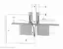
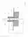
FIG. 1 shows a device according to the invention with a punch, a die and a workpiece, a sleeve surrounding the punch, and a counterholder in the die;
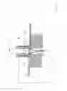
FIG. 2 shows an alternate embodiment of the device of FIG. 1;
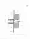
FIG. 3 shows another alternate embodiment of the device of FIG. 1; and
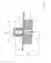
FIG. 4 illustrates the embodiments of FIGS. 2 and 3 after forming the collar.
Corresponding reference characters indicate corresponding parts throughout the several views. The exemplifications set out herein illustrates embodiments of the invention, and such exemplifications are not to be construed as limiting the scope of the invention in any manner.
DETAILED DESCRIPTION OF THE INVENTION
Referring now to FIG. 1, the illustrated device includes a punch 1 as well as a die 2. Further included is a conductive electric heating system with a power supply 3. Punch 1 is surrounded by a sleeve-shaped blank holder 5. A sheet metal plate 4 made of high-strength steel is placed on the die 2.
The punch 1 consists of a high-strength material. The punch 1 includes a tip 1.1. Said tip penetrates a bore 4.1 in the sheet metal plate 4. The bore may have been formed in the sheet metal plate 4 prior to the forming process. However, it is also possible for the sheet metal plate 4 to not have a bore, so that only the punch 1 forms the bore when impressing the sheet metal plate 4. The punch 1 may also be blunt. The shape of the front punch end may also be adapted to the requirements of the forming process. Punch 1 is surrounded by a blank holder 5.
As illustrated, there is a current flow 3.1, starting from the electric power source 3 through the electrically well-conductive blank holder 5, further through a certain forming region of the sheet metal plate 4 and then to a counterholder 6 which consists of an electrically well-conducting material such as copper.
In the illustration according to FIG. 1, the forming process is in an initial stage. Upon completion of the forming process, the bore 4.1 is widened in order to have the shape of the desired collar—not shown here. Then, the collar has an interior width that is equal to the diameter of the punch 1. This can be seen in FIG. 4.
Blank holder 5 has three functions at once. On the one side, it serves as a blank holder, on the other side as a current conductor, and finally as a stripper.
Punch 1 is completely free of current flow and is thus not actively heated. Thus it may be a tool steel of common quality, or hot-work steel. An air gap may be present between the punch 1 and the blank holder 5. However, this is not obligatory.
There is no need for the blank holder 5 to have a great strength. It may be made of copper. In any case, it should consist of an electrically well-conducting material. The same applies to the counterholder 6.
In this case, the material of the die 2 is insignificant. It may be any material—steel or copper, preferably however a less heat-conducting material so that the heat generated by the current remains restricted to the actual forming region.
The alternate embodiment of FIG. 2 again shows the punch 1, die 2, and sheet metal plate 4. Here, illustration and effect of an electric heating system are not discussed. Nevertheless, such a heating system is present. The significant component in FIG. 2 is an insulating coating 7. Said insulating coating 7 may be a sleeve or a coat.
The forming process is performed as follows: first, the sheet metal plate 4 is placed on the die 2. The blank holder 5 moves down and rests on the sheet metal plate 4 so that a current flow is activated and the forming zone is heated. Then, the punch 1 moves farther down and the blank holder 5 springs inward. Just before the punch touches the sheet metal plate 4, the power is switched off and the counterholder 6 is controlled away. The collar is raised while being formed.
The significant component in the alternate embodiment according to FIG. 3 is a thread molder 1.2 on the punch 1. Punch 1 is equipped with a schematically shown rotary drive. As it travels downward, punch 1 and thus the thread molder 1.2 are put in rotation. As a result, the developing collar (not shown) is formed with a thread through which a screw may be guided.
As shown in FIG. 4, one may discern the collar 4.2 for the first time—being formed integrally with the remaining sheet metal plate 4. As illustrated, a thread molder 1.2 may again be discerned as in the embodiment according to FIG. 3, and an insulating coating 7 as in the embodiment according to FIG. 2.
If the forming capability of an existing collar for forming the thread is not sufficient, said collar may also actively be heated. For all embodiments described, either direct current (DC) or a low-frequency alternating current (AC) may be used for heating.
In all illustrations, individual elements of the device may be replaced by one another, e.g. the punch 1 and the die 2. The working direction of the punch is not limited to the vertical.
The basic idea underlying the invention is that exclusively or predominantly the workpiece is heated. In contrast, the tool is not heated, or heated only to a minor extent, so that its strength is reduced only insignificantly.
While this invention has been described with respect to at least one embodiment, the present invention can be further modified within the spirit and scope of this disclosure. This application is therefore intended to cover any variations, uses, or adaptations of the invention using its general principles. Further, this application is intended to cover such departures from the present disclosure as come within known or customary practice in the art to which this invention pertains and which fall within the limits of the appended claims.
REFERENCE NUMERAL LIST
- 1. punch
- 1.1 punch tip
- 1.2 thread molder
- 2. die
- 2.1 die bore
- 3 power source
- 3.1 current flow
- 4 sheet metal plate
- 4.1 bore
- 4.2 collar
- 5 blank holder
- 6 counterholder
- 7 insulating coating
Claims
What is claimed is:1. A device for processing a workpiece, the device comprising:
a punch on one side of the workpiece;
a die on a side of the workpiece opposite the punch;
a first component situated on one side of the workpiece outside of the punch, the first component a sleeve made of an electrically well-conducting material surrounding the punch and operable to be placed on the workpiece, the sleeve serving as a blank holder and at the same time as an electrode;
a second component situated within the die on an opposite side of the workpiece, the second component a counterholder made of an electrically well-conducting material insertable into a bore of the die, the counterholder operable to be displaced downward corresponding to the downward movement of the punch; and
a conductive electric heating system for generating an electric current which flows one of completely and predominantly through the workpiece, starting from the first component to the second component.
2. The device according to claim 1, wherein an inner face of the bore of the die is lined with at least one of an electrically insulating material and a heat insulating material.
3. The device according to claim 1, wherein an inner face of the sleeve is lined with at least one of an electrically insulating material and a heat insulating material.
4. The device according to claim 3, wherein the punch can be driven around its longitudinal axis and includes a thread molder for forming a thread in an inner face of the collar.
Images & Drawings included:
Sources:
- United States Patent and Trademark Office - verify current appl. status at the USPTO↗
Similar patent applications:
- » 10772215
Metal forming device including bearing with sintered anti-friction bearing surface - » 20200398328
Production method for pressed components, press forming device, and metal sheet for press forming - » 20210114076
Production method for pressed components, press forming device, and metal sheet for press forming - » 9648750
Metal interconnection, semiconductor device, method for forming metal interconnection and method for fabricating semiconductor device - » 10687412
Hydraulic forming process, hydraulic forming device and metal separator for a fuel cell formed by hydraulic forming process - » 20240266291
MATERIAL FOR METAL LINE, METAL LINE IN SEMICONDUCTOR DEVICE AND METHOD FOR FORMING METAL LINE IN SEMICONDUCTOR DEVICE - » 20240194604
MATERIAL FOR METAL LINE IN SEMICONDUCTOR DEVICE, METAL LINE IN SEMICONDUCTOR DEVICE, AND METHOD FOR FORMING METAL LINE IN SEMICONDUCTOR DEVICE - » 20100027122
Metal Mold, Optical Device, Metal Mold for Forming Optical Device, and Process for Manufacturing the Same - » 20150021775
Method for manufacturing semiconductor device for forming metal element-containing layer on insulating layer in which concave portion is formed, semiconductor device including insulating layer in which concave portion is formed, and semiconductor layer on insulating layer in which concave portion is formed - » 20080211039
Nonvolatile memory devices having metal silicide nanocrystals, methods of forming metal silicide nanocrystals, and methods of forming nonvolatile memory devices having metal silicide nanocrystals
Recent applications in this class:
- » 20250222506 2025-07-10
CRACK-CONTAINING HOT-STAMPED COATED STEEL PART WITH EXCELLENT SPOT-WELDABILITY AND EXCELLENT PAINTING ADHESION - » 20250222505 2025-07-10
PRODUCTION METHOD AND DIE FOR HOT STAMPED MEMBER COMPRISING LOCAL SOFT REGION, AND HOT STAMPED MEMBER - » 20250196213 2025-06-19
HOT STAMPING METHOD FOR PRE-COATED STEEL SHEETS - » 20250178059 2025-06-05
MOLDED COMPONENT AND METHOD FOR PRODUCING A MOLDED COMPONENT - » 20250153234 2025-05-15
HOT PRESS-FORMED PART AND MANUFACTURING METHOD THEREOF - » 20250144692 2025-05-08
METHOD AND FIXTURE FOR LOCAL SOFTENING OF HOT STAMPED MEMBER - » 20250144691 2025-05-08
MULTI-SENSOR-BASED HOT FORMING PRODUCTION SYSTEM FOR ALUMINUM ALLOY SHEET METAL PART AND CONTROL METHOD THEREOF - » 20250121423 2025-04-17
PRESS SYSTEM AND METHOD OF MANUFACTURING HOT STAMPED STRUCTURAL COMPONENT - » 20250114837 2025-04-10
CRACK-CONTAINING HOT-STAMPED COATED STEEL PART WITH EXCELLENT SPOT-WELDABILITY AND EXCELLENT PAINTING ADHESION - » 20250108424 2025-04-03
HOT-STAMPING FORMED BODY
Recent applications for this Assignee:
- » 20220048041 2022-02-17
System and method for the gravimetric sorting of a mixture of substances - » 20200188957 2020-06-18
Device and method for capturing movement patterns of tumbler screening machines - » 20190186835 2019-06-20
Rotary cooler and method for operating a rotary cooler - » 20190126322 2019-05-02
Screening machine - » 20140352390 2014-12-04
Device and method for machining a workpiece consisting of metal, particularly for producing a cup-shaped component for the automobile industry, as well as such a workpiece - » 20120211032 2012-08-23
Method and device for preparing broken glass - » 20110083485 2011-04-14
Roll forming method for producing longitudinally toothed profiled bodies in pot-shaped cylindrical workpieces