High-modulus coating for local stiffening of airfoil trailing edges
US20160146022A1
2016-05-26
14/903,856
2014-07-09
✅ Patent granted
US 10,227,704 B2
2019-03-12
WO; PCT/US2014/045929; 20140709
WO; WO2015/053832; 20150416
Richard G Davis
Cantor Colburn LLP
2035-04-16
Abstract:
An airfoil is disclosed. The airfoil may comprise a leading edge, a body portion and a trailing edge formed from a high-modulus plating. The body portion of the airfoil may be formed from a material having a lower elastic modulus than the high-modulus plating. The high-modulus plating may improve the stiffness of the trailing edge, allowing for thinner trailing edges with improved fatigue life to be formed.
Inventors:
- Wendell V. Twelves 43 🇺🇸 Glastonbury, CT, United States
- Grant O. Cook, III 74 🇺🇸 Spring, TX, United States
- Grant O. Cook 22 🇺🇸 Spring, TX, United States
Assignee:
- UNITED TECHNOLOGIES CORPORATION 3,722 🇺🇸 Farmington, CT, United States
Applicant:
Interested in similar patents?
Get notified when new applications in this technology area are published.
Classification:
B64C39/02 IPC
Aircraft not otherwise provided for characterised by special use
B64C39/024 » CPC further
Aircraft not otherwise provided for characterised by special use of the remote controlled vehicle type, i.e. RPV
B64C39/028 » CPC further
Aircraft not otherwise provided for characterised by special use Micro-sized aircraft
F01D5/288 » CPC main
Blades; Blade-carrying members ; Heating, heat-insulating, cooling or antivibration means on the blades or the members; Blades; Selecting particular materials; Particular measures relating thereto; Measures against erosion or corrosion Protective coatings for blades
F01D9/041 » CPC further
Stators; Nozzles; Nozzle boxes; Stator blades; Guide conduits, e.g. individual nozzles forming ring or sector using blades
B64C2201/10 » CPC further
Unmanned aerial vehicles; Equipment therefor characterised by the lift producing means
F05D2220/32 » CPC further
Application in turbines in gas turbines
F05D2230/312 » CPC further
Manufacture with deposition of material; Layer deposition by plasma spraying
F05D2240/122 » CPC further
Components; Stators; Fluid guiding means, e.g. vanes related to the trailing edge of a stator vane
F05D2240/304 » CPC further
Components; Rotors; Characteristics of rotor blades, i.e. of any element transforming dynamic fluid energy to or from rotational energy and being attached to a rotor related to the trailing edge of a rotor blade
F01D5/28 IPC
Blades; Blade-carrying members ; Heating, heat-insulating, cooling or antivibration means on the blades or the members; Blades Selecting particular materials; Particular measures relating thereto; Measures against erosion or corrosion
F05D2300/121 » CPC further
Materials; Properties thereof; Metals, alloys or intermetallic compounds; Light metals Aluminium
F05D2300/133 » CPC further
Materials; Properties thereof; Metals, alloys or intermetallic compounds; Refractory metals, i.e. Ti, V, Cr, Zr, Nb, Mo, Hf, Ta, W Titanium
F05D2300/171 » CPC further
Materials; Properties thereof; Metals, alloys or intermetallic compounds; Alloys Steel alloys
F05D2300/177 » CPC further
Materials; Properties thereof; Metals, alloys or intermetallic compounds; Alloys Ni - Si alloys
F05D2300/20 » CPC further
Materials; Properties thereof Oxide or non-oxide ceramics
F05D2300/44 » CPC further
Materials; Properties thereof; Organic materials Resins
B62D35/00 » CPC further
Vehicle bodies characterised by streamlining
F01D9/04 IPC
Stators; Nozzles; Nozzle boxes; Stator blades; Guide conduits, e.g. individual nozzles forming ring or sector
F42B10/02 » CPC further
Means for influencing, e.g. improving, the aerodynamic properties of projectiles or missiles; Arrangements on projectiles or missiles for stabilising, steering, range-reducing, range-increasing or fall-retarding Stabilising arrangements
B05D7/02 » CPC further
Processes, other than flocking, specially adapted for applying liquids or other fluent materials to particular surfaces or for applying particular liquids or other fluent materials to macromolecular substances, e.g. rubber
C04B35/80 IPC
Shaped ceramic products characterised by their composition ; Ceramics compositions ; Processing powders of inorganic compounds preparatory to the manufacturing of ceramic products; Ceramic products containing macroscopic reinforcing agents containing non-metallic materials Fibres, filaments, whiskers, platelets, or the like
B22C7/023 » CPC further
Patterns; Manufacture thereof so far as not provided for in other classes; Lost patterns Patterns made from expanded plastic materials
B22F3/225 » CPC further
Manufacture of workpieces or articles from metallic powder characterised by the manner of compacting or sintering; Apparatus specially adapted therefor ; Presses and furnaces for producing castings from a slip by injection molding
B28B7/34 IPC
Moulds; Cores; Mandrels Moulds, cores, or mandrels of special material, e.g. destructible materials
B28B7/342 » CPC further
Moulds; Cores; Mandrels; Moulds, cores, or mandrels of special material, e.g. destructible materials which are at least partially destroyed, e.g. broken, molten, before demoulding; Moulding surfaces or spaces shaped by, or in, the ground, or sand or soil, whether bound or not; Cores consisting at least mainly of sand or soil, whether bound or not
B28B11/243 » CPC further
Apparatus or processes for treating or working the shaped or preshaped articles for curing, setting or hardening Setting, e.g. drying, dehydrating or firing ceramic articles
B32B15/20 » CPC further
Layered products comprising a layer of metal comprising aluminium or copper
B32B37/12 » CPC further
Methods or apparatus for laminating, e.g. by curing or by ultrasonic bonding characterised by using adhesives
B32B37/14 » CPC further
Methods or apparatus for laminating, e.g. by curing or by ultrasonic bonding characterised by the properties of the layers
B32B37/1284 » CPC further
Methods or apparatus for laminating, e.g. by curing or by ultrasonic bonding characterised by using adhesives Application of adhesive
C04B35/76 » CPC further
Shaped ceramic products characterised by their composition ; Ceramics compositions ; Processing powders of inorganic compounds preparatory to the manufacturing of ceramic products; Ceramic products containing macroscopic reinforcing agents containing shaped metallic materials Fibres, filaments, whiskers, platelets, or the like
B05D5/00 » CPC further
Processes for applying liquids or other fluent materials to surfaces to obtain special surface effects, finishes or structures
C23C16/06 » CPC further
Chemical coating by decomposition of gaseous compounds, without leaving reaction products of surface material in the coating, i.e. chemical vapour deposition [CVD] processes characterised by the deposition of metallic material
C23C18/16 IPC
Chemical coating by decomposition of either liquid compounds or solutions of the coating forming compounds, without leaving reaction products of surface material in the coating; Contact plating by reduction or substitution, e.g. electroless plating
C23C18/165 » CPC further
Chemical coating by decomposition of either liquid compounds or solutions of the coating forming compounds, without leaving reaction products of surface material in the coating; Contact plating by reduction or substitution, e.g. electroless plating; Process or apparatus; Process of electroless plating; Characteristics of the product obtained Multilayered product
C23C26/00 » CPC further
Coating not provided for in groups -
C23C28/02 » CPC further
Coating for obtaining at least two superposed coatings either by methods not provided for in a single one of groups - or by combinations of methods provided for in subclasses and or only coatings only including layers of metallic material
C25D3/02 » CPC further
Electroplating: Baths therefor from solutions
C25D3/38 » CPC further
Electroplating: Baths therefor from solutions of copper
C25D3/46 » CPC further
Electroplating: Baths therefor from solutions of silver
C25D5/48 » CPC further
Electroplating characterised by the process; Pretreatment or after-treatment of workpieces After-treatment of electroplated surfaces
C25D9/04 » CPC further
Electrolytic coating other than with metals with inorganic materials
C25D11/20 » CPC further
Electrolytic coating by surface reaction, i.e. forming conversion layers; Anodisation of aluminium or alloys based thereon; After-treatment, e.g. pore-sealing Electrolytic after-treatment
F01D5/00 » CPC further
Blades; Blade-carrying members ; Heating, heat-insulating, cooling or antivibration means on the blades or the members
F01D5/14 IPC
Blades; Blade-carrying members ; Heating, heat-insulating, cooling or antivibration means on the blades or the members; Blades Form or construction
F01D5/147 » CPC further
Blades; Blade-carrying members ; Heating, heat-insulating, cooling or antivibration means on the blades or the members; Blades; Form or construction Construction, i.e. structural features, e.g. of weight-saving hollow blades
F01D25/00 IPC
Component parts, details, or accessories, not provided for in, or of interest apart from, other groups
F05D2230/22 » CPC further
Manufacture essentially without removing material by sintering
B33Y80/00 » CPC further
Products made by additive manufacturing
B22C9/043 » CPC further
Moulds or cores ; Moulding processes; Sand moulds or like moulds for shaped castings; Use of lost patterns Removing the consumable pattern
B22F3/22 IPC
Manufacture of workpieces or articles from metallic powder characterised by the manner of compacting or sintering; Apparatus specially adapted therefor ; Presses and furnaces for producing castings from a slip
B28B1/24 » CPC further
Producing shaped prefabricated articles from the material by injection moulding
B28B11/24 IPC
Apparatus or processes for treating or working the shaped or preshaped articles for curing, setting or hardening
B32B3/263 » CPC further
Layered products comprising a layer with external or internal discontinuities or unevennesses, or a layer of non-planar form ; Layered products having particular features of form characterised by a particular shape of the outline of the cross-section of a continuous layer; characterised by a layer with cavities or internal voids ; characterised by an apertured layer characterised by a layer having non-uniform thickness
C23C14/20 » CPC further
Coating by vacuum evaporation, by sputtering or by ion implantation of the coating forming material characterised by the coating material; Metallic material, boron or silicon on organic substrates
C23C18/1633 » CPC further
Chemical coating by decomposition of either liquid compounds or solutions of the coating forming compounds, without leaving reaction products of surface material in the coating; Contact plating by reduction or substitution, e.g. electroless plating; Process or apparatus Process of electroless plating
C23C18/2013 » CPC further
Chemical coating by decomposition of either liquid compounds or solutions of the coating forming compounds, without leaving reaction products of surface material in the coating; Contact plating by reduction or substitution, e.g. electroless plating; Pretreatment of the material to be coated of organic surfaces, e.g. resins by other methods than those of - by mechanical pretreatment, e.g. grinding, sanding
F01D5/187 » CPC further
Blades; Blade-carrying members ; Heating, heat-insulating, cooling or antivibration means on the blades or the members; Blades; Form or construction; Hollow blades, i.e. blades with cooling or heating channels or cavities ; Heating, heat-insulating or cooling means on blades Convection cooling
F01D5/284 » CPC further
Blades; Blade-carrying members ; Heating, heat-insulating, cooling or antivibration means on the blades or the members; Blades; Selecting particular materials; Particular measures relating thereto; Measures against erosion or corrosion Selection of ceramic materials
F01D11/08 » CPC further
Preventing or minimising internal leakage of working-fluid, e.g. between stages for sealing space between rotor blade tips and stator
F04D29/023 » CPC further
Details, component parts, or accessories; Selection of particular materials especially adapted for elastic fluid pumps
F04D29/324 » CPC further
Details, component parts, or accessories; Rotors specially for elastic fluids for axial flow pumps for axial flow compressors Blades
F04D29/542 » CPC further
Details, component parts, or accessories; Casings; Connections of working fluid for axial pumps; Fluid-guiding means, e.g. diffusers; Specially adapted for elastic fluid pumps Bladed diffusers
B32B2255/10 » CPC further
Coating on the layer surface on synthetic resin layer or on natural or synthetic rubber layer
B32B2307/202 » CPC further
Properties of the layers or laminate having particular electrical or magnetic properties, e.g. piezoelectric Conductive
B32B2307/554 » CPC further
Properties of the layers or laminate having particular mechanical properties Wear resistance
B32B2603/00 » CPC further
Vanes, blades, propellers, rotors with blades
F05D2230/30 » CPC further
Manufacture with deposition of material
F05D2230/314 » CPC further
Manufacture with deposition of material; Layer deposition by chemical vapour deposition
F05D2300/10 » CPC further
Materials; Properties thereof Metals, alloys or intermetallic compounds
F05D2300/11 » CPC further
Materials; Properties thereof; Metals, alloys or intermetallic compounds Iron
F05D2300/132 » CPC further
Materials; Properties thereof; Metals, alloys or intermetallic compounds; Refractory metals, i.e. Ti, V, Cr, Zr, Nb, Mo, Hf, Ta, W Chromium
F05D2300/30 » CPC further
Materials; Properties thereof Inorganic materials other than provided for in groups -
F05D2300/501 » CPC further
Materials; Properties thereof; Intrinsic material properties or characteristics Elasticity
F05D2300/603 » CPC further
Materials; Properties thereof; Properties or characteristics given to material by treatment or manufacturing Composites; e.g. fibre-reinforced
F05D2300/611 » CPC further
Materials; Properties thereof; Properties or characteristics given to material by treatment or manufacturing Coating
F05D2300/614 » CPC further
Materials; Properties thereof; Properties or characteristics given to material by treatment or manufacturing Fibres or filaments
B64C1/00 IPC
Fuselages; Constructional features common to fuselages, wings, stabilising surfaces and the like
B64C1/00 IPC
Aircraft structures or fairings
C25D5/56 » CPC main
Electroplating characterised by the process; Pretreatment or after-treatment of workpieces; Electroplating of non-metallic surfaces of plastics
B22C9/04 IPC
Moulds or cores ; Moulding processes; Sand moulds or like moulds for shaped castings Use of lost patterns
B22F5/04 » CPC further
Manufacture of workpieces or articles from metallic powder characterised by the special shape of the product of turbine blades
B28B11/04 » CPC further
Apparatus or processes for treating or working the shaped or preshaped articles for coating or applying engobing layers
B32B3/26 IPC
Layered products comprising a layer with external or internal discontinuities or unevennesses, or a layer of non-planar form ; Layered products having particular features of form characterised by a particular shape of the outline of the cross-section of a continuous layer; characterised by a layer with cavities or internal voids ; characterised by an apertured layer
B32B7/12 » CPC further
Layered products characterised by the relation between layers; Layered products characterised by the relative orientation of features between layers, or by the relative values of a measurable parameter between layers, i.e. products comprising layers having different physical, chemical or physicochemical properties; Layered products characterised by the interconnection of layers; Interconnection of layers using interposed adhesives or interposed materials with bonding properties
C09D5/26 » CPC further
Coating compositions, e.g. paints, varnishes or lacquers, characterised by their physical nature or the effects produced ; Filling pastes Thermosensitive paints
C23C18/20 IPC
Chemical coating by decomposition of either liquid compounds or solutions of the coating forming compounds, without leaving reaction products of surface material in the coating; Contact plating by reduction or substitution, e.g. electroless plating; Pretreatment of the material to be coated of organic surfaces, e.g. resins
C23C18/22 » CPC further
Chemical coating by decomposition of either liquid compounds or solutions of the coating forming compounds, without leaving reaction products of surface material in the coating; Contact plating by reduction or substitution, e.g. electroless plating; Pretreatment of the material to be coated of organic surfaces, e.g. resins Roughening, e.g. by etching
F01D5/18 IPC
Blades; Blade-carrying members ; Heating, heat-insulating, cooling or antivibration means on the blades or the members; Blades; Form or construction Hollow blades, i.e. blades with cooling or heating channels or cavities ; Heating, heat-insulating or cooling means on blades
F01D9/02 » CPC further
Stators Nozzles; Nozzle boxes; Stator blades; Guide conduits, e.g. individual nozzles
F04D29/02 IPC
Details, component parts, or accessories Selection of particular materials
F04D29/32 IPC
Details, component parts, or accessories; Rotors specially for elastic fluids for axial flow pumps
B22C9/10 » CPC further
Moulds or cores ; Moulding processes Cores; Manufacture or installation of cores
B32B15/04 » CPC further
Layered products comprising a layer of metal comprising metal as the main or only constituent of a layer, next to another layer of a
B33Y10/00 » CPC further
Processes of additive manufacturing
B32B15/08 » CPC further
Layered products comprising a layer of metal comprising metal as the main or only constituent of a layer, next to another layer of a of synthetic resin
C23C18/31 » CPC further
Chemical coating by decomposition of either liquid compounds or solutions of the coating forming compounds, without leaving reaction products of surface material in the coating; Contact plating by reduction or substitution, e.g. electroless plating Coating with metals
F01D25/005 » CPC further
Component parts, details, or accessories, not provided for in, or of interest apart from, other groups Selecting particular materials
F05D2230/10 » CPC further
Manufacture by removing material
F05D2300/1616 » CPC further
Materials; Properties thereof; Metals, alloys or intermetallic compounds; Other metals not provided for in groups - Zinc
B22C7/02 IPC
Patterns; Manufacture thereof so far as not provided for in other classes Lost patterns
F04D29/54 IPC
Details, component parts, or accessories; Casings; Connections of working fluid for axial pumps Fluid-guiding means, e.g. diffusers
Description
CROSS-REFERENCE TO RELATED APPLICATIONS
This application claims priority under 35 U.S.C. §119(e) to U.S. Provisional Patent Application Ser. No. 61/844,108 filed on Jul. 9, 2013.
FIELD OF THE DISCLOSURE
The present disclosure generally relates to airfoils. More specifically, this disclosure relates to airfoils having trailing edges formed from high-modulus platings.
BACKGROUND
Turbine engine airfoils are teardrop-shaped structures (in cross-section) with a rounded leading edge and a wedge-shaped trailing edge tapering down to a minimum thickness. From an aerodynamic perspective, tapering down the trailing edge to a zero thickness would be ideal as such an arrangement would potentially eliminate the bluff body close-out shape of the trailing edge and its attendant drag-induced flow separation. However, from a practical standpoint, both manufacturing constraints and stiffness requirements limit how thin a trailing edge can be made. In particular, adequate stiffness of the trailing edge is required to enable the airfoil to resist flutter excitation, early fatigue-induced cracking, and structural failure of the airfoil. Moreover, current lightweight airfoil materials such as aluminum, organic mesomorphous carbon composites, and titanium have low elastic modulus, which necessitates thicker-than-desirable trailing edges.
Clearly, there is a need for airfoil design strategies and manufacturing techniques which allow for thinner trailing edges while improving the stiffness and resistance to fatigue-induced cracking at the trailing edge.
SUMMARY OF THE DISCLOSURE
In accordance with one aspect of the present disclosure, an airfoil is disclosed. The airfoil may comprise a leading edge, a body portion, and a trailing edge formed from a high-modulus plating. The body portion may be formed from a material having a lower elastic modulus than the high-modulus plating.
In another refinement, the material forming the body portion may be selected from the group consisting of aluminum, titanium, and a composite material.
In another refinement, the high-modulus plating may be formed from one or more layers of a metal or metal alloy selected from the group consisting of nickel, iron, cobalt, and an alloy of any of the foregoing elements comprising at least 50 wt. % of the alloy.
In another refinement, the body portion may be truncated at a back side prior to the trailing edge, and the high-modulus plating may be applied to a back surface of the back side to form the trailing edge.
In another refinement, the high-modulus plating may be applied to the back surface of the body portion by a method selected from the group consisting of electrolytic plating, electroless plating, brush plating, spray metal deposition, chemical vapor deposition, plasma vapor deposition, and a powder spray deposition process.
In another refinement, the high-modulus plating may have a thickness of about 1.3 mm near the back surface of the body portion and a thickness of about 0.025 mm near a tip of the trailing edge.
In another refinement, at least one surface of the body portion may be plated with the high-modulus plating.
In another refinement, the airfoil may further comprise an insulating layer between the body portion and the high-modulus plating.
In another refinement, the insulating layer may be formed from a material selected from the group consisting of an adhesive, an epoxy material, and a ceramic.
In accordance with another aspect of the present disclosure, an airfoil is disclosed. The airfoil may comprise a body portion forming a leading edge and an intact trailing edge. The airfoil may further comprise a high-modulus plating applied to and forming an extension of the intact trailing edge.
In another refinement, the body portion may be formed from a material selected from the group consisting of aluminum, titanium, and a composite material.
In another refinement, the high-modulus plating may be formed from one or more layers of a metal or metal alloy selected from the group consisting of nickel, iron, cobalt, and an alloy of any of the foregoing elements comprising at least 50 wt. % of the alloy.
In another refinement, the high-modulus plating may be applied to the intact trailing edge by a method selected from the group consisting of electrolytic plating, electroless plating, brush plating, spray metal deposition, chemical vapor deposition, plasma vapor deposition, and a powder spray deposition process.
In another refinement, at least one surface of the body portion may be plated with the high-modulus plating.
In another refinement, the airfoil may further comprise an insulating layer between the body portion and the high-modulus plating.
In accordance with another aspect of the present disclosure, a method for fabricating an airfoil is disclosed. The method may comprise: 1) forming a body portion of the airfoil with a low-modulus material, and 2) applying a high-modulus plating to the body portion to form a trailing edge. The body portion of the airfoil may be formed from a material having a lower elastic modulus than the high-modulus plating.
In another refinement, the material forming the body portion may be selected from the group consisting of aluminum, titanium, and a composite material. The high-modulus plating may be formed from one or more layers of a metal or metal alloy selected from the group consisting of nickel, iron, cobalt, and an alloy of any of the foregoing elements comprising at least 50 wt. % of the alloy.
In another refinement, forming the body portion of the airfoil may comprise forming an airfoil that is truncated at a back side prior to the trailing edge, and applying the high-modulus plating to the body portion to form the trailing edge may comprise applying the high-modulus plating to a back surface of the back side.
In another refinement, forming the body portion of the airfoil may comprise forming an airfoil with an intact trailing edge, and applying the high-modulus plating to the body portion to form the trailing edge may comprise applying the high-modulus plating to the intact trailing edge to form an extension of the intact trailing edge.
In another refinement, the method may further comprise shaping the high-modulus plating by machining or abrasive grinding.
These and other aspects and features of the present disclosure will be more readily understood when read in conjunction with the accompanying drawings.
BRIEF DESCRIPTION OF THE DRAWINGS
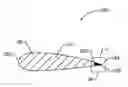
FIG. 1 is a perspective view of an airfoil of a gas turbine engine constructed in accordance with the present disclosure.
FIG. 2 is a cross-sectional view of the airfoil of FIG. 1 taken along the line 2-2 of FIG. 1, constructed in accordance with the present disclosure.
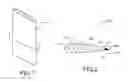
FIG. 3 is an exploded view of detail 3 of FIG. 2, illustrating a plating on a back side of the airfoil to produce a thin trailing edge, constructed in accordance with the present disclosure.
FIG. 4 is an exploded view similar to FIG. 3, but with the plating applied to the surface of an intact airfoil trailing edge, constructed in accordance with the present disclosure.
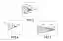
FIG. 5 is an exploded view similar to FIG. 4, but with the plating applied to the surface of a modified intact airfoil trailing edge, constructed in accordance with the present disclosure.
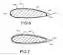
FIG. 6 is a cross-sectional view of the airfoil and similar to FIG. 2, but having the metal coating applied to all external surfaces of the airfoil, constructed in accordance with the present disclosure.
FIG. 7 is a cross-sectional view of the airfoil and similar to FIG. 6, but having an insulating layer between plating and the external surface of the airfoil, constructed in accordance with the present disclosure.
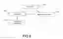
FIG. 8 is a flow chart illustrating steps involved in the fabrication of the airfoil, in accordance with a method of the present disclosure.
It should be understood that the drawings are not necessarily drawn to scale and that the disclosed embodiments are sometimes illustrated schematically and in partial views. It is to be further appreciated that the following detailed description is merely exemplary in nature and is not intended to limit the invention or the application and uses thereof. In this regard, it is to be additionally appreciated that the described embodiment is not limited to use with gas turbine engine airfoils. Hence, although the present disclosure is, for convenience of explanation, depicted and described as certain illustrative embodiments, it will be appreciated that it can be implemented in various other types of embodiments and in various other systems and environments.
DETAILED DESCRIPTION
Referring now to FIGS. 1 and 2, an airfoil 280 is shown. The airfoil 280 may be a rotating blade or a stator vane of a gas turbine engine. Alternatively, the airfoil 280 may be an airfoil for use in other applications such as, but not limited to, wind turbines, unmanned aerial vehicles (UAVs), micro-UAVs, race car down-force wings, missile wings, ballistic weapons, and guided weapons. The airfoil 280 may have a body portion 281, a leading edge 282, a trailing edge 284, a forward region 286, and a back side 288, as shown in FIG. 2. The leading edge 282 may be the portion of the airfoil 280 which first contacts (and separates) air, whereas the trailing edge 284 may be the portion of the airfoil where the separated air rejoins. By virtue of a high-modulus plating 290 at the trailing edge 284, the trailing edge 284 may have a minimum practical thickness which may advantageously eliminate or reduce undesirable bluff body close out shape at the trailing edge 284 as well as consequent drag-inducing flow separation and turbulent airflow (see further details below). Accordingly, the aerodynamic operation of the airfoil 280 may be substantially improved over current systems that lack such high-modulus platings at the airfoil trailing edge.
The body portion 281 of the airfoil 280 (i.e., the portion of the airfoil 280 which does not include the plating 290) may be formed from one or more lightweight and relatively low-modulus materials such as, but not limited to, aluminum, titanium, or an organic mesomorphous carbon (OMC) composite. As best shown in FIG. 3, the airfoil 280 may be truncated just prior to the start of the trailing edge 284 (i.e., at the back side 288) and the trailing edge 284 may be formed from the plating 290. The plating 290 may be formed from one or more layers of one or more high-modulus materials such as, but not limited to, nickel, iron, cobalt, and alloys of the foregoing elements comprising at least 50 wt. % of the alloy. The high-modulus nature of the material forming the plating 290 may enable a thinner trailing edge while maintaining necessary stiffness and resistance to flutter excitation and fatigue-induced cracking than could feasibly be produced with the lower-modulus materials forming the body portion 281 of the airfoil 280.
The plating 290 may be applied to a back surface 289 of the airfoil 280 by a metal deposition method apparent to those of ordinary skill in the art such as, but not limited to, electrolytic plating, electroless plating, brush plating, spray metal deposition, chemical vapor deposition, plasma vapor deposition, or a powder spray deposition process. The thickness of the plating 290 may range from about 0.001 inches (about 0.025 mm) near the tip of the trailing edge 284 to about 0.050 inches (about 1.3 mm) near the back side 288 of the airfoil 280, but other plating thicknesses may also apply. As one possible plating deposition method, the plating 290 may be initially deposited as a thick layer by one of the above-listed techniques and may be subsequently thinned and shaped in selected regions by a machining process or an abrasive grinding operation apparent to those of ordinary skill in the art. Such shaping techniques may enable the trailing edge 284 to be thinned and shaped to a minimum practical thickness.
As an alternative arrangement, the plating 290 may be deposited on an intact (non-truncated) trailing edge 284 of the airfoil 280 or it may be deposited on a modified intact trailing edge 284, as shown in FIGS. 4 and 5, respectively. In this way, the plating 290 may form an extension of the trailing edge 284 and may be thinned to a minimum practical thickness while maintaining necessary stiffness and fracture resistance.
The plating 290 may be applied to additional selected external surfaces of the airfoil 280 or to all external surfaces of the airfoil 280 such that the airfoil may be fully encased in the plating 290, as best shown in FIG. 6. Such an arrangement may be desired to eliminate an exposed bond-line edge between the material of the plating 290 and the material of the airfoil 280 which could otherwise present a potential delamination and peeling initiation point. If the airfoil 280 is encased in the plating 290, the plating 290 may be thinner near the forward regions 286 of the airfoil 280 and thicker near the back side 288, although other plating thickness variations may also be used.
In situations where the formation of strength-limiting or ductility-limiting phases (e.g., intermetallics) is expected at the interface between the surfaces of the airfoil 280 and the plating 290, or, in cases where galvanic corrosion at the interface of the airfoil 280 and the plating 290 is a concern, one or more insulating layers 292 may optionally be applied between the surfaces of the airfoil 280 and the plating 290 to produce a multi-layer structure, as shown in FIG. 7. The insulating layer 292 may prevent contact between the plating 290 and the surfaces of the airfoil 280 and thereby assist in preventing the formation of strength- or ductility-limiting phases and/or galvanic corrosion. The insulating layer 292 may be an adhesive, an epoxy material, a ceramic, or any other suitable material selected for such purposes by a skilled artisan. If necessary, the multi-layer structure shown in FIG. 7 may be brazed, transient liquid phase bonded, or diffusion bonded to form a more permanent joint between the airfoil 280 and the plating 290, as will be understood by those having ordinary skill in the art.
A method which may be employed for the fabrication of the airfoil 280 is shown in FIG. 8. Beginning with a first block 295, the airfoil 280 may be formed with a truncated trailing edge (see FIG. 3), an intact trailing edge (see FIG. 4), or a modified intact trailing edge (see FIG. 5) using a low-modulus material such as, but not limited to, aluminum, titanium, or composite material. Optionally, an insulating layer 292 may be applied to the surfaces of the airfoil 280 which are to be plated with the plating 290 according to an optional block 297. Whether or not an insulating layer 292 is applied, the plating 290, consisting of a high-modulus material, may be applied to selected surfaces of the airfoil 280 according to a block 299, as shown. The plating 290 may be applied by known metal deposition processes including, but not limited to, electrolytic plating, electroless plating, brush plating, spray metal deposition, chemical vapor deposition, plasma vapor deposition, or a powder spray deposition process. In this way, a trailing edge 284 may be built up on the back surface 289 of the airfoil 280 (see FIG. 3), or, the plating 290 may be deposited as an extension of an existing airfoil trailing edge (see FIGS. 4-5). Furthermore, the plating 290 may be deposited on additional or all external surfaces of the airfoil (see FIG. 6). The plating 290 may either be directly deposited such that a thin trailing edge is formed or it may be thinned and/or shaped at the trailing edge 284 or other selected regions as desired by a machining or abrasive grinding operation according to an optional block 301.
INDUSTRIAL APPLICABILITY
The present disclosure introduces a strategy for applying a thin plating of a high-modulus material to the trailing edge of an airfoil that is formed from a relatively low-modulus material to significantly improve the stiffness of the trailing edge, while allowing thinner practical trailing edges to be formed. Such stiffening of airfoil trailing edges, which are exposed to high-velocity airflow, pressure, and velocity pulses during operation, may improve the trailing edge fatigue life for a given thickness or may provide at least an equivalent fatigue life at reduced trailing edge thicknesses compared with current low-modulus airfoil materials. This technology may find wide industrial applicability in a wide range of areas including, but not limited to, gas turbine engines, unmanned aerial vehicles (UAVs), micro-UAVs, wind turbines, race car down-force wings, missile wings, ballistic weapons, and guided weapons.
Claims
What is claimed is:1. An airfoil, comprising:
a leading edge;
a body portion; and
a trailing edge formed from a high-modulus plating, the body portion being formed from a material that has a lower elastic modulus than the high-modulus plating.
2. The airfoil of claim 1, wherein the material forming the body portion is selected from the group consisting of aluminum, titanium, and a composite material.
3. The airfoil of claim 2, wherein the high-modulus plating is formed from one or more layers of a metal or a metal alloy selected from the group consisting of nickel, iron, cobalt, and an alloy of any of the foregoing elements comprising at least 50 wt. % of the alloy.
4. The airfoil of claim 1, wherein the body portion is truncated at a back side prior to the trailing edge, and wherein the high-modulus plating is applied to a back surface of the back side to form the trailing edge.
5. The airfoil of claim 4, wherein the high-modulus plating is applied to the back surface of the body portion by a method selected from the group consisting of electrolytic plating, electroless plating, brush plating, spray metal deposition, chemical vapor deposition, plasma vapor deposition, and a powder spray deposition process.
6. The airfoil of claim 4, wherein the high-modulus plating has a thickness of about 1.3 mm near the back surface of the body portion, and a thickness of about 0.025 mm near a tip of the trailing edge.
7. The airfoil of claim 1, wherein at least one surface of the body portion is plated with the high-modulus plating.
8. The airfoil of claim 7, further comprising an insulating layer between the body portion and the high-modulus plating.
9. The airfoil of claim 8, wherein the insulating layer is formed from a material selected from the group consisting of an adhesive, an epoxy material, and a ceramic.
10. An airfoil, comprising:
a body portion forming a leading edge and an intact trailing edge; and
a high-modulus plating applied to and forming an extension of the intact trailing edge.
11. The airfoil of claim 10, wherein the body portion is formed from a material selected from the group consisting of aluminum, titanium, and a composite material.
12. The airfoil of claim 11, wherein the high-modulus plating is formed from one or more layers of a metal or a metal alloy selected from the group consisting of nickel, iron, cobalt, and an alloy of any of the foregoing elements comprising at least 50 wt. % of the alloy.
13. The airfoil of claim 12, wherein the high-modulus plating is applied to the intact trailing edge by a method selected from the group consisting of electrolytic plating, electroless plating, brush plating, spray metal deposition, chemical vapor deposition, plasma vapor deposition, and a powder spray deposition process.
14. The airfoil of claim 13, wherein at least one surface of the body portion is plated with the high-modulus plating.
15. The airfoil of claim 14, further comprising an insulating layer between the body portion and the high-modulus plating.
16. A method for fabricating an airfoil, comprising:
forming a body portion of the airfoil; and
applying a high-modulus plating to the body portion to form a trailing edge, the body portion of the airfoil being formed from a material having a lower elastic modulus than the high-modulus plating.
17. The method of claim 16, wherein the material forming the body portion is selected from the group consisting of aluminum, titanium, and an composite material, and wherein the high-modulus plating is formed from one or more layers of a metal or a metal alloy selected from the group consisting of nickel, iron, cobalt, and an alloy of any of the foregoing elements comprising at least 50 wt. % of the alloy.
18. The method of claim 17, wherein forming the body portion of the airfoil comprises forming an airfoil that is truncated at a back side prior to the trailing edge, and wherein applying the high-modulus plating to the body portion to form the trailing edge comprises applying the high-modulus plating to a back surface of the back side.
19. The method of claim 17, wherein forming the body portion of the airfoil comprises forming an airfoil with an intact trailing edge, and wherein applying the high-modulus plating to the body portion to form the trailing edge comprises applying the high-modulus plating to the intact trailing edge to form an extension of the intact trailing edge.
20. The method of claim 17, further comprising shaping the high-modulus plating by machining or abrasive grinding.
Images & Drawings included:
Sources:
- United States Patent and Trademark Office - verify current appl. status at the USPTO↗
Recent applications in this class:
- » 20250250905 2025-08-07
Turbine Airfoil Coating - » 20250243770 2025-07-31
INTERNAL ALUMINIDE COATING FOR VANES AND BLADES AND METHOD OF MANUFACTURE - » 20250207502 2025-06-26
ROTOR BLADE, METHOD FOR MANUFACTURING A ROTOR BLADE AND A GAS TURBINE ENGINE - » 20250198294 2025-06-19
FAN BLADE LEADING EDGE SHEATH - » 20250179923 2025-06-05
GAS TURBINE ENGINE - » 20250092793 2025-03-20
Internal Aluminization of Coated Substrates - » 20250092792 2025-03-20
TURBINE ENGINE INCLUDING A GAS PATH COMPONENT HAVING A HYDROPHOBIC COATING - » 20250035001 2025-01-30
Components having coating systems comprising mud cracks and methods for forming the coating systems - » 20250027419 2025-01-23
METHOD OF MANUFACTURING A COMPONENT OF A GAS TURBINE ENGINE - » 20250020063 2025-01-16
SELECTIVE REMOVAL OF COATINGS FROM COOLING POCKETS OF TURBINE BLADES
Recent applications for this Assignee:
- » 20210317743 2021-10-14
Thermally isolated rotor systems and methods - » 20210310363 2021-10-07
Balanced composite root region for a blade of a gas turbine engine - » 20210283681 2021-09-16
Method for removing refractory metal cores - » 20210262415 2021-08-26
High bypass ratio engine bypass duct nozzle with controlled nozzle area - » 20210262400 2021-08-26
Speed limiting for power turbine governing and protection in a turboshaft engine - » 20210262359 2021-08-26
After-fan system with electrical motor for gas turbine engines - » 20210254494 2021-08-19
Vane arm torque transfer plate - » 20210254480 2021-08-19
Tangential rotor blade slot spacer for a gas turbine engine - » 20210254232 2021-08-19
THERMALLY STABLE NICKEL-PHOSPHORUS ALLOY FOR HIGH TEMPERATURE APPLICATIONS - » 20210246838 2021-08-12
Engine control device and methods thereof