Fuel lance cooling for a gas turbine with sequential combustion
US20160146468A1
2016-05-26
14/947,701
2015-11-20
✅ Patent granted
US 10,920,985 B2
2021-02-16
-
-
Todd E Manahan | Edwin Kang
Buchanan Ingersoll & Rooney PC
2036-11-29
Abstract:
A fuel lance is disclosed for injecting a gaseous and/or liquid fuel mixed with air into an axial hot gas flow flowing through a sequential combustor of a gas turbine, the fuel lance having at least one finger extending in a longitudinal direction into the axial hot gas flow of the gas turbine essentially perpendicular to the hot gas flow. The finger is configured as a streamlined body which has a streamlined cross-sectional profile. The body has two lateral surfaces essentially parallel to the axial hot gas flow. The body includes an enclosing outer wall having a longitudinally extending air plenum for the distributed introduction of air into the at least one finger. The air plenum is provided with a plurality of distributed impingement cooling holes, such that air exiting through the impingement cooling holes impinges on the inner side of the leading edge region of the body.
Inventors:
- Michael Düsing 14 🇩🇪 Rheinfelden, Germany
- Michael DÜSING 9 🇩🇪 Rheinfelden, Germany
- Urs Benz 44 🇨🇭 Gipf-Oberfrick, Switzerland
- Andre Theuer 22 🇨🇭 Baden, Switzerland
- Xianfeng Gao 4 🇨🇭 Niederrohrdorf, Switzerland
Assignee:
- General Electric Technology GmbH 781 🇨🇭 Baden, Switzerland
- ANSALDO ENERGIA SWITZERLAND AG 188 🇨🇭 Baden, Switzerland
Applicant:
Interested in similar patents?
Get notified when new applications in this technology area are published.
Classification:
F02C7/222 » CPC further
Features, components parts, details or accessories, not provided for in, or of interest apart form groups - ; Air intakes for jet-propulsion plants; Fuel supply systems Fuel flow conduits, e.g. manifolds
F23R2900/03044 » CPC further
Special features of, or arrangements for continuous combustion chambers; Combustion processes therefor Impingement cooled combustion chamber walls or subassemblies
F23R2900/03341 » CPC further
Special features of, or arrangements for continuous combustion chambers; Combustion processes therefor Sequential combustion chambers or burners
F23R3/28 IPC
Continuous combustion chambers using liquid or gaseous fuel characterised by the fuel supply
F23R3/283 » CPC main
Continuous combustion chambers using liquid or gaseous fuel characterised by the fuel supply Attaching or cooling of fuel injecting means including supports for fuel injectors, stems, or lances
F02C7/22 IPC
Features, components parts, details or accessories, not provided for in, or of interest apart form groups - ; Air intakes for jet-propulsion plants Fuel supply systems
F23C7/002 » CPC further
Combustion apparatus characterised by arrangements for air supply the air being submitted to a rotary or spinning motion
F23R3/286 » CPC further
Continuous combustion chambers using liquid or gaseous fuel characterised by the fuel supply having fuel-air premixing devices
Y02T50/60 » CPC further
Aeronautics or air transport Efficient propulsion technologies, e.g. for aircraft
Y02T50/60 » CPC further
Aeronautics or air transport Efficient propulsion technologies, e.g. for aircraft
F23R3/00 IPC
Continuous combustion chambers using liquid or gaseous fuel
F23C7/00 IPC
Combustion apparatus characterised by arrangements for air supply
F23R3/12 » CPC further
Continuous combustion chambers using liquid or gaseous fuel characterised by the air-flow or gas-flow configuration; Air inlet arrangements for primary air inducing a vortex
F23R3/18 » CPC further
Continuous combustion chambers using liquid or gaseous fuel characterised by the air-flow or gas-flow configuration with devices inside the flame tube or the combustion chamber to influence the air or gas flow Flame stabilising means, e.g. flame holders for after-burners of jet-propulsion plants
F23R3/20 » CPC further
Continuous combustion chambers using liquid or gaseous fuel characterised by the air-flow or gas-flow configuration with devices inside the flame tube or the combustion chamber to influence the air or gas flow; Flame stabilising means, e.g. flame holders for after-burners of jet-propulsion plants incorporating fuel injection means
F23R3/16 » CPC further
Continuous combustion chambers using liquid or gaseous fuel characterised by the air-flow or gas-flow configuration with devices inside the flame tube or the combustion chamber to influence the air or gas flow
Description
BACKGROUND OF THE INVENTION
The present invention relates to the technology of gas turbines with sequential combustion. It refers to a fuel lance cooling according to the preamble of claim 1.
PRIOR ART
In order to achieve a high efficiency, a high turbine inlet temperature is required in standard gas turbines. As a result, there arise high NOx emission levels and high life cycle costs. These problems can be mitigated with a sequential combustion cycle, wherein the compressor delivers nearly double the pressure ratio of a conventional one. The main flow passes the first combustion chamber (e.g. using a burner of the general type as disclosed in EP 1 257 809 or as in U.S. Pat. No. 4,932,861, also called EV combustor, where the EV stands for environmental), wherein a part of the fuel is combusted. After expanding at the high-pressure turbine stage, the remaining fuel is added and combusted (e.g. using a burner of the type as disclosed in U.S. Pat. No. 5,431,018 or U.S. Pat. No. 5,626,017 or in US 2002/0187448, also called SEV combustor, where the S stands for sequential). Both combustors contain premixing burners, as low NOx emissions require high mixing quality of the fuel and the oxidizer.
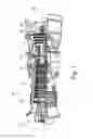
An exemplary gas turbine of the applicant with sequential combustion, which is known as GT26, is shown in FIG. 1.
Gas turbine 10 of FIG. 1 comprises a rotor 11 with a plurality of blades rotating about a machine axis 20 and being surrounded by a casing 12. Air is taken in at air inlet 13 and is compressed by compressor 14. The compressed air is used to burn a first fuel in a first (annular) combustor 15, thereby generating hot gas. The hot gas drives a first, high pressure (HP) turbine 16, is then reheated in a second (annular, sequential) combustor 17, drives a second, low pressure (LP) turbine 18 and exits gas turbine 10 through exhaust gas outlet 19.
Since the second combustor 17 is fed by expanded exhaust gas of the first combustor 15, the operating conditions allow self ignition (spontaneous ignition) of the fuel air mixture without additional energy being supplied to the mixture. To prevent ignition of the fuel air mixture in the mixing region, the residence time therein must not exceed the auto ignition delay time. This criterion ensures flame-free zones inside the burner. This criterion poses challenges in obtaining appropriate distribution of the fuel across the burner exit area. SEV-burners are currently designed for operation on natural gas and oil only. Therefore, the momentum flux of the fuel is adjusted relative to the momentum flux of the main flow so as to penetrate into the vortices. The subsequent mixing of the fuel and the oxidizer at the exit of the mixing zone is just sufficient to allow low NOx emissions (mixing quality) and avoid flashback (residence time), which may be caused by auto ignition of the fuel air mixture in the mixing zone. The cross flow injection concept used in the current SEV-fuel injection devices (SEV fuel lances) necessitates high-pressure carrier air supply, which reduces the overall efficiency of the power plant.
Document WO 2011/054760 A1 discloses a burner for a combustion chamber of a turbine, with an injection device for the introduction of at least one fuel into the burner. The injection device has at least one body arranged in the burner with at least two nozzles for introducing the fuel into the chamber, the body having a streamlined cross-sectional profile extending with a longitudinal direction perpendicularly to a main flow direction prevailing in the burner and two lateral surfaces essentially parallel to the main flow direction joined at their upstream side by a leading edge and joined at their downstream side forming a trailing edge, the nozzles being distributed along said trailing edge. The body comprises an enclosing outer wall defining said streamlined cross-sectional profile, wherein within this outer wall, there is provided a longitudinal inner air plenum for the introduction of air into the injection device. The air plenum is provided with holes such that air exiting through these holes impinges the inner side of the leading edge.
The document is limited to injection devices with external vortex generators. Other means for enhancing fuel/air mixing, especially lobes between the nozzles, are not disclosed.
Furthermore, the document fails to teach geometric details of the impingement cooling, which are essential for a successful operation of such a device.
SUMMARY OF THE INVENTION
It is an object of the present invention to provide impingement cooling details, which are not only applicable to lances with vortex generators, but also to lances with lobes between the fuel nozzles at the trailing edge.
It is another object of the present invention to provide impingement cooling details, which are equally suitable for rectangular burners and annular or center-body burners.
These and other objects are obtained by a fuel lance according to claim 1.
The invention relates to a fuel lance for injecting a gaseous and/or liquid fuel mixed with air into an axial hot gas flow flowing through a sequential combustor of a gas turbine, said fuel lance comprising at least one finger extending in a longitudinal direction into said axial hot gas flow of said gas turbine essentially perpendicular to said hot gas flow;
-
- wherein said at least one finger is configured as a streamlined body which has a streamlined cross-sectional profile;
- wherein said body has two lateral surfaces essentially parallel to said axial hot gas flow, joined at their upstream side by a leading edge and joined at their downstream side forming a trailing edge;
- wherein a plurality of nozzles for injecting a gaseous and/or liquid fuel mixed with air is distributed along said trailing edge;
- wherein means for improving the mixing quality and reducing pressure loss in said sequential combustor are provided in the trailing edge region of said body;
- wherein said body comprises an enclosing outer wall defining said streamlined cross-sectional profile,
- wherein within said outer wall there is provided a longitudinally extending air plenum for the distributed introduction of air into said at least one finger, said air plenum having a distance from said outer wall, defining a first interspace; and
- wherein said air plenum is provided with a plurality of distributed impingement cooling holes, such that air exiting through said impingement cooling holes impinges on the inner side of the leading edge region of said body.
It is characterized in that said impingement cooling holes each have a hole diameter between 1.2 and 1.8 mm; and said impingement cooling holes are arranged at said air plenum with a pitch ratio, i.e. the ratio of the distance between said holes and the hole diameter, between 3 and 10.
According to an embodiment of the invention within said outer wall there is provided a longitudinally extending gas plenum for the distributed introduction of gaseous fuel into said at least one finger and said gas plenum is arranged in the middle between said leading edge and said trailing edge with a distance from said outer wall, defining a second interspace for the delivery of air from said air plenum to said leading edge.
Specifically, a plurality of distributed pin fins is arranged on the inner side of said outer wall of said streamlined body in the region of said gas plenum for convective cooling of said outer wall by the air flowing from said air plenum to said trailing edge region through said second interspace between said gas plenum and said outer wall; and said pin fins have a height perpendicular to said outer wall of between 1.5 and 2.5 mm, and said pin fins have a pitch ratio of between 3 and 5.
More specifically, said pin fins are cylindrical or tapered or hoof-shaped or have the form of teardrop pins.
Specifically, a plurality of distributed effusion cooling holes is provided in said outer wall at the trailing edge region, through which air from said air plenum exits said streamlined body after having convectively cooled said outer wall in said second interspace.
According to another embodiment of the invention said means for improving the mixing quality and reducing pressure loss in said sequential combustor comprises a plurality of vortex generators arranged on said streamlined body on both sides at the trailing edge region.
According to a further embodiment of the invention said means for improving the mixing quality and reducing pressure loss in said sequential combustor comprises lobes being arranged between said nozzles at the trailing edge of said streamlined body.
According to just another embodiment of the invention said fuel lance is configured for a rectangular burner.
Alternatively, said fuel lance is configured for a center-body burner.
According to another embodiment of the invention the height of the first interspace between said air plenum and said outer wall perpendicular to said outer wall increases from said leading edge towards said trailing edge of said streamlined body in order to reduce cross flow velocity and improve impingement cooling efficiency downstream.
A further improvement for a fuel lance with vortex generators is achieved by each of said vortex generators comprising a leading panel, and providing guiding ribs at said vortex generators in order to guide an air flow closer to said leading panels.
According to a further embodiment of the invention air is feed to said air plenum from both sides of said air plenum, and a flow separator is provided in the longitudinal middle of said air plenum to separate said air flows from both sides in order to avoid instabilities.
According to another embodiment of the invention ribs are provided in lances with a gas plenum at said second interspace between said gas plenum and said outer wall for improving convective cooling in this region.
According to just another embodiment of the invention a bypass is provided in lances with a gas plenum at said air plenum through which bypass air flows from said air plenum into said second interspace independent of said impingement cooling holes.
According to a further embodiment of the invention release holes are provided in a lance with gas plenum in the outer wall at the downstream end of said gas plenum to destroy dead air flow corner behind said gas plenum.
A further improvement for a fuel lance with vortex generators is achieved by having said vortex generators made of a ceramic.
BRIEF DESCRIPTION OF THE DRAWINGS
The present invention is now to be explained more closely by means of different embodiments and with reference to the attached drawings.
FIG. 1 shows in a perspective view an exemplary gas turbine with sequential combustion of the type GT26;
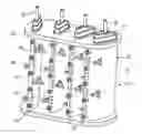
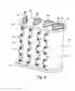
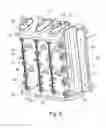
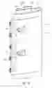
FIG. 2 shows in a perspective view a vortex generator (VG) lance for a rectangular burner according to an embodiment of the invention;
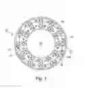
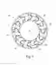
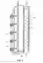
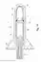
FIG. 3 shows in an axial view a VG lance for a center-body burner according to an embodiment of the invention;
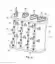
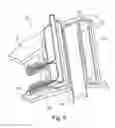
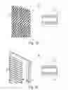
FIG. 4 shows in a perspective view similar to FIG. 2 a lobe lance for a rectangular burner according to an embodiment of the invention;
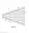
FIG. 5 shows in an axial view similar to FIG. 3 a lobe lance for a center-body burner according to an embodiment of the invention;
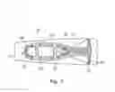
FIG. 6 shows a vertical section through a finger of a center-body lobe lance according to an embodiment of the invention;
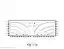
FIG. 7 shows a horizontal section through the finger of FIG. 6;
FIG. 8 shows in a perspective view the rectangular VG lance of FIG. 2 with one finger being vertically sectioned;
FIG. 9 shows in detail the sectioned finger of FIG. 8;
FIG. 10 shows a detail of a vortex generator of the VG lance with additional ribs according to another embodiment of the invention;
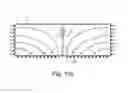
FIG. 11a, FIG. 11b show the possibility of feeding air to the air plenum from both sides (FIG. 11a) and separating the flows be means of a flow separator according to another embodiment of the invention (FIG. 11b);
FIG. 12 shows additional oblique ribs for enhanced convection cooling in the gas plenum region of the lance according to another embodiment of the invention;
FIG. 13 shows additional lateral ribs for enhanced convection cooling in the gas plenum region of the lance according to another embodiment of the invention;
FIG. 14 shows in a horizontal section of a VG lance the possibility of bypassing air from the air plenum according to another embodiment of the invention; and
FIG. 15 shows the provision of additional release holes at the downstream corner of the gas plenum according to another embodiment of the invention.
DETAILED DESCRIPTION OF DIFFERENT EMBODIMENTS OF THE INVENTION
The constant pressure sequential combustion consists of two combustors (see FIG. 1 of the gas turbine GT26). Implementation of the sequential combustors improves combustion performance and operation flexibility.
However, there are still problems to improve series cooling systems in sequential burners with impingement cooling, convective cooling and effusion cooling for a complicated structure with fuel gas and fuel oil plenum included. It is thus a desire to achieve optimized cooling, good mixing with hot gas flow and a required lifetime with minimal cooling air for lances used in these burners.
A VG lance concept was already developed to improve the mixing quality and reduce the SEV pressure loss and further adapted to a VG lance development for a rectangular burner and for a center-body burner. The same was done for a lobe lance for a rectangular burner and for a center-body burner.
According to the present invention the internal structure and cooling system of these lances are improved as explained below.
FIG. 2 and FIG. 3 show VG lances 21 and 32 for rectangular burner (FIG. 2) and a center-body burner (FIG. 3). VG lance 21 of FIG. 2 comprises four separate fingers 22 extending in parallel between an upper plate 25 and a lower plate 26. Each finger 22 is configured as a streamlined body which has a streamlined cross-sectional profile (like an airfoil). The body has two lateral surfaces essentially parallel to an axial hot gas flow, which passes through the lance between upper and lower plates 25, 26. The lateral surfaces are joined at their upstream side by a leading edge 23 and joined at their downstream side forming a trailing edge 24.
A plurality of nozzles 27 for injecting a gaseous and/or liquid fuel mixed with air is distributed along the trailing edge 24. Means for improving the mixing quality and reducing pressure loss in said sequential combustor are provided in the trailing edge region of said body in form of a plurality of vortex generators 28 arranged on the streamlined body on both sides at the trailing edge region.
The streamlined body comprises an enclosing outer wall 75 defining its streamlined cross-sectional profile. Within the outer wall 75 a longitudinally extending air plenum 31 is provided having a distance from outer wall 75, defining a first interspace, for the distributed introduction of air into each finger 22 (see FIG. 8). There is also provided a longitudinally extending gas plenum 30 for the distributed introduction of gaseous fuel into each finger 22. Gas plenum 30 is arranged in the middle between leading edge 23 and trailing edge 24 with a distance from outer wall 75, defining a second interspace for the delivery of air from air plenum 31 to leading edge 23. Liquid fuel (oil) can be introduced by liquid fuel supply 29.
A similar internal structure exists for center-body VG lance 32 of FIG. 3 with its radial fingers 35 extending between an outer ring 33 and a center-body 34, each finger being equipped with nozzles 36 and vortex generators 37.
The cooling air introduced through the air plenum 31 is guided through the lances 21, 32, first cools the leading edge 23 of the VG lances 21, 32 with impingement cooling and reduces heat load with TBC coating (or without TBC coating), and then cools the trailing edge 24 of the VG lances 21, 32 by using convective cooling with internal pins (67 in FIG. 7), and finally is discharged into the hot gas flow through slots between the nozzles 27, 36 and fuel nozzles 27, 36 (as carrier air) and locally discharged to establish effusion cooling.
A similar situation is given for the lobe lances 38 and 49 of FIG. 4 and FIG. 5 to be used with a rectangular burner (FIG. 4) and a center-body burner (FIG. 5). Lobe lance 38 of FIG. 4 comprises four separate fingers 39 extending in parallel between an upper plate 42 and a lower plate 43. Each finger 39 is configured as a streamlined body which has a streamlined cross-sectional profile (like an airfoil).
The body has two lateral surfaces essentially parallel to an axial hot gas flow, which passes through the lance between upper and lower plates 42, 43. The lateral surfaces are joined at their upstream side by a leading edge 40 and joined at their downstream side forming a trailing edge 41.
A plurality of nozzles 44 for injecting a gaseous and/or liquid fuel mixed with air are distributed along the trailing edge 41. Means for improving the mixing quality and reducing pressure loss in said sequential combustor are provided in the trailing edge region of said body in form of lobes 45 running between the nozzles 44 at the trailing edge 41.
The streamlined body comprises an enclosing outer wall defining its streamlined cross-sectional profile. Within the outer wall a longitudinally extending air plenum 48 is provided having a distance from outer wall, defining a first interspace, for the distributed introduction of air into each finger 39 (see finger 52 in FIGS. 6 and 7).
There is also provided a longitudinally extending gas plenum 47 for the distributed introduction of gaseous fuel into each finger 39. Gas plenum 47 is arranged in the middle between leading edge 40 and trailing edge 41 with a distance from outer wall, defining a second interspace for the delivery of air from air plenum 48 to leading edge 40. Liquid fuel (oil) can be introduced by liquid fuel supply 46.
A similar internal structure exists for center-body lobe lance 49 of FIG. 5 with its radial fingers 52 extending between an outer ring 50 and a center-body 51, each finger being equipped with nozzles 53 and lobes 54 between nozzles 53.
Details of a lobe lance finger 52 for a center-body burner are shown in FIGS. 6 and 7. Finger 52 extends between an inner plate 64 and an outer plate 65 an comprises an air plenum 55 and a gas plenum 56, which are enclosed by outer wall 75 with leading edge 61 and trailing edge 61.
The cooling air introduced through the air plenum 55 is guided in longitudinal direction through finger 52, first cools the leading edge 61 of the body by means of impingement cooling 58 and reduces heat load with TBC coating (or without TBC coating), and then cools the downstream parts of the body by means of convective cooling 59 with internal pins 67 arranged on the inner side of outer wall 75, and finally is discharged into the hot gas flow through slots between the nozzles 53 and fuel nozzles 53 (as carrier air).
Characteristic features of the new and improved cooling scheme of the VG lances shown in FIG. 2, FIG. 3 and FIG. 8, FIG. 9 are the following:
-
- A series cooling system for a fuel injection lance (including fuel gas plenum 30 and fuel oil plenum 29).
- Leading edge 23 is impingement cooled with impingement cooling holes 66
(FIG. 9): The impingement cooling hole diameter is in the range 1.2 to 1.8 mm, the pitch ratio (ratio of distance between hoes/hole diameter) is in the range 3 to 10.
-
- The mid body and trailing edge 24 is convectively cooled with pin fins 67 (FIG. 14): pin fin height is in the range 1.5 to ˜2.5 mm, pitch ratio is in the range 3 to 5 (ratio of distance between pin fins/pin fin diameter).
- Pin fins 67 can be cylindrical, tapered, hoof shaped, or tear dropped.
- The region, where the vortex generators 28 are arranged, is effusion cooled. Effusion cooling hole diameter is in the region 0.7 to 1.2 mm, pattern of effusion cooling holes 68 (FIG. 8) has a ratio of distance to hole diameter in the range 4 to 15.
- The cooling flows are finally discharged through slots between nozzles 27, rings of nozzles 27 (function as carrier air) and the effusion cooling.
The VG lance cooling can be further improved by:
-
- The impingement cooling channel height (height of interspace between air plenum 31 and outer wall 75) can vary axially (not necessarily constant height) and especially in downstream direction to optimize the cross cooling flows
- As shown in FIGS. 12 and 13 vortex generators, straight ribs, V-shaped or W-shaped ribs 71 (FIG. 12) can be applied on the mid body and the trailing edge of the cooling channels to improve the cooling situation there instead of pins
- Axially directional ribs or flow splitter 72 (FIG. 13) can be applied on mid body and trailing edge to optimize cooling flows
- Film cooling holes or effusion cooling holes can additionally be applied on some hot spots
- As shown in FIG. 14, the cooling air can be bypassed as bypass air 74 from air plenum 31 to the mid body without passing through the impingement cooling holes 66. This helps to optimize the cooling between leading edge 23 and trailing edge 24 and optimize the back flow margin which is required by the effusion cooling flows
- Vortex generators 28 can be replaced with ceramics, and therefore the cooling of vortex generators 28 is not required anymore
For the lobe lances shown in FIG. 4, 5 and FIG. 6, 7 the situation is similar:
-
- A series cooling system for a fuel injection lance (including fuel gas plenum 47 and fuel oil plenum 46)
- Leading edge 40 is impingement cooled: impingement cooling hole diameter is in rage 1.2 to 1.8 mm, pitch ratio (ratio of distance between holes/hole diameter) is in range 3 to 10
- The mid body and trailing edge 41 is convectively cooled with pin fins 67: pin fin height is in range 1.5 to 2.5 mm, pitch ratio is in range 3 to 5 (ratio of distance between pin fins/pin fin diameter)
- Pin fins 67 can be cylindrical, tapered, hoof shaped, or tear dropped
- The cooling flows are finally discharged through slot between nozzles 44, rings of nozzles 44 (function as carrier air) and locally effusion cooling if needed for hot spot.
The lobe lance cooling can be further improved:
-
- The impingement cooling channel height can vary axially (not necessarily constant height), especially increase in downstream direction, to optimize the cross cooling flows
- Vortex generators, Straight ribs, V shaped or W shaped ribs (71 in FIG. 12) can be applied on the mid body and the trailing edge 41 of the cooling channels to improve the cooling situation there instead of pins
- Axially directional ribs or flow splitters (72 in FIG. 13) can be applied on mid body and trailing edge 41 to optimize cooling flows
- Film cooling holes or effusion cooling holes can be applied on some hot spots
- As shown in FIG. 14, the cooling air can be bypassed as bypass air 74 from air plenum 48 to the mid body without passing through the impingement cooling holes 66. This helps to optimize the cooling between leading edge 40 and trailing edge 41 and optimize the back flow margin which is required by the effusion cooling flows
Other possible improvements are the following:
-
- As shown in FIG. 10, guiding ribs 70a, 70b may be provided at each vortex generator 28 to guide air flow closer to the leading panel 69 of vortex generator 28, as the leading panel can not be well cooled due to very low hot gas back flow margin (BfM) without such guiding ribs 70a, 70b
- As shown in FIG. 11, the air plenum 31 is fed with air form both ends (see also FIG. 9). As collision of two counter air flows can cause an instability, a flow separator 76 may be provided at the longitudinal middle of the air plenum to avoid these counterflows
- As shown in FIG. 15, additional release holes 73 are provided between vortex generators 28 and nozzles 27 to destroy the dead air flow corner behind the fuel gas plenum 30 and increase the cooling velocity of this area for better cooling; these release holes 73 work as film cooling holes as well
LIST OF REFERENCE NUMERALS
10 gas turbine (GT, e.g. GT26)
11 rotor
12 casing
13 air inlet
14 compressor
15 combustor (annular, e.g. EV)
16 high pressure (HT) turbine
17 combustor (annular, sequential, e.g. SEV)
18 low pressure (LP) turbine
19 exhaust gas outlet
20 machine axis
21 lance (vortex generator VG; rectangular burner)
22,39 finger
23,40 leading edge
24,41 trailing edge
25,42 upper plate
26,43 lower plate
27,44 nozzle
28,37 vortex generator (VG)
29,46 liquid fuel supply (fuel oil plenum)
30,47,56 gas plenum
31,48,55 air plenum
32 lance (VG; center-body burner)
33,50 outer ring
34,51 center-body
35,52 finger
36,53 nozzle
38 lance (lobe)
45,54 lobe
49 lance (lobe; center-body burner)
57 liquid fuel supply
58 impingement cooling
59 convective cooling
60 effusion cooling
61 leading edge
62 trailing edge
64 inner plate
65 outer plate
66 impingement cooling hole
67 pin fin
68 effusion cooling hole
69 leading panel (VG)
70a, 70b guiding rib
71,72 rib
73 release hole
74 bypass air
75 outer wall
76 flow separator
Claims
1. Fuel lance for injecting a gaseous and/or liquid fuel mixed with air into an axial hot gas flow flowing through a sequential combustor of a gas turbine, said fuel lance comprising:
at least one finger configured for extending in a longitudinal direction into said axial hot gas flow of a gas turbine essentially perpendicular to said hot gas flow;
wherein said at least one finger is configured as a streamlined body which has a streamlined cross-sectional profile;
wherein said body has two lateral surfaces arranged to be essentially parallel to said axial hot gas flow, joined at their upstream side by a leading edge and joined at their downstream side forming a trailing edge;
wherein a plurality of nozzles for injecting a gaseous and/or liquid fuel mixed with air are distributed along said trailing edge;
wherein means for impacting the mixing quality and reducing pressure loss in said sequential combustor are provided in the trailing edge region of said body;
wherein said body includes an enclosing outer wall defining said streamlined cross-sectional profile,
wherein within said outer wall there is provided a longitudinally extending air plenum for the distributed introduction of air into said at least one finger, said air plenum having a distance from said outer wall, defining a first interspace; and
wherein said air plenum is provided with a plurality of distributed impingement cooling holes, such that air exiting through said impingement cooling holes impinges on the inner side of the leading edge region of said body;
wherein
said impingement cooling holes each have a hole diameter between 1.2 and 1.8 mm; and
said impingement cooling holes are arranged at said air plenum with a pitch ratio, of the distance between said holes and the hole diameter, of between 3 and 10.
2. Fuel lance according to claim 1, wherein
within said outer wall there is provided a longitudinally extending gas plenum for the distributed introduction of gaseous fuel into said at least one finger,
said gas plenum being arranged in the middle between said leading edge and said trailing edge with a distance from said outer wall, defining a second interspace for the delivery of air from said air plenum to said leading edge.
3. Fuel lance according to claim 2, wherein
a plurality of distributed pin fins are arranged on the inner side of said outer wall of said streamlined body in the region of said gas plenum for convective cooling of said outer wall by the air flowing from said air plenum to said trailing edge region through said second interspace between said gas plenum and said outer wall; and
said pin fins have a height perpendicular to said outer wall of between 1.5 and 2.5 mm, and
said pin fins have a pitch ratio of between 3 and 5.
4. Fuel lance according to claim 3, wherein said pin fins are cylindrical or tapered or hoof-shaped or have the form of teardrop pins.
5. Fuel lance according to claim 3, wherein a plurality of distributed effusion cooling holes are provided in said outer wall at the trailing edge region, through which air from said air plenum exits said streamlined body after having convectively cooled said outer wall in said second interspace.
6. Fuel lance according to claim 1, wherein said means for impacting the mixing quality and reducing pressure loss in said sequential combustor comprises:
a plurality of vortex generators arranged on said streamlined body on both sides at the trailing edge region.
7. Fuel lance according to claim 1, wherein said means for impacting the mixing quality and reducing pressure loss in said sequential combustor comprises:
lobes being arranged between said nozzles at the trailing edge of said streamlined body.
8. Fuel lance according to claim 1, wherein said fuel lance is configured for a rectangular burner.
9. Fuel lance according to claim 1, wherein said fuel lance is configured for a center-body burner.
10. Fuel lance according to claim 1, wherein the height of the first interspace between said air plenum and said outer wall perpendicular to said outer wall increases from said leading edge towards said trailing edge of said streamlined body in order to reduce cross flow velocity and enhance impingement cooling efficiency downstream.
11. Fuel lance according to claim 6, wherein each of said vortex generators comprises:
a leading panel, and guiding ribs at said vortex generators in order to guide an air flow closer to said leading panels.
12. Fuel lance according to claim 1, wherein
air is feed to said air plenum from both sides of said air plenum, and
a flow separator is provided in the longitudinal middle of said air plenum to separate said air flows from both sides in order to avoid instabilities.
13. Fuel lance according to claim 2, wherein ribs are provided at said second interspace between said gas plenum and said outer wall for enhancing convective cooling in this region.
14. Fuel lance according to claim 2, wherein a bypass is provided at said air plenum through which bypass air flows from said air plenum into said second interspace independent of said impingement cooling holes.
15. Fuel lance according to claim 2, wherein release holes are provided in the outer wall at the downstream end of said gas plenum to avoid a dead air flow corner behind said gas plenum.
16. Fuel lance according to claim 6, wherein said vortex generators are made of a ceramic.
Images & Drawings included:
Sources:
- United States Patent and Trademark Office - verify current appl. status at the USPTO↗
Recent applications in this class:
- » 20250283601 2025-09-11
CONTINUOUS FLOW FUEL SYSTEM - » 20250277585 2025-09-04
COMBUSTOR SIZE RATING FOR A GAS TURBINE ENGINE USING HYDROGEN FUEL - » 20250257873 2025-08-14
COOLING IN STAGED FUEL SYSTEMS - » 20250251133 2025-08-07
TURBINE ENGINE HAVING A COMBUSTION SECTION WITH A FUEL SUPPLY ASSEMBLY - » 20250251132 2025-08-07
FUEL INJECTOR COMBUSTION SEAL ASSEMBLY - » 20250224114 2025-07-10
FUEL INJECTOR - » 20250216081 2025-07-03
COMBUSTOR WITH ADJUSTABLE AIR FLOW FOR AXIAL FUEL STAGE INJECTOR AND HEAD END FUEL NOZZLE ASSEMBLY - » 20250207779 2025-06-26
INJECTOR HEAD FOR FUEL INJECTOR - » 20250172293 2025-05-29
ASSEMBLY, METHOD FOR MANUFACTURING ASSEMBLY, BURNER, AND METHOD FOR MANUFACTURING BURNER - » 20250084994 2025-03-13
PLASMA INJECTION MODULES
Recent applications for this Assignee:
- » 20240378493 2024-11-14
SYSTEMS AND METHODS FOR PERFORMING MACHINE LEARNING AND DATA ANALYTICS IN HYBRID SYSTEMS - » 20240369646 2024-11-07
SYSTEMS AND METHODS FOR MONITORING A THROUGH FAULT CURRENT - » 20240348047 2024-10-17
SYSTEMS AND METHODS FOR MALICIOUS CONTROL DETECTION IN A POWER GRID - » 20240319253 2024-09-26
SYSTEMS AND METHODS FOR DETERMINING A DISTANCE TO A FAULT IN HYBRID LINE SYSTEMS - » 20240319252 2024-09-26
SYSTEMS AND METHODS FOR DETERMINING A DISTANCE TO A FAULT IN A POWER SYSTEMS NETWORK - » 20240274384 2024-08-15
FAST EARTHING SWITCH IMPLEMENTING THE COANDA EFFECT - » 20240266129 2024-08-08
CIRCUIT BREAKER COMPRISING AN IMPROVED GAS FLOW MANAGEMENT - » 20240258049 2024-08-01
SF6 FREE GAS INSULATED DISCONNECTOR WITH LIMITED ARCING VOLUME - » 20240229683 2024-07-11
SYSTEM FOR READYING SUB-CRITICAL AND SUPER-CRITICAL STEAM GENERATOR, SERVICING METHOD OF SAID SUB-CRITICAL AND SUPER-CRITICAL STEAM GENERATOR AND METHOD OF OPERATION OF SUB-CRITICAL AND SUPER-CRITICAL STEAM GENERATOR - » 20240151762 2024-05-09
Systems and methods for identifying grid fault type and faulted phase