READY-TO-ASSEMBLE HOUSE
US20160168845A1
2016-06-16
15/014,958
2016-02-03
Abstract:
A ready-to-assemble house having sufficient strength includes a column member and wall members that are made of cardboard or heavy paper. A side end portion of the wall member is fixed to the column member. A side end portion of the wall member is fixed to a side end portion of the wall member. A side end portion of the wall member is fixed to a side end portion of the wall member. A side end portion and a side end portion of the wall member are respectively fixed to a side end portion of the wall member and the side end portion of the wall member. The column member is configured to become shaped as a rectangular column by being folded along folding lines.
Assignee:
- DAIKI CO., LTD. 72 🇯🇵 Tokyo, Japan
Interested in similar patents?
Get notified when new applications in this technology area are published.
Classification:
E04B1/34357 » CPC main
Constructions in general; Structures which are not restricted either to walls, e.g. partitions, or floors or ceilings or roofs; Structures characterised by movable, separable, or collapsible parts, e.g. for transport Foldable or retractable structures
E04B1/34331 » CPC further
Constructions in general; Structures which are not restricted either to walls, e.g. partitions, or floors or ceilings or roofs; Structures characterised by movable, separable, or collapsible parts, e.g. for transport characterised by separable parts mainly constituted by threedimensional elements
E04C2/46 » CPC further
Building elements of relatively thin form for the construction of parts of buildings, e.g. sheet materials, slabs, or panels characterised by the purpose specially adapted for making walls
E04H1/005 » CPC further
Buildings or groups of buildings for dwelling or office purposes; General layout, e.g. modular co-ordination, staggered storeys small buildings Modulation co-ordination
E04B1/343 IPC
Constructions in general; Structures which are not restricted either to walls, e.g. partitions, or floors or ceilings or roofs Structures characterised by movable, separable, or collapsible parts, e.g. for transport
E04H1/02 » CPC further
Buildings or groups of buildings for dwelling or office purposes; General layout, e.g. modular co-ordination, staggered storeys small buildings Dwelling houses; Buildings for temporary habitation, e.g. summer houses
E04C2/38 » CPC further
Building elements of relatively thin form for the construction of parts of buildings, e.g. sheet materials, slabs, or panels characterised by the shape or structure with attached ribs, flanges, or the like, e.g. framed panels
E04H1/00 IPC
Buildings or groups of buildings for dwelling or office purposes; General layout, e.g. modular co-ordination, staggered storeys small buildings
E04C2/32 » CPC further
Building elements of relatively thin form for the construction of parts of buildings, e.g. sheet materials, slabs, or panels characterised by the shape or structure formed of corrugated or otherwise indented sheet-like material; composed of such layers with or without layers of flat sheet-like material
E04B2/00 IPC
Walls, e.g. partitions, for buildings; Wall construction with regard to insulation; Connections specially adapted to walls
Description
CROSS REFERENCE TO RELATED APPLICATION
This is a Continuation of International Application No. PCT/JP2013/082347 filed Dec. 2, 2013, which claims the benefit of Japanese Applications No. 2013-194114 filed Sep. 19, 2013, and No. 2013-213716 filed Oct. 11, 2013. The contents of these applications are hereby incorporated by reference in their entirety.
TECHNICAL FIELD
The present invention relates to a ready-to-assemble house made of paper.
BACKGROUND ART
When a disaster such as an earthquake has occurred, there are cases where a large number of disaster victims are forced to live together in a single evacuation shelter. In order to relieve the psychological burden on the disaster victims even a small amount at such an evacuation shelter, there is desire to retain private space for the disaster victims. A means for retaining such private space is disclosed in Patent Literature 1, for example. This literature discloses the creation of partitions by folding a single piece of cardboard in order to divide the space between disaster victims.
CITATION LIST
Patent Literature
[PLT 1] JP 2010-255238A
SUMMARY OF INVENTION
Technical Problem
The partitions in Patent Literature 1 retain a minimum level of private space, which makes it possible to relieve the psychological burden on disaster victims to a certain extent. However, due to these partitions being made of cardboard, concern remains about strength. These concerns about strength lead to an increased psychological burden on the disaster victims.
Solution to Problem
The present invention was achieved in light of the aforementioned issues, and an object thereof is to provide a ready-to-assemble house that has sufficient strength.
A ready-to-assemble house according to the present invention includes: a first column member made of cardboard or heavy paper; and first to fourth wall members made of cardboard or heavy paper, wherein the first column member has a plurality of folding lines and is configured to become shaped as a column having n sides (n being an integer greater than or equal to 3) by being folded along the folding lines, the first wall member is configured such that a first side end portion is fixed to the first column member, the second wall member is configured such that a first side end portion is fixed to a second side end portion of the first wall member, the third wall member is configured such that a first side end portion is fixed to a second side end portion of the second wall member, and the fourth wall member is configured such that a first side end portion is fixed to a second side end portion of the third wall member, and a second side end portion is fixed to the first side end portion of the first wall member.
In this ready-to-assemble house, the first side end portion of the second wall member is fixed to the second side end portion of the first wall member, the first side end portion of the third wall member is fixed to the second side end portion of the second wall member, the first side end portion of the fourth wall member is fixed to the second side end portion of the third wall member, and the second side end portion of the fourth wall member is fixed to the first side end portion of the first wall member, thus forming the space surrounded by the first to fourth wall members. Accordingly, it is possible to retain sufficient private space. Furthermore, the first column member, to which the first side end portion of the first wall member is fixed, can become shaped as a column having n sides by the first column member being folded along the folding lines. This column member functions as a support column and raises the strength of the ready-to-assemble house after assembly.
Advantageous Effects of Invention
According to the present invention, a ready-to-assemble house having sufficient strength is realized.
BRIEF DESCRIPTION OF DRAWINGS
FIG. 1 is a perspective view of a first embodiment of a ready-to-assemble house according to the present invention.
FIG. 2 is a plan view of the ready-to-assemble house in FIG. 1.
FIG. 3 is a plan view of a column member 10 in FIG. 1.
FIG. 4 is a plan view of a column member 20 in FIG. 1.
FIG. 5 is a plan view of a column member 30 in FIG. 1.
FIG. 6 is a plan view of a column member 40 in FIG. 1.
FIG. 7 is a plan view of a wall member 50 in FIG. 1.
FIG. 8 is a plan view of a wall member 60 in FIG. 1.
FIG. 9 is a plan view of a wall member 70 in FIG. 1.
FIG. 10 is a plan view of a wall member 80 in FIG. 1.
FIG. 11 is a plan view of a roof member 90 in FIG. 1.
FIG. 12 is a perspective view of a second embodiment of a ready-to-assemble house according to the present invention.
FIG. 13 is a plan view of the ready-to-assemble house in FIG. 12.
FIG. 14 is a plan view of a column member 200 in FIG. 12.
FIG. 15 is a plan view of a column member 400 in FIG. 12.
FIG. 16 is a plan view of a wall member 610 in FIG. 12.
FIG. 17 is a plan view of a wall member 620 in FIG. 12.
FIG. 18 is a plan view of a wall member 810 in FIG. 12.
FIG. 19 is a plan view of a wall member 820 in FIG. 12.
FIG. 20 is a perspective view of a third embodiment of a ready-to-assemble house according to the present invention.
FIG. 21 is a plan view of the ready-to-assemble house in FIG. 20.
FIG. 22 is a plan view of a column member 10′ in FIG. 20.
FIG. 23 is a plan view of a column member 20′ in FIG. 20.
FIG. 24 is a plan view of a column member 30′ in FIG. 20.
FIG. 25 is a plan view of a column member 40′ in FIG. 20.
FIG. 26 is a plan view of a wall member 50′ in FIG. 20.
FIG. 27 is a plan view of a wall member 60′ in FIG. 20.
FIG. 28 is a plan view of a wall member 70′ in FIG. 20.
FIG. 29 is a plan view of a wall member 80′ in FIG. 20.
FIG. 30 is a perspective view of a state in which a roof member 90′ is attached to the ready-to-assemble house in FIG. 20.
FIG. 31 is a cross-sectional view taken along line XXXI-XXXI in FIG. 30.
FIG. 32 is a plan view of the roof member 90′ in FIG. 30.
FIG. 33 is a perspective view of a fourth embodiment of a ready-to-assemble house according to the present invention.
FIG. 34 is a plan view of the ready-to-assemble house in FIG. 33.
FIG. 35 is a plan view of a column member 200′ in FIG. 33.
FIG. 36 is a plan view of a column member 400′ in FIG. 33.
FIG. 37 is a plan view of a wall member 610′ in FIG. 33.
FIG. 38 is a plan view of a wall member 620′ in FIG. 33.
FIG. 39 is a plan view of a wall member 810′ in FIG. 33.
FIG. 40 is a plan view of a wall member 820′ in FIG. 33.
FIG. 41 is a diagram for describing a variation pertaining to a fixing portion structure of the present invention.
FIG. 42 is a perspective view of a column member according to the variation.
FIG. 43 is a plan view of a column member 100′ in FIG. 42.
DESCRIPTION OF EMBODIMENTS
Hereinafter, embodiments of the present invention will be described in detail with reference to the drawings. Note that in the description of the drawings, like elements are denoted by like reference numerals, and redundant descriptions are omitted.
First Embodiment
FIG. 1 is a perspective view of a first embodiment of a ready-to-assemble house according to the present invention. Also, FIG. 2 is a plan view of the ready-to-assemble house in FIG. 1. A ready-to-assemble house 1 includes a column member 10 (first column member), a column member 20 (second column member), a column member 30 (third column member), a column member 40 (fourth column member), a wall member 50 (first wall member), a wall member 60 (second wall member), a wall member 70 (third wall member), and a wall member 80 (fourth wall member). The ready-to-assemble house 1 has a space S1 surrounded by these wall members 50, 60, 70, and 80. The size of the space S1 is, for example, approximately 1 m in width (the gap between the wall member 60 and the wall member 80), approximately 1.3 m in depth (the gap between the wall member 50 and the wall member 70), and approximately 2 m in height. This ready-to-assemble house 1 can be used as an enclosure for when disaster victims relieve themselves at an evacuation shelter, for example. The column members 10, 20, 30, and 40 and the wall members 50, 60, 70, and 80 are each made of cardboard or heavy paper.
The ready-to-assemble house 1 further includes a roof member 90 that covers the space S1 from above. The roof member 90 is also made of cardboard or heavy paper.
The wall member 60 is configured such that a side end portion 60a (first side end portion) is fixed to a side end portion 50b (second side end portion) of the wall member 50. The wall member 70 is configured such that a side end portion 70a (first side end portion) is fixed to a side end portion 60b (second side end portion) of the wall member 60. Also, the wall member 80 is configured such that a side end portion 80a (first side end portion) is fixed to a side end portion 70b (second side end portion) of the wall member 70, and a side end portion 80b (second side end portion) is fixed to a side end portion 50a (first side end portion) of the wall member 50.
The column member 10 is fixed to the side end portion 50a of the wall member 50 and the side end portion 80b of the wall member 80. The column member 20 is fixed to the side end portion 50b of the wall member 50 and the side end portion 60a of the wall member 60. The column member 30 is fixed to the side end portion 60b of the wall member 60 and the side end portion 70a of the wall member 70. Also, the column member 40 is fixed to the side end portion 70b of the wall member 70 and the side end portion 80a of the wall member 80.
FIG. 3 is a plan view of the column member 10. The column member 10 is made of one piece of cardboard or heavy paper. Three folding lines L11 to L13 are formed in the column member 10. The column member 10 is configured to become shaped as a rectangular column by being folded along these folding lines L11 to L13. Specifically, the column member 10 is formed into a rectangular column by mountain-folding it along the folding lines L11 to L13 at approximately right angles (see FIGS. 1 and 2).
Furthermore, claw portions 14 and hole portions 18a, 18b, and 18c are formed in the column member 10. The claw portions 14 are formed so as to protrude from the outer periphery of the column member 10. The hole portions 18a are formed between the folding line L11 and the outer periphery of the column member 10. In the present embodiment, three hole portions 18a are formed. The hole portions 18b and 18c are formed between the folding line L13 and the outer periphery of the column member 10. In the present embodiment, five hole portions 18b and four hole portions 18c are arranged alternatingly.
The gap between the folding line L11 and the outer periphery of the column member 10 is approximately equal to the gap between the folding line L12 and the folding line L13. Also, the gap between the folding line L11 and the folding line L12 is approximately equal to the gap between the folding line L13 and the hole portions 18b. During assembly, the claw portions 14 are inserted into the hole portions 18b via later-described notch portions 56a of the wall member 50. Later-described claw portions 85b of the wall member 80 are inserted into the hole portions 18a. Also, later-described claw portions 84b of the wall member 80 are inserted into the hole portions 18c.
FIG. 4 is a plan view of the column member 20. The column member 20 is made of one piece of cardboard or heavy paper. Three folding lines L21 to L23 are formed in the column member 20. The column member 20 is configured to become shaped as a rectangular column by being folded along these folding lines L21 to L23. Specifically, the column member 20 is formed into a rectangular column by mountain-folding it along the folding lines L21 to L23 at approximately right angles (see FIGS. 1 and 2).
Furthermore, claw portions 24 and hole portions 28a, 28b, and 28c are formed in the column member 20. The claw portions 24 are formed so as to protrude from the outer periphery of the column member 20. The hole portions 28a are formed between the folding line L21 and the outer periphery of the column member 20. In the present embodiment, three hole portions 28a are formed. The hole portions 28b and 28c are formed between the folding line L23 and the outer periphery of the column member 20. In the present embodiment, five hole portions 28b and four hole portions 28c are arranged alternatingly.
The gap between the folding line L21 and the outer periphery of the column member 20 is approximately equal to the gap between the folding line L22 and the folding line L23. Also, the gap between the folding line L21 and the folding line L22 is approximately equal to the gap between the folding line L23 and the hole portions 28b. Note that a gap d22 between the hole portions 28c and the outer periphery of the column member 20 is smaller than a gap d12 between the hole portions 18c and the outer periphery of the column member 10 (see FIG. 3). During assembly, the claw portions 24 are inserted into the hole portions 28b via later-described notch portions 56b of the wall member 50. Later-described claw portions 65a of the wall member 60 are inserted into the hole portions 28a. Also, later-described claw portions 64a of the wall member 60 are inserted into the hole portions 28c.
FIG. 5 is a plan view of the column member 30. The column member 30 is made of one piece of cardboard or heavy paper. Three folding lines L31 to L33 are formed in the column member 30. The column member 30 is configured to become shaped as a rectangular column by being folded along these folding lines L31 to L33. Specifically, the column member 30 is formed into a rectangular column by mountain-folding it along the folding lines L31 to L33 at approximately right angles (see FIGS. 1 and 2).
Furthermore, claw portions 34 and hole portions 38a, 38b, and 38c are formed in the column member 30. The claw portions 34 are formed so as to protrude from the outer periphery of the column member 30. The hole portions 38a are formed between the folding line L31 and the outer periphery of the column member 30. In the present embodiment, three hole portions 38a are formed. The hole portions 38b and 38c are formed between the folding line L33 and the outer periphery of the column member 30. In the present embodiment, five hole portions 38b and four hole portions 38c are arranged alternatingly.
The gap between the folding line L31 and the outer periphery of the column member 30 is approximately equal to the gap between the folding line L32 and the folding line L33. Also, the gap between the folding line L31 and the folding line L32 is approximately equal to the gap between the folding line L33 and the hole portions 38b. Note that a gap d32 between the hole portions 38c and the outer periphery of the column member 30 is smaller than the gap d12 between the hole portions 18c and the outer periphery of the column member 10 (see FIG. 3). During assembly, the claw portions 34 are inserted into the hole portions 38b via later-described notch portions 76a of the wall member 70. Later-described claw portions 65b of the wall member 60 are inserted into the hole portions 38a. Also, later-described claw portions 64b of the wall member 60 are inserted into the hole portions 38c.
FIG. 6 is a plan view of the column member 40. The column member 40 is made of one piece of cardboard or heavy paper. Three folding lines L41 to L43 are formed in the column member 40. The column member 40 is configured to become shaped as a rectangular column by being folded along these folding lines L41 to L43. Specifically, the column member 40 is formed into a rectangular column by mountain-folding it along the folding lines L41 to L43 at approximately right angles (see FIGS. 1 and 2).
Furthermore, claw portions 44 and hole portions 48a, 48b, and 48c are formed in the column member 40. The claw portions 44 are formed so as to protrude from the outer periphery of the column member 40. The hole portions 48a are formed between the folding line L41 and the outer periphery of the column member 40. In the present embodiment, three hole portions 48a are formed. The hole portions 48b and 48c are formed between the folding line L43 and the outer periphery of the column member 40. In the present embodiment, five hole portions 48b and four hole portions 48c are arranged alternatingly.
The gap between the folding line L41 and the outer periphery of the column member 40 is approximately equal to the gap between the folding line L42 and the folding line L43. Also, the gap between the folding line L41 and the folding line L42 is approximately equal to the gap between the folding line L43 and the hole portions 48b. Note that a gap d42 between the hole portions 48c and the outer periphery of the column member 40 is smaller than the gap d12 between the hole portions 18c and the outer periphery of the column member 10 (see FIG. 3). During assembly, the claw portions 44 are inserted into the hole portions 48b via later-described notch portions 76b of the wall member 70. Later-described claw portions 85a of the wall member 80 are inserted into the hole portions 48a. Also, later-described claw portions 84a of the wall member 80 are inserted into the hole portions 48c.
FIG. 7 is a plan view of the wall member 50. The wall member 50 is made of one piece of cardboard or heavy paper. The wall member 50 has a horizontally symmetrical structure, with the exception of a door 52. Notch portions 56a and hole portions 58a are formed in a side end portion 50a of the wall member 50. In the present embodiment, five notch portions 56a and four hole portions 58a are arranged alternatingly. A depth d51a of the notch portions 56a is approximately equal to a gap d52a between the hole portions 58a and the outer periphery of the wall member 50. During assembly, the above-described claw portions 14 of the column member 10 are inserted into the hole portions 18b via the notch portions 56a. Also, later-described claw portions 84b of the wall member 80 are inserted into the hole portions 58a.
Notch portions 56b and hole portions 58b are formed in a side end portion 50b of the wall member 50. In the present embodiment, five notch portions 56b and four hole portions 58b are arranged alternatingly. A depth d51b of the notch portions 56b is approximately equal to a gap d52b between the hole portions 58b and the outer periphery of the wall member 50. During assembly, the above-described claw portions 24 of the column member 20 are inserted into the hole portions 28b via the notch portions 56b. Also, later-described claw portions 64a of the wall member 60 are inserted into the hole portions 58b.
A folding line L51 and a cut line C51 are formed in the central portion of the wall member 50. The door 52 is obtained by cutting along the cut line C51. The door 52 is opened by folding it along the folding line L51, thus making it possible to enter and exit the space S1 (see FIG. 1). A protrusion portion 52a is provided in the door 52. A gap d53 between the left end of the door 52 (the portion excluding the protrusion portion 52a) and the notch portions 56a is approximately equal to the gap d12 between the hole portions 18c and the outer periphery of the column member 10 (see FIG. 3). For this reason, in the ready-to-assemble house 1 after assembly, a portion of the column member 10 (the portion between the hole portions 18c and the outer periphery of the column member 10) overlaps the protrusion portion 52a of the door 52, and thus functions as a stopper for the door 52.
FIG. 8 is a plan view of the wall member 60. The wall member 60 is made of one piece of cardboard or heavy paper and has a horizontally symmetrical structure. Claw portions 64a are formed on a side end portion 60a of the wall member 60. In the present embodiment, four claw portions 64a are formed. During assembly, the claw portions 64a are inserted into the hole portions 58b of the wall member 50 and the hole portions 28c of the column member 20. Furthermore, folding lines L61a and cut lines C61a are formed in the side end portion 60a. A gap d61a between the folding lines L61a and the outer periphery of the wall member 60 is approximately equal to a gap d21 between the hole portions 28a of the column member 20 and the outer periphery of the column member 20 (see FIG. 4).
Claw portions 64b are formed on a side end portion 60b of the wall member 60. In the present embodiment, four claw portions 64b are formed. During assembly, the claw portions 64b are inserted into later-described hole portions 78a of the wall member 70 and the hole portions 38c of the column member 30. Furthermore, folding lines L61b and cut lines C61b are formed in the side end portion 60b. A gap d61b between the folding lines L61b and the outer periphery of the wall member 60 is approximately equal to a gap d31 between the hole portions 38a of the column member 30 and the outer periphery of the column member 30 (see FIG. 5).
The claw portions 65a and 65b are formed by cutting along the cut lines C61a and C61b and then valley-folding the claw portions along the folding lines L61a and L61b at approximately right angles. In the present embodiment, three claw portions 65a and three claw portions 65b are formed. During assembly, the claw portions 65a are inserted into the hole portions 28a of the column member 20. Also, the claw portions 65b are inserted into the hole portions 38a of the column member 30.
FIG. 9 is a plan view of the wall member 70. The wall member 70 is made of one piece of cardboard or heavy paper and has a horizontally symmetrical structure. The structure of the wall member 70 is the same as the structure of the wall member 50, with the exception that the folding line L51 and the cut line C51 are not formed. Specifically, notch portions 76a and hole portions 78a are formed in a side end portion 70a of the wall member 70. In the present embodiment, five notch portions 76a and four hole portions 78a are arranged alternatingly. A depth d71a of the notch portions 76a is approximately equal to a gap d72a between the hole portions 78a and the outer periphery of the wall member 70. During assembly, the above-described claw portions 34 of the column member 30 are inserted into the hole portions 38b via the notch portions 76a. Also, the claw portions 64b of the wall member 60 are inserted into the hole portions 78a.
Notch portions 76b and hole portions 78b are formed in a side end portion 70b of the wall member 70. In the present embodiment, five notch portions 76b and four hole portions 78b are arranged alternatingly. A depth d71b of the notch portions 76b is approximately equal to a gap d72b between the hole portions 78b and the outer periphery of the wall member 70. During assembly, the above-described claw portions 44 of the column member 40 are inserted into the hole portions 48b via the notch portions 76b. Also, later described claw portions 84a of the wall member 80 are inserted into the hole portions 78b.
FIG. 10 is a plan view of the wall member 80. The wall member 80 is made of one piece of cardboard or heavy paper and has a horizontally symmetrical structure. The structure of the wall member 80 is the same as the structure of the wall member 60. Specifically, claw portions 84a are formed on a side end portion 80a of the wall member 80. In the present embodiment, four claw portions 84a are formed. During assembly, the claw portions 84a are inserted into the hole portions 78b of the wall member 70 and the hole portions 48c of the column member 40. Furthermore, a folding line L81a and a cut line C81a are formed in the side end portion 80a. A gap d81a between the folding line L81a and the outer periphery of the wall member 80 is approximately equal to a gap d41 between the hole portions 48a of the column member 40 and the outer periphery of the column member 40 (see FIG. 6).
Claw portions 84b are formed on a side end portion 80b of the wall member 80. In the present embodiment, four claw portions 84b are formed. During assembly, the claw portions 84b are inserted into the hole portions 58a of the wall member 50 and the hole portions 18c of the column member 10. Furthermore, a folding line L81b and a cut line C81b are formed in the side end portion 80b. A gap d81b between the folding line L81b and the outer periphery of the wall member 80 is approximately equal to a gap d11 between the hole portions 18a of the column member 10 and the outer periphery of the column member 10 (see FIG. 3).
The claw portions 85a and 85b are formed by cutting along the cut lines C81a and C81b and then valley-folding the claw portions along the folding lines L81a and L81b at approximately right angles. In the present embodiment, three claw portions 85a and three claw portions 85b are formed. During assembly, the claw portions 85a are inserted into the hole portions 48a of the column member 40. Also, the claw portions 85b are inserted into the hole portions 18a of the column member 10.
FIG. 11 is a plan view of the roof member 90. Folding lines L91 to L94 are formed in the roof member 90. The lengths of the folding lines L91 and 93 are approximately equal to the width of the space S1 (see FIG. 1). Also, the lengths of the folding lines L92 and 94 are approximately equal to the depth of the space S1.
The folding lines L95 and L96 are formed on an extension line of the folding line L91. Similarly, the folding lines L97 and L98 are formed on an extension line of the folding line L93. Also, cut lines C92 and C93 are formed on an extension line of the folding line L92. Similarly, cut lines C91 and C94 are formed on an extension line of the folding line L94.
Folding lines L99a and L99b and cut lines C95a and C95b are formed in the region between the cut line C91 and the cut line C92. Claw portions 95a and 95b are formed by cutting along the cut lines C95a and C95b and then mounting-folding the claw portions along the folding lines L99a and L99b at approximately right angles. Similarly, folding lines L99c and L99d and cut lines C95c and C95d are formed in the region between the cut line C93 and the cut line C94. Claw portions 95c and 95d are formed by cutting along the cut lines C95c and C95d and then mountain-folding the claw portions along the folding lines L99c and L99d at approximately right angles.
A hole portion 98a is formed in the region between the cut line C91 and the outer periphery of the roof member 90. A hole portion 98b is formed in the region between the cut line C92 and the outer periphery of the roof member 90. A hole portion 98c is formed in the region between the cut line C93 and the outer periphery of the roof member 90. Also, a hole portion 98d is formed in the region between the cut line C94 and the outer periphery of the roof member 90.
The folding line L99a and the hole portion 98a have a relationship in which their lengths are approximately equal to each other. Also, a gap d91 between the folding line L99a and the folding line L91 is approximately equal to a gap d92 between the hole portion 98a and the cut line C91. Also, a gap d93 between the folding line L99a and the cut line C91 is approximately equal to a gap d94 between the hole portion 98a and the folding line L95. The relationship between the folding line L99b and the hole portion 98b, the relationship between the folding line L99c and the hole portion 98c, and the relationship between the folding line L99d and the hole portion 98d are the same as the relationship between the folding line L99a and the hole portion 98a.
Furthermore, cuts 92a, 92b, 92c, and 92d are formed two each in the roof member 90. One of the cuts 92a is formed so as to be continuous with the folding line L95. The gap between the two cuts 92a is approximately equal to the gap between the folding line L12 and the folding line L13 in the column member 10. One of the cuts 92b is formed so as to be continuous with the folding line L96. The gap between the two cuts 92b is approximately equal to the gap between the folding line L22 and the folding line L23 in the column member 20. One of the cuts 92c is formed so as to be continuous with the folding line L97. The gap between the two cuts 92c is approximately equal to the gap between the folding line L32 and the folding line L33 in the column member 30. Also, one of the cuts 92d is formed so as to be continuous with the folding line L98. The gap between the two cuts 92d is approximately equal to the gap between the folding line L42 and the folding line L43 in the column member 40.
After cutting along the cut lines C91 to C94, the roof member is mountain-folded along the folding lines L92 and L94 at approximately right angles, and also mountain-folded along the folding lines L95 to L98 at approximately right angles. Thereafter, the roof member is mountain-folded along the folding lines L91 and L93 at approximately right angles such that the claw portions 95a, 95b, 95c, and 95d are respectively inserted into the hole portions 98a, 98b, 98c, and 98d. Accordingly, the box-shaped roof member 90 having an open bottom is obtained as shown in FIG. 1. The cuts 92a in the roof member 90 are engaged with the column member 10. The cuts 92b are engaged with the column member 20. The cuts 92c are engaged with the column member 30. Also, the cuts 92d are engaged with the column member 40. Accordingly, the roof member 90 is fixed to the column members 10, 20, 30, and 40 and the wall members 50, 60, 70, and 80.
Effects of the ready-to-assemble house 1 will be described below. In the ready-to-assemble house 1, the side end portion 60a of the wall member 60 is fixed to the side end portion 50b of the wall member 50, the side end portion 70a of the wall member 70 is fixed to the side end portion 60b of the wall member 60, the side end portion 80a of the wall member 80 is fixed to the side end portion 70b of the wall member 70, and the side end portion 80b of the wall member 80 is fixed to the side end portion 50a of the wall member 50, thus forming the space S1 surrounded by the wall members 50, 60, 70, and 80. The ready-to-assemble house 1 obtains the space S1 surrounded on four sides in this way, thus making it possible to retain sufficient private space. Accordingly, it is possible to sufficiently protect the privacy of the user of the ready-to-assemble house 1.
Also, in the present embodiment, the top of the space S1 is also covered by the roof member 90. Accordingly, it is possible to more substantially protect the privacy of the user of the ready-to-assemble house 1.
Furthermore, the column member 10 can be formed into a rectangular column by folding it along the folding lines L11 to L13. This column member 10 functions as a support column and raises the strength of the ready-to-assemble house 1 after assembly. Accordingly, the ready-to-assemble house 1 having sufficient strength is realized.
In the present embodiment, the column member 20 can also be formed into a rectangular column by folding it along the folding lines L21 to L23. Accordingly, the strength of the ready-to-assemble house 1 is raised even further. Similarly, the column member 30 can be formed into a rectangular column by folding it along the folding lines L31 to L33, and the column member 40 can be formed into a rectangular column by folding it along the folding lines L41 to L43. These column members 30 and 40 also contribute to improvement in the strength of the ready-to-assemble house 1.
The column members 10, 20, 30, and 40, the wall members 50, 60, 70, and 80, and the roof member 90 are each made of cardboard or heavy paper. For this reason, the ready-to-assemble house 1 can be easily disposed of. Also, due to cardboard and heavy paper being relatively light-weight, the ready-to-assemble house 1 can be easily transported and moved before and after assembly. In particular, if these members are made of cardboard, a ready-to-assemble house 1 having a superior deodorization effect and sound-proofing effect is realized.
Furthermore, the column members 10, 20, 30, and 40, the wall members 50, 60, 70, and 80, and the roof member 90 are each made of a single flat piece of cardboard or heavy paper before assembly. For this reason, it is possible to reduce the amount of space required for storage of the ready-to-assemble house 1 before assembly.
The ready-to-assemble house 1 is configured to be assembled by folding members along folding lines and cutting members along cut lines. For this reason, a ready-to-assemble house 1 that is easy to assemble is realized.
Second Embodiment
FIG. 12 is a perspective view of a second embodiment of a ready-to-assemble house according to the present invention. Also, FIG. 13 is a plan view of the ready-to-assemble house in FIG. 12. A ready-to-assemble house 2 includes a column member 10 (first column member), a column member 20 (second column member), a column member 30 (third column member), a column member 40 (fourth column member), a column member 200 (fifth column member), a column member 400 (sixth column member), a wall member 50 (first wall member), a wall member 600 (second wall member), a wall member 70 (third wall member), and a wall member 800 (fourth wall member). The size of a space S2 is, for example, approximately 1 m in width (the gap between the wall member 600 and the wall member 800), approximately 2.4 m in depth (the gap between the wall member 50 and the wall member 70), and approximately 2 m in height. This ready-to-assemble house 2 can be used as an enclosure for when disaster victims sleep at an evacuation shelter, for example. The structures of the column members 10, 20, 30, and 40, and the structures of the wall members 50 and 70 are as described in the ready-to-assemble house 1. The column members 200 and 400 and the wall members 600 and 800 are each made of cardboard or heavy paper.
The wall member 600 is constituted by two wall members 610 and 620 (sub wall members) that can be connected to each other. These wall members 610 and 620 are connected to each other via the column member 200. The wall members 610 and 620 are made of cardboard or heavy paper.
Similarly, the wall member 800 is constituted by two wall members 810 and 820 (sub wall members) that can be connected to each other. These wall members 810 and 820 are connected to each other via the column member 400. The wall members 810 and 820 are also made of cardboard or heavy paper.
FIG. 14 is a plan view of the column member 200. The column member 200 is made of one piece of cardboard or heavy paper. Three folding lines L201 to L203 are formed in the column member 200. The column member 200 is formed into a rectangular column by folding it along these folding lines L201 to L203. Specifically, the column member 200 is formed into a rectangular column by mountain-folding it along the folding lines L201 to L203 at approximately right angles (see FIGS. 12 and 13).
Furthermore, claw portions 204 and hole portions 208a, 208b, and 208c are formed in the column member 200. The claw portions 204 are formed so as to protrude from the outer periphery of the column member 200. In the present embodiment, five claw portions 204 are formed. The hole portions 208a and 208b are formed between the folding line L202 and the folding line L203. In the present embodiment, three holes portions 208a and three hole portions 208b are formed. The hole portions 208c are formed between the folding line L203 and the outer periphery of the column member 200. In the present embodiment, five hole portions 208c are formed.
The gap between the folding line L201 and the outer periphery of the column member 200 is approximately equal to the gap between the folding line L202 and the folding line L203. Also, the gap between the folding line L201 and the folding line L202 is approximately equal to the gap between the folding line L203 and the hole portions 208c. During assembly, the claw portions 204 are inserted into the hole portions 208c. Later-described claw portions 625a of the wall member 620 are inserted into the hole portions 208a. Also, later-described claw portions 615b of the wall member 610 are inserted into the hole portions 208b.
FIG. 15 is a plan view of the column member 400. The column member 400 is made of one piece of cardboard or heavy paper. Three folding lines L401 to L403 are formed in the column member 400. The column member 400 is formed into a rectangular column by folding it along these folding lines L401 to L403. Specifically, the column member 400 is formed into a rectangular column by mountain-folding it along the folding lines L401 to L403 at approximately right angles (see FIGS. 12 and 13).
Furthermore, claw portions 404 and hole portions 408a, 408b, and 408c are formed in the column member 400. The claw portions 404 are formed so as to protrude from the outer periphery of the column member 400. In the present embodiment, five claw portions 404 are formed. The hole portions 408a and 408b are formed between the folding line L402 and the folding line L403. In the present embodiment, three holes portions 408a and three hole portions 408b are formed. The hole portions 408c are formed between the folding line L403 and the outer periphery of the column member 400. In the present embodiment, five hole portions 408c are formed.
The gap between the folding line L401 and the outer periphery of the column member 400 is approximately equal to the gap between the folding line L402 and the folding line L403. Also, the gap between the folding line L401 and the folding line L402 is approximately equal to the gap between the folding line L403 and the hole portions 408c. During assembly, the claw portions 404 are inserted into the hole portions 408c. Later-described claw portions 825b of the wall member 820 are inserted into the hole portions 408a. Also, later-described claw portions 815a of the wall member 810 are inserted into the hole portions 408b.
FIG. 16 is a plan view of the wall member 610. The structure of the wall member 610 is the same as the structure of the wall member 60. Specifically, claw portions 614a are formed on a side end portion 610a of the wall member 610. In the present embodiment, four claw portions 614a are formed. During assembly, the claw portions 614a are inserted into the hole portions 58b of the wall member 50 and the hole portions 28c of the column member 20. Furthermore, a folding line L611a and a cut line C611a are formed in the side end portion 610a. A gap d611a between the folding line L611a and the outer periphery of the wall member 610 is approximately equal to the gap d21 between the hole portions 28a of the column member 20 and the outer periphery of the column member 20 (see FIG. 4).
Claw portions 614b are formed on a side end portion 610b of the wall member 610. In the present embodiment, four claw portions 614b are formed. During assembly, the claw portions 614b are fitted into later-described notch portions 626 in the wall member 620. Furthermore, a folding line L611b and a cut line C611b are formed in the side end portion 610b. A gap d611b between the folding line L611b and the outer periphery of the wall member 610 is approximately equal to the gap d31 between the hole portions 38a of the column member 30 and the outer periphery of the column member 30 (see FIG. 5).
The claw portions 615a and 615b are formed by cutting along the cut lines C611a and C611b and then valley-folding the claw portions along the folding lines L611a and L611b at approximately right angles. In the present embodiment, three claw portions 615a and three claw portions 615b are formed. During assembly, the claw portions 615a are inserted into the hole portions 28a of the column member 20. Also, the claw portions 615b are inserted into the hole portions 208b of the column member 200.
FIG. 17 is a plan view of the wall member 620. The wall member 620 is made of one piece of cardboard or heavy paper. Notch portions 626 are formed in a side end portion 620a of the wall member 620. In the present embodiment, four notch portions 626 are formed. The shape of the notch portions 626 is approximately the same as the shape of the claw portions 614b of the wall member 610. During assembly, the claw portions 614b of the wall member 610 are fitted into the notch portions 626. Furthermore, a folding line L621a and a cut line C621a are formed in the side end portion 620a. The sum of a gap d621 between the folding line L621a and the outer periphery of the wall member 620 and a gap d611b between the folding line L611b and the outer periphery of the wall member 610 is approximately equal to the gap between the hole portions 208a and the hole portions 208b of the column member 200.
Claw portions 624 are formed on a side end portion 620b of the wall member 620. In the present embodiment, four claw portions 624 are formed. During assembly, the claw portions 624 are inserted into the hole portions 78a of the wall member 70 and the hole portions 38c of the column member 30. Furthermore, a folding line L621b and a cut line C621b are formed in the side end portion 620b. A gap d622 between the folding line L621b and the outer periphery of the wall member 620 is approximately equal to the gap d31 between the hole portions 38a of the column member 30 and the outer periphery of the column member 30 (see FIG. 5).
The claw portions 625a and 625b are formed by cutting along the cut lines C621a and C621b and then valley-folding the claw portions along the folding lines L621a and L621b at approximately right angles. In the present embodiment, three claw portions 625a and three claw portions 625b are formed. During assembly, the claw portions 625a are inserted into the hole portions 208a of the column member 200. Also, the claw portions 625b are inserted into the hole portions 38a of the column member 30.
FIG. 18 is a plan view of the wall member 810. The structure of the wall member 810 is the same as the structure of the wall member 80. Specifically, claw portions 814a are formed on a side end portion 810a of the wall member 810. In the present embodiment, four claw portions 814a are formed. During assembly, the claw portions 814a are fitted into later-described notch portions 826 in the wall member 820. Furthermore, a folding line L811a and a cut line C811a are formed in the side end portion 810a. A gap d811a between the folding line L811a and the outer periphery of the wall member 810 is approximately equal to the gap d41 between the hole portions 48a of the column member 40 and the outer periphery of the column member 40 (see FIG. 6).
Claw portions 814b are formed on a side end portion 810b of the wall member 810. In the present embodiment, four claw portions 814b are formed. During assembly, the claw portions 814b are inserted into the hole portions 58a of the wall member 50 and the hole portions 18c of the column member 10. Furthermore, a folding line L811b and a cut line C811b are formed in the side end portion 810b. A gap d811b between the folding line L811b and the outer periphery of the wall member 810 is approximately equal to the gap d11 between the hole portions 18a of the column member 10 and the outer periphery of the column member 10 (see FIG. 3).
The claw portions 815a and 815b are formed by cutting along the cut lines C811a and C811b and then valley-folding the claw portions along the folding lines L811a and L811b at approximately right angles. In the present embodiment, three claw portions 815a and three claw portions 815b are formed. During assembly, the claw portions 815a are inserted into the hole portions 408b of the column member 400. Also, the claw portions 815b are inserted into the hole portions 18a of the column member 10.
FIG. 19 is a plan view of the wall member 820. The wall member 820 is made of one piece of cardboard or heavy paper. Claw portions 824 are formed on a side end portion 820a of the wall member 820. In the present embodiment, four claw portions 824 are formed. During assembly, the claw portions 824 are inserted into the hole portions 78b of the wall member 70 and the hole portions 48c of the column member 40. Furthermore, a folding line L821a and a cut line C821a are formed in the side end portion 820a. A gap d822 between the folding line L821a and the outer periphery of the wall member 820 is approximately equal to the gap d41 between the hole portions 48a of the column member 40 and the outer periphery of the column member 40 (see FIG. 6).
Notch portions 826 are formed in a side end portion 820b of the wall member 820. In the present embodiment, four notch portions 826 are formed. The shape of the notch portions 826 is approximately the same as the shape of the claw portions 814a of the wall member 810. During assembly, the claw portions 814a of the wall member 810 are fitted into the notch portions 826. Furthermore, a folding line L821b and a cut line C821b are formed in the side end portion 820b. The sum of a gap d821 between the folding line L821b and the outer periphery of the wall member 820 and a gap d811a between the folding line L811a and the outer periphery of the wall member 810 is approximately equal to the gap between the hole portions 408a and the hole portions 408b of the column member 400.
The claw portions 825a and 825b are formed by cutting along the cut lines C821a and C821b and then valley-folding the claw portions along the folding lines L821a and L821b at approximately right angles. In the present embodiment, three claw portions 825a and three claw portions 825b are formed. During assembly, the claw portions 825a are inserted into the hole portions 48a of the column member 40. Also, the claw portions 825b are inserted into the hole portions 408a of the column member 400.
Effects of the ready-to-assemble house 2 will be described below. In the ready-to-assemble house 2, the wall member 600 is constituted by the two wall members 610 and 620 that can be connected to each other, and the wall member 800 is constituted by the two wall members 810 and 820 that can be connected to each other. Accordingly, it is possible to increase the depth of the space S2 and retain a large private space.
Also, in the ready-to-assemble house 2, the size of the space S2 can be changed by attaching or removing the wall members 620 and 820. If the wall members 620 and 820 have been removed, it is sufficient to insert the claw portions 614b of the wall member 610 into the hole portions 78a of the wall member 70 and the hole portions 38c of the column member 30, and insert the claw portions 615b into the hole portions 38a of the column member 30. Also, it is sufficient to insert the claw portions 814a of the wall member 810 into the hole portions 78b of the wall member 70 and the hole portions 48c of the column member 40, and insert the claw portions 815a into the hole portions 48a of the column member 40.
Furthermore, the column member 200 can be formed into a rectangular column by folding it along the folding lines L201 to L203. This column member 200 functions as a support column and raises the strength of the ready-to-assemble house 2 after assembly. Also, the column member 400 can be formed into a rectangular column by folding it along the folding lines L401 to L403. This column member 400 also functions as a support column and raises the strength of the ready-to-assemble house 2 after assembly. Other effects of the ready-to-assemble house 2 are similar to those of the ready-to-assemble house 1. Note that in the ready-to-assemble house 2 as well, a roof member that covers the space S2 from above may be provided similarly to the ready-to-assemble house 1.
Third Embodiment
FIG. 20 is a perspective view of a third embodiment of a ready-to-assemble house according to the present invention. Also, FIG. 21 is a plan view of the ready-to-assemble house in FIG. 20. A ready-to-assemble house 3 includes a column member 10′ (first column member), a column member 20′ (second column member), a column member 30′ (third column member), a column member 40′ (fourth column member), a wall member 50′ (first wall member), a wall member 60′ (second wall member), a wall member 70′ (third wall member), and a wall member 80′ (fourth wall member).
The ready-to-assemble house 3 has a space S1′ surrounded by these wall members 50′, 60′, 70′, and 80′. The size of the space S1′ is, for example, approximately 0.9 m in width (the gap between the wall member 60′ and the wall member 80′), approximately 1 m in depth (the gap between the wall member 50′ and the wall member 70′), and from approximately 1.2 m in height (the height of the wall members 60′ and 80′) to approximately 1.5 m in height (the height of the central portions of the wall members 50′ and 70′). This ready-to-assemble house 3 can be used as an enclosure for when disaster victims relieve themselves at an evacuation shelter or as a play space for children, for example. The column members 10′, 20′, 30′, and 40′ and the wall members 50′, 60′, 70′, and 80′ are each made of cardboard or heavy paper.
The wall member 60′ is configured such that a side end portion 60a′ (first side end portion) is fixed to a side end portion 50b′ (second side end portion) of the wall member 50′. The wall member 70′ is configured such that a side end portion 70a′ (first side end portion) is fixed to a side end portion 60b′ (second side end portion) of the wall member 60′. Also, the wall member 80′ is configured such that a side end portion 80a′ (first side end portion) is fixed to a side end portion 70b′ (second side end portion) of the wall member 70′, and a side end portion 80b′ (second side end portion) is fixed to a side end portion 50a′ (first side end portion) of the wall member 50′.
The column member 10′ is fixed to the side end portion 50a′ of the wall member 50′ and the side end portion 80b′ of the wall member 80′. The column member 20′ is fixed to the side end portion 50b′ of the wall member 50′ and the side end portion 60a′ of the wall member 60′. The column member 30′ is fixed to the side end portion 60b′ of the wall member 60′ and the side end portion 70a′ of the wall member 70′. Also, the column member 40′ is fixed to the side end portion 70b′ of the wall member 70′ and the side end portion 80a′ of the wall member 80′.
FIG. 22 is a plan view of the column member 10′. The column member 10′ is made of one piece of cardboard or heavy paper. Four folding lines L11′ to L14′ are formed in the column member 10′. The column member 10′ is formed into a rectangular column by folding it along these folding lines L11′ to L14′. Specifically, the column member 10′ is formed into a rectangular column by mountain-folding it along the folding lines L11′ to L14′ at approximately right angles (see FIGS. 20 and 21).
Furthermore, claw portions 14′, hole portions 18a′ (first hole portions), hole portions 18b′ (second hole portions), and hole portions 18c′ (third hole portions) are formed in the column member 10′. The claw portions 14′ are formed so as to protrude from the outer periphery of the column member 10′. In the present embodiment, five claw portions 14′ are formed. The hole portions 18a′ and 18b′ are located between the folding line L12′ and the folding line L13′. In the present embodiment, five holes portions 18a′ and five hole portions 18b′ are provided. The hole portions 18c′ are formed along the folding line L14′. In the present embodiment, five hole portions 18c′ are formed. Also, a claw portion 19′ is formed so as to protrude from the upper end portion of the column member 10′. Specifically, the claw portion 19′ is formed on the upper end portion of the region between the folding line L12′ and the folding line L13′.
A gap d11′ between the folding line L11′ and the outer periphery of the column member 10′ is approximately equal to the gap between the folding line L12′ and the folding line L13′. Note that it is preferable that the gap d11′ is somewhat smaller than the gap between the folding line L12′ and the folding line L13′. Also, the gap between the folding line L11′ and the folding line L12′ is approximately equal to the gap between the folding line L13′ and the folding line L14′.
During assembly, the claw portions 14′ are mountain-folded along folding lines L15′ at approximately right angles and then inserted into the hole portions 18c′. Accordingly, the rectangular column shape of the column member 10′ is maintained. Portions of the claw portions 14′ that protrude from the hole portions 18c′ are contained inside the column member 10′ (see FIG. 21). Later-described claw portions 54a′ of the wall member 50′ are inserted into the hole portions 18a′. Also, later-described claw portions 85b′ of the wall member 80′ are inserted into the hole portions 18b′.
FIG. 23 is a plan view of the column member 20′. The column member 20′ is made of one piece of cardboard or heavy paper. The column member 20′ has a structure that is horizontally symmetrical with the column member 10′. Specifically, four folding lines L21′ to L24′ are formed in the column member 20′. The column member 20′ is formed into a rectangular column by folding it along these folding lines L21′ to L24′. Specifically, the column member 20′ is formed into a rectangular column by mountain-folding it along the folding lines L21′ to L24′ at approximately right angles (see FIGS. 20 and 21).
Furthermore, claw portions 24′, hole portions 28a′ (first hole portions), hole portions 28b′ (second hole portions), and hole portions 28c′ (third hole portions) are formed in the column member 20′. The claw portions 24′ are formed so as to protrude from the outer periphery of the column member 20′. In the present embodiment, five claw portions 24′ are formed. The hole portions 28a′ and 28b′ are located between the folding line L22′ and the folding line L23′. In the present embodiment, five holes portions 28a′ and five hole portions 28b′ are provided. The hole portions 28c′ are formed along the folding line L24′. In the present embodiment, five hole portions 28c′ are formed. Also, a claw portion 29′ is formed so as to protrude from the upper end portion of the column member 20′. Specifically, the claw portion 29′ is formed on the upper end portion of the region between the folding line L22′ and the folding line L23′.
A gap d21′ between the folding line L21′ and the outer periphery of the column member 20′ is approximately equal to the gap between the folding line L22′ and the folding line L23′. Note that it is preferable that the gap d21′ is somewhat smaller than the gap between the folding line L22′ and the folding line L23′. Also, the gap between the folding line L21′ and the folding line L22′ is approximately equal to the gap between the folding line L23′ and the folding line L24′.
During assembly, the claw portions 24′ are mountain-folded along folding lines L25′ at approximately right angles and then inserted into the hole portions 28c′. Accordingly, the rectangular column shape of the column member 20′ is maintained. Portions of the claw portions 24′ that protrude from the hole portions 28c′ are contained inside the column member 20′ (see FIG. 21). Later-described claw portions 54b′ of the wall member 50′ are inserted into the hole portions 28a′. Also, later-described claw portions 65a′ of the wall member 60′ are inserted into the hole portions 28b′.
FIG. 24 is a plan view of the column member 30′. The column member 30′ is made of one piece of cardboard or heavy paper. The column member 30′ has the same structure as the column member 10′. Specifically, four folding lines L31′ to L34′ are formed in the column member 30′. The column member 30′ is formed into a rectangular column by folding it along these folding lines L31′ to L34′. Specifically, the column member 30′ is formed into a rectangular column by mountain-folding it along the folding lines L31′ to L34′ at approximately right angles (see FIGS. 20 and 21).
Furthermore, claw portions 34′, hole portions 38a′ (first hole portions), hole portions 38b′ (second hole portions), and hole portions 38c′ (third hole portions) are formed in the column member 30′. The claw portions 34′ are formed so as to protrude from the outer periphery of the column member 30′. In the present embodiment, five claw portions 34′ are formed. The hole portions 38a′ and 38b′ are located between the folding line L32′ and the folding line L33′. In the present embodiment, five holes portions 38a′ and five hole portions 38b′ are provided. The hole portions 38c′ are formed along the folding line L34′. In the present embodiment, five hole portions 38c′ are formed. Also, a claw portion 39′ is formed so as to protrude from the upper end portion of the column member 30′. Specifically, the claw portion 39′ is formed on the upper end portion of the region between the folding line L32′ and the folding line L33′.
A gap d31′ between the folding line L31′ and the outer periphery of the column member 30′ is approximately equal to the gap between the folding line L32′ and the folding line L33′. Note that it is preferable that the gap d31′ is somewhat smaller than the gap between the folding line L32′ and the folding line L33′. Also, the gap between the folding line L31′ and the folding line L32′ is approximately equal to the gap between the folding line L33′ and the folding line L34′.
During assembly, the claw portions 34′ are mountain-folded along folding lines L35′ at approximately right angles and then inserted into the hole portions 38c′. Accordingly, the rectangular column shape of the column member 30′ is maintained. Portions of the claw portions 34′ that protrude from the hole portions 38c′ are contained inside the column member 30′ (see FIG. 21). Later-described claw portions 74a′ of the wall member 70′ are inserted into the hole portions 38a′. Also, later-described claw portions 65b′ of the wall member 60′ are inserted into the hole portions 38b′.
FIG. 25 is a plan view of the column member 40′. The column member 40′ is made of one piece of cardboard or heavy paper. The column member 40′ has the same structure as the column member 20′. Specifically, four folding lines L41′ to L44′ are formed in the column member 40′. The column member 40′ is formed into a rectangular column by folding it along these folding lines L41′ to L44′. Specifically, the column member 40′ is formed into a rectangular column by mountain-folding it along the folding lines L41′ to L44′ at approximately right angles (see FIGS. 20 and 21).
Furthermore, claw portions 44′, hole portions 48a′ (first hole portions), hole portions 48b′ (second hole portions), and hole portions 48c′ (third hole portions) are formed in the column member 40′. The claw portions 44′ are formed so as to protrude from the outer periphery of the column member 40′. In the present embodiment, five claw portions 44′ are formed. The hole portions 48a′ and 48b′ are located between the folding line L42′ and the folding line L43′. In the present embodiment, five holes portions 48a′ and five hole portions 48b′ are provided. The hole portions 48c′ are formed along the folding line L44′. In the present embodiment, five hole portions 48c′ are formed. Also, a claw portion 49′ is formed so as to protrude from the upper end portion of the column member 40′. Specifically, the claw portion 49′ is formed on the upper end portion of the region between the folding line L42′ and the folding line L43′.
A gap d41′ between the folding line L41′ and the outer periphery of the column member 40′ is approximately equal to the gap between the folding line L42′ and the folding line L43′. Note that it is preferable that the gap d41′ is somewhat smaller than the gap between the folding line L42′ and the folding line L43′. Also, the gap between the folding line L41′ and the folding line L42′ is approximately equal to the gap between the folding line L43′ and the folding line L44′.
During assembly, the claw portions 44′ are mountain-folded along folding lines L45′ at approximately right angles and then inserted into the hole portions 48c′. Accordingly, the rectangular column shape of the column member 40′ is maintained. Portions of the claw portions 44′ that protrude from the hole portions 48c′ are contained inside the column member 40′ (see FIG. 21). Later-described claw portions 74b′ of the wall member 70′ are inserted into the hole portions 48a′. Also, later-described claw portions 85a′ of the wall member 80′ are inserted into the hole portions 48b′.
FIG. 26 is a plan view of the wall member 50′. The wall member 50′ is made of one piece of cardboard or heavy paper. The wall member 50′ has a horizontally symmetrical structure, with the exception of a door 52′. Claw portions 54a′ (first claw portions) are formed on a side end portion 50a′ of the wall member 50′. In the present embodiment, five claw portions 54a′ are formed. During assembly, the claw portions 54a′ are inserted into later-described hole portions 88b′ of the wall member 80′ and the hole portions 18a′ of the column member 10′. Accordingly, the wall member 50′ is fixed to the column member 10′. Portions of the claw portions 54a′ that protrude from the hole portions 18a′ are contained inside the column member 10′ (see FIG. 21).
Claw portions 54b′ (second claw portions) are formed on a side end portion 50b′ of the wall member 50′. In the present embodiment, five claw portions 54b′ are formed. During assembly, the claw portions 54b′ are inserted into later-described hole portions 68a′ of the wall member 60′ and the hole portions 28a′ of the column member 20′. Accordingly, the wall member 50′ is fixed to the column member 20′. Portions of the claw portions 54b′ that protrude from the hole portions 28a′ are contained inside the column member 20′ (see FIG. 21).
A folding line L51′ and a cut line C51′ are formed in the central portion of the wall member 50′. The door 52′ is obtained by cutting along the cut line C51′. The door 52′ is opened by folding it along the folding line L51′, thus making it possible to enter and exit the space S1′ (see FIG. 20). A protrusion portion 52a′ is provided in the door 52′. The protrusion portion 52a′ functions as a grip for the door 52′. Furthermore, a claw portion 59′ is formed so as to protrude from the upper end portion of the wall member 50′.
FIG. 27 is a plan view of the wall member 60′. The wall member 60′ is made of one piece of cardboard or heavy paper and has a horizontally symmetrical structure. Hole portions 68a′ are formed on a side end portion 60a′ of the wall member 60′. In the present embodiment, five hole portions 68a′ are formed. During assembly, the claw portions 54b′ of the wall member 50′ are inserted into the hole portions 68a′. A gap d61a′ between the hole portions 68a′ and the outer periphery of the wall member 60′ is approximately equal to a gap d22′ between the hole portions 28a′ and the folding line L22′ in the column member 20′ (see FIG. 23). Furthermore, folding lines L61a′ and cut lines C61a′ are formed in the side end portion 60a′. A gap d62a′ between the folding lines L61a′ and the hole portions 68a′ is approximately equal to a gap d23′ between the hole portions 28a′ and the hole portions 28b′ in the column member 20′ (see FIG. 23).
Hole portions 68b′ are formed on a side end portion 60b′ of the wall member 60′. In the present embodiment, five hole portions 68b′ are formed. During assembly, later-described claw portions 74a′ of the wall member 70′ are inserted into the hole portions 68b′. A gap d61b′ between the hole portions 68b′ and the outer periphery of the wall member 60′ is approximately equal to a gap d32′ between the hole portions 38a′ and the folding line L32′ in the column member 30′ (see FIG. 24). Furthermore, folding lines L61b′ and cut lines C61b′ are formed in the side end portion 60b′. A gap d62b′ between the folding lines L61b′ and the hole portions 68b′ is approximately equal to a gap d33′ between the hole portions 38a′ and the hole portions 38b′ in the column member 30′ (see FIG. 24).
Claw portions 65a′ (first claw portions) and claw portions 65b′ (second claw portions) are formed by cutting along the cut lines C61a′ and C61b′ and then valley-folding the claw portions along the folding lines L61a′ and L61b′ at approximately right angles. In the present embodiment, five claw portions 65a′ and five claw portions 65b′ are formed. During assembly, the claw portions 65a′ are inserted into the hole portions 28b′ of the column member 20′. Accordingly, the wall member 60′ is fixed to the column member 20′. Portions of the claw portions 65a′ that protrude from the hole portions 28b′ are contained inside the column member 20′ (see FIG. 21). Also, the claw portions 65b′ are inserted into the hole portions 38b′ of the column member 30′. Accordingly, the wall member 60′ is fixed to the column member 30′. Portions of the claw portions 65b′ that protrude from the hole portions 38b′ are contained inside the column member 30′ (see FIG. 21).
Folding lines L62a′ and L62b′ and cut lines C62a′ and C62b′ are formed in the central portion of the wall member 60′. Claw portions 66a′ and 66b′ are formed by cutting along the cut lines C62a′ and C62b′ and then valley-folding the claw portions along the folding lines L62a′ and L62b′ at approximately right angles. During assembly, the claw portions 66a′ and 66b′ are respectively inserted into later-described hole portions 96b′ and 96c′ of the roof member 90′.
FIG. 28 is a plan view of the wall member 70′. The wall member 70′ is made of one piece of cardboard or heavy paper and has a horizontally symmetrical structure. The structure of the wall member 70′ is the same as the structure of the wall member 50′, with the exception that the folding line L51′ and the cut line C51′ are not formed. Specifically, claw portions 74a′ (first claw portions) are formed on a side end portion 70a′ of the wall member 70′. In the present embodiment, five claw portions 74a′ are formed. During assembly, the claw portions 74a′ are inserted into the hole portions 68b′ of the wall member 60′ and the hole portions 38a′ of the column member 30′. Accordingly, the wall member 70′ is fixed to the column member 30′. Portions of the claw portions 74a′ that protrude from the hole portions 38a′ are contained inside the column member 30′ (see FIG. 21).
Claw portions 74b′ (second claw portions) are formed on a side end portion 70b′ of the wall member 70′. In the present embodiment, five claw portions 74b′ are formed. During assembly, the claw portions 74b′ are inserted into later-described hole portions 88a′ of the wall member 80′ and the hole portions 48a′ of the column member 40′. Accordingly, the wall member 70′ is fixed to the column member 40′. Portions of the claw portions 74b′ that protrude from the hole portions 48a′ are contained inside the column member 40′ (see FIG. 21). Furthermore, a claw portion 79′ is formed so as to protrude from the upper end portion of the wall member 70′ in the central portion of the wall member 70′.
FIG. 29 is a plan view of the wall member 80′. The wall member 80′ is made of one piece of cardboard or heavy paper and has a horizontally symmetrical structure. The structure of the wall member 80′ is the same as the structure of the wall member 60′. Specifically, hole portions 88a′ are formed on a side end portion 80a′ of the wall member 80′. In the present embodiment, five hole portions 88a′ are formed. During assembly, the claw portions 74b′ of the wall member 70′ are inserted into the hole portions 88a′. A gap d81a′ between the hole portions 88a′ and the outer periphery of the wall member 80′ is approximately equal to a gap d42′ between the hole portions 48a′ and the folding line L42′ in the column member 40′ (see FIG. 25). Furthermore, folding lines L81a′ and cut lines C81a′ are formed in the side end portion 80a′. A gap d82a′ between the folding lines L81a′ and the hole portions 88a′ is approximately equal to a gap d43′ between the hole portions 48a′ and the hole portions 48b′ in the column member 40′ (see FIG. 25).
Hole portions 88b′ are formed on a side end portion 80b′ of the wall member 80′. In the present embodiment, five hole portions 88b′ are formed. During assembly, the claw portions 54a′ of the wall member 50′ are inserted into the hole portions 88b′. A gap d81b′ between the hole portions 88b′ and the outer periphery of the wall member 80′ is approximately equal to a gap d12′ between the hole portions 18a′ and the folding line L12′ in the column member 10′ (see FIG. 22). Furthermore, folding lines L81b′ and cut lines C81b′ are formed in the side end portion 80b′. A gap d82b′ between the folding lines L81b′ and the hole portions 88b′ is approximately equal to a gap d13′ between the hole portions 18a′ and the hole portions 18b′ in the column member 10′ (see FIG. 22).
Claw portions 85a′ (first claw portions) and claw portions 85b′ (second claw portions) are formed by cutting along the cut lines C81a′ and C81b′ and then valley-folding the claw portions along the folding lines L81a′ and L81b′ at approximately right angles. In the present embodiment, five claw portions 85a′ and five claw portions 85b′ are formed. During assembly, the claw portions 85a′ are inserted into the hole portions 48b′ of the column member 40′. Accordingly, the wall member 80′ is fixed to the column member 40′. Portions of the claw portions 85a′ that protrude from the hole portions 48b′ are contained inside the column member 40′ (see FIG. 21). Also, the claw portions 85b′ are inserted into the hole portions 18b′ of the column member 10′. Accordingly, the wall member 80′ is fixed to the column member 10′. Portions of the claw portions 85b′ that protrude from the hole portions 18b′ are contained inside the column member 10′ (see FIG. 21).
Folding lines L82a′ and L82b′ and cut lines C82a′ and C82b′ are formed in the central portion of the wall member 80′. Claw portions 86a′ and 86b′ are formed by cutting along the cut lines C82a′ and C82b′ and then valley-folding the claw portions along the folding lines L82a′ and L82b′ at approximately right angles. During assembly, the claw portions 86a′ and 86b′ are respectively inserted into later-described hole portions 96d′ and 96a′ of the roof member 90′.
As shown in FIGS. 30 and 31, the ready-to-assemble house 3 further includes the roof member 90′ that covers the space S1′ from above. FIG. 31 is a cross-sectional view taken along line XXXI-XXXI in FIG. 30. The roof member 90′ is configured such that a side end portion 90a′ (first side end portion) has a J-shaped cross-section. The side end portion 90a′ is located between the column member 10′ and the column member 40′. Similarly, the roof member 90′ is configured such that a side end portion 90b′ (second side end portion) has a J-shaped cross-section. The side end portion 90b′ is located between the column member 20′ and the column member 30′. Note that above-described FIGS. 20 and 21 show the ready-to-assemble house 3 in a state in which the roof member 90′ has been removed.
FIG. 32 is a plan view of the roof member 90′. The roof member 90′ is made of one piece of cardboard or heavy paper and has a horizontally symmetrical structure. Folding lines L91a′ and L91b′ are formed in the central portion of the roof member 90′. Hole portions 99a′ and 99b′ are formed in the region between the folding line L91a′ and the folding line L91b′. During assembly, the claw portion 59′ of the wall member 50′ is inserted into the hole portion 99a′. Also, the claw portion 79′ of the wall member 70′ is inserted into the hole portion 99b′.
Folding lines L92a′, L93a′, and L94a′ are formed in the side end portion 90a′ of the roof member 90′. The gap between the folding line L91a′ and the folding line L92a′ is approximately equal to a length d51a′ of the inclined side of the wall member 50′ (see FIG. 26) and a length d71b′ of the inclined side of the wall member 70′ (see FIG. 28). The gap between the folding line L93a′ and the folding line L94a′ is approximately equal to the gap between the folding line L13′ and the folding line L14′ of the column member 10′ (see FIG. 22) and the gap between the folding line L43′ and the folding line L44′ of the column member 40′ (see FIG. 25). The lengths of the folding lines L92a′, L93a′, and L94a′ are approximately equal to the gap between the column member 10′ and the column member 40′.
The folding lines L95a′ and L95d′ are formed on an extension line of the folding line L92a′. Hole portions 98a′ and 98d′ are respectively formed along the folding lines L95a′ and L95d′. During assembly, the claw portion 19′ of the column member 10′ is inserted into the hole portion 98a′. Also, the claw portion 49′ of the column member 40′ is inserted into the hole portion 98d′.
Hole portions 96a′ and 96d′ are formed in the region between the folding line L92a′ and the folding line L93a′. The claw portion 86b′ of the wall member 80′ is inserted into the hole portion 96a′. Also, the claw portion 86a′ of the wall member 80′ is inserted into the hole portion 96d′. A gap d91a′ between the folding line L92a′ and the hole portion 96a′ is approximately equal to a gap d83b′ between the folding line L82b′ and the upper end portion of the wall member 80′ (see FIG. 29). Similarly, a gap d91d′ between the folding line L92a′ and the hole portion 96d′ is approximately equal to a gap d83a′ between the folding line L82a′ and the upper end portion of the wall member 80′ (see FIG. 29).
Folding lines L96a′ and L96d′ are formed in the region between the folding line L94a′ and the outer periphery of the roof member 90′. The side end portion 90a′ having a J-shaped cross-section is obtained by cutting along the cut lines C91a′ and C91d′, mountain-folding the side end portion along the folding lines L91a′ and L92a′, and also valley-folding the side end portion along the folding lines L93a′, L94a′, L95a′, and L95d′. Furthermore, claw portions 94a′ and 94d′ are formed by valley-folding the claw portions along the folding lines L96a′ and L96d′ at approximately right angles.
During assembly, the claw portion 94a′ is, along with the claw portion 14′, inserted into a hole portion 18c′ of the column member 10′ (specifically, the hole portion 18c′ at the highest position among the five hole portions 18c′). Also, the claw portion 94d′ is, along with the claw portion 44′, inserted into a hole portion 48c′ of the column member 40′ (specifically, the hole portion 48c′ at the highest position among the five hole portions 48c′). The difference between a gap d92a′ between the folding line L92a′ and the folding line L93a′ and a gap d93a′ between the folding line L94a′ and the outer periphery of the roof member 90′ (difference d92a′-d93a′) is approximately equal to a gap d14′ between the hole portions 18c′ and the upper end portion of the column member 10′ (see FIG. 22) and a gap d44′ between the hole portions 48c′ and the upper end portion of the column member 40′ (see FIG. 25).
Folding lines L92b′, L93b′, and L94b′ are formed in the side end portion 90b′ of the roof member 90′. The gap between the folding line L91b′ and the folding line L92b′ is approximately equal to a length d51b′ of the inclined side of the wall member 50′ (see FIG. 26) and a length d71a′ of the inclined side of the wall member 70′ (see FIG. 28). The gap between the folding line L93b′ and the folding line L94b′ is approximately equal to the gap between the folding line L23′ and the folding line L24′ of the column member 20′ (see FIG. 23) and the gap between the folding line L33′ and the folding line L34′ of the column member 30′ (see FIG. 24). The lengths of the folding lines L92b′, L93b′, and L94b′ are approximately equal to the gap between the column member 20′ and the column member 30′.
The folding lines L95b′ and L95c′ are formed on an extension line of the folding line L92b′. Hole portions 98b′ and 98c′ are formed along the folding lines L95b′ and L95c′. During assembly, the claw portion 29′ of the column member 20′ is inserted into the hole portion 98b′. Also, the claw portion 39′ of the column member 30′ is inserted into the hole portion 98c′.
Hole portions 96b′ and 96c′ are formed in the region between the folding line L92b′ and the folding line L93b′. The claw portion 66a′ of the wall member 60′ is inserted into the hole portion 96b′. Also, the claw portion 66b′ of the wall member 60′ is inserted into the hole portion 96c′. A gap d91b′ between the folding line L92b′ and the hole portion 96b′ is approximately equal to a gap d63a′ between the folding line L62a′ and the upper end portion of the wall member 60′ (see FIG. 27). Similarly, a gap d91c′ between the folding line L92b′ and the hole portion 96c′ is approximately equal to a gap d63b′ between the folding line L62b′ and the upper end portion of the wall member 60′ (see FIG. 27).
Folding lines L96b′ and L96c′ are formed in the region between the folding line L94b′ and the outer periphery of the roof member 90′. The side end portion 90b′ having a J-shaped cross-section is obtained by cutting along the cut lines C91b′ and C91c′, mountain-folding the side end portion along the folding lines L91b′ and L92b′, and also valley-folding the side end portion along the folding lines L93b′, L94b′, L95b′, and L95c′. Furthermore, claw portions 94b′ and 94c′ are formed by valley-folding the claw portions along the folding lines L96b′ and L96c′ at approximately right angles.
During assembly, the claw portion 94b′ is, along with the claw portion 24′, inserted into a hole portion 28c′ of the column member 20′ (specifically, the hole portion 28c′ at the highest position among the five hole portions 28c′). Also, the claw portion 94c′ is, along with the claw portion 34′, inserted into a hole portion 38c′ of the column member 30′ (specifically, the hole portion 38c′ at the highest position among the five hole portions 38c′). The difference between a gap d92b′ between the folding line L92b′ and the folding line L93b′ and a gap d93b′ between the folding line L94b′ and the outer periphery of the roof member 90′ (difference d92b′-d93b′) is approximately equal to a gap d24′ between the hole portions 28c′ and the upper end portion of the column member 20′ (see FIG. 23) and a gap d34′ between the hole portions 38c′ and the upper end portion of the column member 30′ (see FIG. 24).
Effects of the ready-to-assemble house 3 will be described below. In the ready-to-assemble house 3, the side end portion 60a′ of the wall member 60′ is fixed to the side end portion 50b′ of the wall member 50′, the side end portion 70a′ of the wall member 70′ is fixed to the side end portion 60b′ of the wall member 60′, the side end portion 80a′ of the wall member 80′ is fixed to the side end portion 70b′ of the wall member 70′, and the side end portion 80b′ of the wall member 80′ is fixed to the side end portion 50a′ of the wall member 50′, thus forming the space S1′ surrounded by the wall members 50′, 60′, 70′, and 80′. The ready-to-assemble house 3 obtains the space S1′ surrounded on four sides in this way, thus making it possible to retain sufficient private space. Accordingly, it is possible to sufficiently protect the privacy of the user of the ready-to-assemble house 3.
Also, in the present embodiment, the top of the space S1′ is also covered by the roof member 90′. Accordingly, it is possible to more substantially protect the privacy of the user of the ready-to-assemble house 3.
Furthermore, the column member 10′ can be formed into a rectangular column by folding it along the folding lines L11′ to L14′. This column member 10′ functions as a support column and raises the strength of the ready-to-assemble house 3 after assembly. Accordingly, the ready-to-assemble house 3 having sufficient strength is realized. The ready-to-assemble house 3 having superior strength in this way is also suited to use as a play space for children.
In the present embodiment, the column member 20′ can also be formed into a rectangular column by folding it along the folding lines L21′ to L24′. Accordingly, the strength of the ready-to-assemble house 3 is raised even further. Similarly, the column member 30′ can be formed into a rectangular column by folding it along the folding lines L31′ to L34′, and the column member 40′ can be formed into a rectangular column by folding it along the folding lines L41′ to L44′. These column members 30′ and 40′ also contribute to improvement in the strength of the ready-to-assemble house 3.
The column member 10′ is configured such that its rectangular column shape is maintained due to the claw portions 14′ being inserted into the hole portions 18c′. Accordingly, the shape of the column member 10′ after assembly can be maintained with a simple structure. Here, portions of the claw portions 14′ that protrude from the hole portions 18c′ are contained inside the column member 10′. For this reason, it is possible to prevent users and the like of the ready-to-assemble house 3 from becoming caught on the claw portions 14′. Also, hiding the claw portions 14′ inside the column member 10′ in this way makes it possible to improve the aesthetic quality of the ready-to-assemble house 3.
The column member 20′ is configured such that its rectangular column shape is maintained due to the claw portions 24′ being inserted into the hole portions 28c′. Accordingly, the shape of the column member 20′ after assembly can be maintained with a simple structure. Here, portions of the claw portions 24′ that protrude from the hole portions 28c′ are contained inside the column member 20′. For this reason, it is possible to prevent users and the like of the ready-to-assemble house 3 from becoming caught on the claw portions 24′. Also, hiding the claw portions 24′ inside the column member 20′ in this way makes it possible to improve the aesthetic quality of the ready-to-assemble house 3.
The column member 30′ is configured such that its rectangular column shape is maintained due to the claw portions 34′ being inserted into the hole portions 38c′. Accordingly, the shape of the column member 30′ after assembly can be maintained with a simple structure. Here, portions of the claw portions 34′ that protrude from the hole portions 38c′ are contained inside the column member 30′. For this reason, it is possible to prevent users and the like of the ready-to-assemble house 3 from becoming caught on the claw portions 34′. Also, hiding the claw portions 34′ inside the column member 30′ in this way makes it possible to improve the aesthetic quality of the ready-to-assemble house 3.
The column member 40′ is configured such that its rectangular column shape is maintained due to the claw portions 44′ being inserted into the hole portions 48c′. Accordingly, the shape of the column member 40′ after assembly can be maintained with a simple structure. Here, portions of the claw portions 44′ that protrude from the hole portions 48c′ are contained inside the column member 40′. For this reason, it is possible to prevent users and the like of the ready-to-assemble house 3 from becoming caught on the claw portions 44′. Also, hiding the claw portions 44′ inside the column member 40′ in this way makes it possible to improve the aesthetic quality of the ready-to-assemble house 3.
The wall member 50′ is fixed to the column member 10′ due to the claw portions 54a′ being inserted into the hole portions 18a′ of the column member 10′. Accordingly, the wall member 50′ and the column member 10′ can be fixed to each other with a simple configuration. Here, portions of the claw portions 54a′ that protrude from the hole portions 18a′ are contained inside the column member 10′. For this reason, it is possible to prevent users and the like of the ready-to-assemble house 3 from becoming caught on the claw portions 54a′. Also, hiding the claw portions 54a′ inside the column member 10′ in this way makes it possible to improve the aesthetic quality of the ready-to-assemble house 3.
Similarly, the wall member 50′ is fixed to the column member 20′ due to the claw portions 54b′ being inserted into the hole portions 28a′ of the column member 20′. Accordingly, the wall member 50′ and the column member 20′ can be fixed to each other with a simple configuration. Here, portions of the claw portions 54b′ that protrude from the hole portions 28a′ are contained inside the column member 20′. For this reason, it is possible to prevent users and the like of the ready-to-assemble house 3 from becoming caught on the claw portions 54b′. Also, hiding the claw portions 54b′ inside the column member 20′ in this way makes it possible to improve the aesthetic quality of the ready-to-assemble house 3.
The wall member 70′ is fixed to the column member 30′ due to the claw portions 74a′ being inserted into the hole portions 38a′ of the column member 30′. Accordingly, the wall member 70′ and the column member 30′ can be fixed to each other with a simple configuration. Here, portions of the claw portions 74a′ that protrude from the hole portions 38a′ are contained inside the column member 30′. For this reason, it is possible to prevent users and the like of the ready-to-assemble house 3 from becoming caught on the claw portions 74a′. Also, hiding the claw portions 74a′ inside the column member 30′ in this way makes it possible to improve the aesthetic quality of the ready-to-assemble house 3.
Similarly, the wall member 70′ is fixed to the column member 40′ due to the claw portions 74b′ being inserted into the hole portions 48a′ of the column member 40′. Accordingly, the wall member 70′ and the column member 40′ can be fixed to each other with a simple configuration. Here, portions of the claw portions 74b′ that protrude from the hole portions 48a′ are contained inside the column member 40′. For this reason, it is possible to prevent users and the like of the ready-to-assemble house 3 from becoming caught on the claw portions 74b′. Also, hiding the claw portions 74b′ inside the column member 40′ in this way makes it possible to improve the aesthetic quality of the ready-to-assemble house 3.
The wall member 60′ is fixed to the column member 20′ due to the claw portions 65a′ being inserted into the hole portions 28b′ of the column member 20′. Accordingly, the wall member 60′ and the column member 20′ can be fixed to each other with a simple configuration. Here, portions of the claw portions 65a′ that protrude from the hole portions 28b′ are contained inside the column member 20′. For this reason, it is possible to prevent users and the like of the ready-to-assemble house 3 from becoming caught on the claw portions 65a′. Also, hiding the claw portions 65a′ inside the column member 20′ in this way makes it possible to improve the aesthetic quality of the ready-to-assemble house 3.
Similarly, the wall member 60′ is fixed to the column member 30′ due to the claw portions 65b′ being inserted into the hole portions 38b′ of the column member 30′. Accordingly, the wall member 60′ and the column member 30′ can be fixed to each other with a simple configuration. Here, portions of the claw portions 65b′ that protrude from the hole portions 38b′ are contained inside the column member 30′. For this reason, it is possible to prevent users and the like of the ready-to-assemble house 3 from becoming caught on the claw portions 65b′. Also, hiding the claw portions 65b′ inside the column member 30′ in this way makes it possible to improve the aesthetic quality of the ready-to-assemble house 3.
The wall member 80′ is fixed to the column member 40′ due to the claw portions 85a′ being inserted into the hole portions 48b′ of the column member 40′. Accordingly, the wall member 80′ and the column member 40′ can be fixed to each other with a simple configuration. Here, portions of the claw portions 85a′ that protrude from the hole portions 48b′ are contained inside the column member 40′. For this reason, it is possible to prevent users and the like of the ready-to-assemble house 3 from becoming caught on the claw portions 85a′. Also, hiding the claw portions 85a′ inside the column member 40′ in this way makes it possible to improve the aesthetic quality of the ready-to-assemble house 3.
Similarly, the wall member 80′ is fixed to the column member 10′ due to the claw portions 85b′ being inserted into the hole portions 18b′ of the column member 10′. Accordingly, the wall member 80′ and the column member 10′ can be fixed to each other with a simple configuration. Here, portions of the claw portions 85b′ that protrude from the hole portions 18b′ are contained inside the column member 10′. For this reason, it is possible to prevent users and the like of the ready-to-assemble house 3 from becoming caught on the claw portions 85b′. Also, hiding the claw portions 85b′ inside the column member 10′ in this way makes it possible to improve the aesthetic quality of the ready-to-assemble house 3.
The roof member 90′ is configured such that the side end portions 90a′ and 90b′ have a J-shaped cross-section. Accordingly, in the ready-to-assemble house 3 after assembly, the side end portions 90a′ and 90b′ can be used as a storage portion for small items and the like. If the ready-to-assemble house 3 is used as a play space for children, pens for drawing on the ready-to-assemble house 3, for example, can be stored in the side end portions 90a′ and 90b′. Note that it is not essential for the side end portions 90a′ and 90b′ to be given a J-shaped cross-section. Also, it is possible for only either the side end portion 90a′ or the side end portion 90b′ to be given a J-shaped cross-section.
The column members 10′, 20′, 30′, and 40′, the wall members 50′, 60′, 70′, and 80′, and the roof member 90′ are made of cardboard or heavy paper. For this reason, the ready-to-assemble house 3 can be easily disposed of. Also, due to cardboard and heavy paper being relatively light-weight, the ready-to-assemble house 3 can be easily transported and moved before and after assembly. In particular, if these members are made of cardboard, a ready-to-assemble house 3 having a superior deodorization effect and sound-proofing effect is realized.
Furthermore, the column members 10′, 20′, 30′, and 40′, the wall members 50′, 60′, 70′, and 80′, and the roof member 90′ are each made of a single flat piece of cardboard or heavy paper before assembly. For this reason, it is possible to reduce the amount of space required for storage of the ready-to-assemble house 3 before assembly.
The ready-to-assemble house 3 is configured to be assembled by folding members along folding lines and cutting members along cut lines. For this reason, a ready-to-assemble house 3 that is easy to assemble and safe is realized. On the other hand, a certain amount of spatial recognition is required for assembly, and therefore the ready-to-assemble house 3 can be favorably used as an educational toy for children.
Fourth Embodiment
FIG. 33 is a perspective view of a fourth embodiment of a ready-to-assemble house according to the present invention. Also, FIG. 34 is a plan view of the ready-to-assemble house in FIG. 33. A ready-to-assemble house 4 includes a column member 10′ (first column member), a column member 20′ (second column member), a column member 30′ (third column member), a column member 40′ (fourth column member), a column member 200′ (fifth column member), a column member 400′ (sixth column member), a wall member 50′ (first wall member), a wall member 600′ (second wall member), a wall member 70′ (third wall member), and a wall member 800′ (fourth wall member).
The size of a space S2′ is , for example, approximately 0.9 m in width (the gap between the wall member 600′ and the wall member 800′), approximately 2 m in depth (the gap between the wall member 50′ and the wall member 70′), and from approximately 1.2 m in height (the height of the wall members 600′ and 800′) to approximately 1.5 m in height (the height of the central portions of the wall members 50′ and 70′). This ready-to-assemble house 4 can be used as an enclosure for when disaster victims sleep at an evacuation shelter or as a play space for children, for example. The structures of the column members 10′, 20′, 30′, and 40′ and the structures of the wall members 50′ and 70′ are as described in the ready-to-assemble house 3. The column members 200′ and 400′ and the wall members 600′ and 800′ are each made of cardboard or heavy paper.
The wall member 600′ is constituted by a wall member 610′ (first sub wall member) and a wall member 620′ (second sub wall member) that can be connected to each other. The wall members 610′ and 620′ are made of cardboard or heavy paper. Similarly, the wall member 800′ is constituted by a wall member 810′ (third sub wall member) and a wall member 820′ (fourth sub wall member) that can be connected to each other. The wall members 810′ and 820′ are also made of cardboard or heavy paper.
FIG. 35 is a plan view of the column member 200′. The column member 200′ is made of one piece of cardboard or heavy paper. Four folding lines L201′ to L204′ are formed in the column member 200′. The column member 200′ is formed into a rectangular column by folding it along these folding lines L201′ to L204′. Specifically, the column member 200′ is formed into a rectangular column by mountain-folding it along the folding lines L201′ to L204′ at approximately right angles (see FIGS. 33 and 34).
Furthermore, claw portions 204′, hole portions 208a′ (first hole portions), hole portions 208b′ (second hole portions), and hole portions 208c′ (third hole portions) are formed in the column member 200′. The claw portions 204′ are formed so as to protrude from the outer periphery of the column member 200′. In the present embodiment, five claw portions 204′ are formed. The hole portions 208a′ and 208b′ are formed between the folding line L202′ and the folding line L203′. In the present embodiment, five holes portions 208a′ and five hole portions 208b′ are formed. The hole portions 208c′ are formed along the folding line L204′. In the present embodiment, five hole portions 208c′ are formed. Also, a claw portion 209′ is formed so as to protrude from the upper end portion of the column member 200′. Specifically, the claw portion 209′ is formed on the upper end portion of the region between the folding line L202′ and the folding line L203′.
A gap d201′ between the folding line L201′ and the outer periphery of the column member 200′ is approximately equal to the gap between the folding line L202′ and the folding line L203′. Note that it is preferable that the gap d201′ is somewhat smaller than the gap between the folding line L202′ and the folding line L203′. Also, the gap between the folding line L201′ and the folding line L202′ is approximately equal to the gap between the folding line L203′ and the folding line L204′.
During assembly, the claw portions 204′ are mountain-folded along folding lines L205′ at approximately right angles and then inserted into the hole portions 208c′. Accordingly, the rectangular column shape of the column member 200′ is maintained. Portions of the claw portions 204′ that protrude from the hole portions 208c′ are contained inside the column member 200′ (see FIG. 34). Later-described claw portions 615b′ of the wall member 610′ and claw portions 624′ of the wall member 620′ are inserted into the hole portions 208a′. Also, claw portions 625a′ of the wall member 620′ are inserted into the hole portions 208b′.
FIG. 36 is a plan view of the column member 400′. The column member 400′ is made of one piece of cardboard or heavy paper. The column member 400′ has a structure that is horizontally symmetrical with the column member 200′. Specifically, four folding lines L401′ to L404′ are formed in the column member 400′. The column member 400′ is formed into a rectangular column by folding it along these folding lines L401′ to L404′. Specifically, the column member 400′ is formed into a rectangular column by mountain-folding it along the folding lines L401′ to L404′ at approximately right angles (see FIGS. 33 and 34).
Furthermore, claw portions 404′, hole portions 408a′ (first hole portions), hole portions 408b′ (second hole portions), and hole portions 408c′ (third hole portions) are formed in the column member 400′. The claw portion 404′ is formed so as to protrude from the outer periphery of the column member 400′. In the present embodiment, five claw portions 404′ are formed. The hole portions 408a′ and 408b′ are located between the folding line L402′ and the folding line L403′. In the present embodiment, five holes portions 408a′ and five hole portions 408b′ are provided. The hole portions 408c′ are formed along the folding line L404′. In the present embodiment, five hole portions 408c′ are formed. Also, a claw portion 409′ is formed so as to protrude from the upper end portion of the column member 400′. Specifically, the claw portion 409′ is formed on the upper end portion of the region between the folding line L402′ and the folding line L403′.
A gap d401′ between the folding line L401′ and the outer periphery of the column member 400′ is approximately equal to the gap between the folding line L402′ and the folding line L403′. Note that it is preferable that the gap d401′ is somewhat smaller than the gap between the folding line L402′ and the folding line L403′. Also, the gap between the folding line L401′ and the folding line L402′ is approximately equal to the gap between the folding line L403′ and the folding line L404′.
During assembly, the claw portions 404′ are mountain-folded along folding lines L405′ at approximately right angles and then inserted into the hole portions 408c′. Accordingly, the rectangular column shape of the column member 400′ is maintained. Portions of the claw portions 404′ that protrude from the hole portions 408c′ are contained inside the column member 400′ (see FIG. 34). Later-described claw portions 815a′ of the wall member 810′ and claw portions 824′ of the wall member 820′ are inserted into the hole portions 408a′. Also, claw portions 825b′ of the wall member 820′ are inserted into the hole portions 408b′.
FIG. 37 is a plan view of the wall member 610′. The structure of the wall member 610′ is the same as the structure of the wall member 60′. Specifically, hole portions 618a′ are formed on a side end portion 610a′ of the wall member 610′. In the present embodiment, five hole portions 618a′ are formed. During assembly, the claw portions 54b′ of the wall member 50′ are inserted into the hole portions 618a′. A gap d611a′ between the hole portions 618a′ and the outer periphery of the wall member 610′ is approximately equal to a gap d22′ between the hole portions 28a′ and the folding line L22′ in the column member 20′ (see FIG. 23). Furthermore, folding lines L611a′ and cut lines C611a′ are formed in the side end portion 610a′. A gap d612a′ between the folding lines L611a′ and the hole portions 618a′ is approximately equal to a gap d23′ between the hole portions 28a′ and the hole portions 28b′ in the column member 20′ (see FIG. 23).
Hole portions 618b′ are formed on a side end portion 610b′ of the wall member 610′. In the present embodiment, five hole portions 618b′ are formed. During assembly, later-described claw portions 625a′ of the wall member 620′ are inserted into the hole portions 618b′. A gap d611b′ between the hole portions 618b′ and the outer periphery of the wall member 610′ is approximately equal to a gap d32′ between the hole portions 38a′ and the folding line L32′ in the column member 30′ (see FIG. 24). Furthermore, folding lines L611b′ and cut lines C611b′ are formed in the side end portion 610b′. A gap d612b′ between the folding lines L611b′ and the hole portions 618b′ is approximately equal to a gap d203′ between the hole portions 208a′ and the hole portions 208b′ in the column member 200′ (see FIG. 35), and the gap d33′ between the hole portions 38a′ and the hole portions 38b′ in the column member 30′ (see FIG. 24).
Claw portions 615a′ and 615b′ are formed by cutting along the cut lines C611a′ and C611b′ and then valley-folding the claw portions along the folding lines L611a′ and L611b′ at approximately right angles. In the present embodiment, five claw portions 615a′ and five claw portions 615b′ are formed. During assembly, the claw portions 615a′ are inserted into the hole portions 28b′ of the column member 20′. Accordingly, the wall member 610′ is fixed to the column member 20′. Portions of the claw portions 615a′ that protrude from the hole portions 28b′ are contained inside the column member 20′ (see FIG. 34). Also, the claw portions 615b′ are inserted into the hole portions 208a′ of the column member 200′. Accordingly, the wall member 610′ is fixed to the column member 200′. Portions of the claw portions 615b′ that protrude from the hole portions 208a′ are contained inside the column member 200′ (see FIG. 34).
Folding lines L612a′ and L612b′ and cut lines C612a′ and C612b′ are formed in the central portion of the wall member 610′. Claw portions 616a′ and 616b′ are formed by cutting along the cut lines C612a′ and C612b′ and then valley-folding the claw portions along the folding lines L612a′ and L612b′ at approximately right angles. The structures of the claw portions 616a′ and 616b′ are the same as the structures of the claw portions 66a′ and 66b′ of the wall member 60′.
FIG. 38 is a plan view of the wall member 620′. The wall member 620′ is made of one piece of cardboard or heavy paper. Claw portions 624′ are formed on a side end portion 620a′ of the wall member 620′. In the present embodiment, five claw portions 624′ are formed. During assembly, the claw portions 624′ are valley-folded along the folding lines L622′ at approximately right angles and then inserted into the hole portions 208a′ of the column member 200′ via opening portions of the wall member 610′ (opening portions created when the claw portions 615b′ are formed). Accordingly, the wall member 620′ is connected to the wall member 610′ and fixed to the column member 200′. Portions of the claw portions 624′ that protrude from the hole portions 208a′ are contained inside the column member 200′ (see FIG. 34).
Furthermore, folding lines L621a′ and cut lines C621a′ are formed in the side end portion 620a′. A gap d621′ between the folding lines L621a′ and the outer periphery of the wall member 620′ is approximately equal to the gap d612b′ in the wall member 610′ (see FIG. 37) and the gap d203′ in the column member 200′ (see FIG. 35). The claw portions 625a′ are formed by cutting along the cut lines C621a′ and then valley-folding the claw portions along the folding lines L621a′ at approximately right angles. In the present embodiment, five claw portions 625a′ are formed. During assembly, the claw portions 625a′ are inserted into the hole portions 618b′ of the wall member 610′ and the hole portions 208b′ of the column member 200′. Accordingly, the wall member 620′ is connected to the wall member 610′ and fixed to the column member 200′. Portions of the claw portions 625a′ that protrude from the hole portions 208b′ are contained inside the column member 200′ (see FIG. 34).
Hole portions 628′ are formed on a side end portion 620b′ of the wall member 620′. In the present embodiment, five hole portions 628′ are formed. During assembly, the claw portions 74a′ of the wall member 70′ are inserted into the hole portions 628′. A gap d622′ between the hole portions 628′ and the outer periphery of the wall member 620′ is approximately equal to a gap d32′ between the hole portions 38a′ and the folding line L32′ in the column member 30′ (see FIG. 24). Furthermore, folding lines L621b′ and cut lines C621b′ are formed in the side end portion 620b′. A gap d623′ between the folding lines L621b′ and the hole portions 628′ is approximately equal to the gap d33′ between the hole portions 38a′ and the hole portions 38b′ in the column member 30′ (see FIG. 24).
The claw portions 625b′ are formed by cutting along the cut lines C621b′ and then valley-folding the claw portions along the folding lines L621b′ at approximately right angles. In the present embodiment, five claw portions 625b′ are formed. During assembly, the claw portions 625b′ are inserted into the hole portions 38b′ of the column member 30′. Accordingly, the wall member 620′ is fixed to the column member 30′. Portions of the claw portions 625b′ that protrude from the hole portions 38b′ are contained inside the column member 30′ (see FIG. 34).
Folding lines L623a′ and L623b′ and cut lines C623a′ and C623b′ are formed in the central portion of the wall member 620′. Claw portions 626a′ and 626b′ are formed by cutting along the cut lines C623a′ and C623b′ and then valley-folding the claw portions along the folding lines L623a′ and L623b′ at approximately right angles. The structures of the claw portions 626a′ and 626b′ are the same as the structures of the claw portions 66a′ and 66b′ of the wall member 60′.
FIG. 39 is a plan view of the wall member 810′. The structure of the wall member 810′ is the same as the structure of the wall member 80′. Specifically, hole portions 818a′ are formed on a side end portion 810a′ of the wall member 810′. In the present embodiment, five hole portions 818a′ are formed. During assembly, later-described claw portions 825b′ of the wall member 820′ are inserted into the hole portions 818a′. A gap d811a′ between the hole portions 818a′ and the outer periphery of the wall member 810′ is approximately equal to the gap d42′ between the hole portions 48a′ and the folding line L42′ in the column member 40′ (see FIG. 25). Furthermore, folding lines L811a′ and cut lines C811a′ are formed in the side end portion 810a′. A gap d812a′ between the folding lines L811a′ and the hole portions 818a′ is approximately equal to a gap d403′ between the hole portions 408a′ and the hole portions 408b′ in the column member 400′ (see FIG. 36), and the gap d43′ between the hole portions 48a′ and the hole portions 48b′ in the column member 40′ (see FIG. 25).
Hole portions 818b′ are formed on a side end portion 810b′ of the wall member 810′. In the present embodiment, five hole portions 818b′ are formed. During assembly, the claw portions 54a′ of the wall member 50′ are inserted into the hole portions 818b′. A gap d811b′ between the hole portions 818b′ and the outer periphery of the wall member 810′ is approximately equal to the gap d12′ between the hole portions 18a′ and the folding line L12′ in the column member 10′ (see FIG. 22). Furthermore, folding lines L811b′ and cut lines C811b′ are formed in the side end portion 810b′. A gap d812b′ between the folding lines L811b′ and the hole portions 818b′ is approximately equal to the gap d13′ between the hole portions 18a′ and the hole portions 18b′ in the column member 10′ (see FIG. 22).
Claw portions 815a′ and 815b′ are formed by cutting along the cut lines C811a′ and C811b′ and then valley-folding the claw portions along the folding lines L811a′ and L811b′ at approximately right angles. In the present embodiment, five claw portions 815a′ and five claw portions 815b′ are formed. During assembly, the claw portions 815a′ are inserted into the hole portions 408a′ of the column member 400′. Accordingly, the wall member 810′ is fixed to the column member 400′. Portions of the claw portions 815a′ that protrude from the hole portions 408a′ are contained inside the column member 400′ (see FIG. 34). Also, the claw portions 815b′ are inserted into the hole portions 18b′ of the column member 10′. Accordingly, the wall member 810′ is fixed to the column member 10′. Portions of the claw portions 815b′ that protrude from the hole portions 18b′ are contained inside the column member 10′ (see FIG. 34).
Folding lines L812a′ and L812b′ and cut lines C812a′ and C812b′ are formed in the central portion of the wall member 810′. Claw portions 816a′ and 816b′ are formed by cutting along the cut lines C812a′ and C812b′ and then valley-folding the claw portions along the folding lines L812a′ and L812b′ at approximately right angles. The structures of the claw portions 816a′ and 816b′ are the same as the structures of the claw portions 86a′ and 86b′ of the wall member 80′.
FIG. 40 is a plan view of the wall member 820′. The wall member 820′ is made of one piece of cardboard or heavy paper. Hole portions 828′ are formed on a side end portion 820a′ of the wall member 820′. In the present embodiment, five hole portions 828′ are formed. During assembly, the claw portions 74b′ of the wall member 70′ are inserted into the hole portions 828′. A gap d822′ between the hole portions 828′ and the outer periphery of the wall member 820′ is approximately equal to the gap d42′ between the hole portions 48a′ and the folding line L42′ in the column member 40′ (see FIG. 25). Furthermore, folding lines L821a′ and cut lines C821a′ are formed in the side end portion 820a′. A gap d823′ between the folding lines L821a′ and the hole portions 828′ is approximately equal to the gap d43′ between the hole portions 48a′ and the hole portions 48b′ in the column member 40′ (see FIG. 25).
The claw portions 825a′ are formed by cutting along the cut lines C821a′ and then valley-folding the claw portions along the folding lines L821a′ at approximately right angles. In the present embodiment, five claw portions 825a′ are formed. During assembly, the claw portions 825a′ are inserted into the hole portions 48b′ of the column member 40′. Accordingly, the wall member 820′ is fixed to the column member 40′. Portions of the claw portions 825a′ that protrude from the hole portions 48b′ are contained inside the column member 40′ (see FIG. 34).
Claw portions 824′ are formed on a side end portion 820b′ of the wall member 820′. In the present embodiment, five claw portions 824′ are formed. During assembly, the claw portions 824′ are valley-folded along the folding lines L822′ at approximately right angles and then inserted into the hole portions 408a′ of the column member 400′ via opening portions of the wall member 810′ (opening portions created when the claw portions 815a′ are formed). Accordingly, the wall member 820′ is connected to the wall member 810′ and fixed to the column member 400′. Portions of the claw portions 824′ that protrude from the hole portions 408a′ are contained inside the column member 400′ (see FIG. 34).
Furthermore, folding lines L821b′ and cut lines C821b′ are formed in the side end portion 820b′. A gap d821′ between the folding lines L821b′ and the outer periphery of the wall member 820′ is approximately equal to the gap d812a′ in the wall member 810′ (see FIG. 39) and the gap d403′ in the column member 400′ (see FIG. 36). The claw portions 825b′ are formed by cutting along the cut lines C821b′ and then valley-folding the claw portions along the folding lines L821b′ at approximately right angles. In the present embodiment, five claw portions 825b′ are formed. During assembly, the claw portions 825b′ are inserted into the hole portions 818a′ of the wall member 810′ and the hole portions 408b′ of the column member 400′. Accordingly, the wall member 820′ is connected to the wall member 810′ and fixed to the column member 400′. Portions of the claw portions 825b′ that protrude from the hole portions 408b′ are contained inside the column member 400′ (see FIG. 34).
Folding lines L823a′ and L823b′ and cut lines C823a′ and C823b′ are formed in the central portion of the wall member 820′. Claw portions 826a′ and 826b′ are formed by cutting along the cut lines C823a′ and C823b′ and then valley-folding the claw portions along the folding lines L823a′ and L823b′ at approximately right angles. The structures of the claw portions 826a′ and 826b′ are the same as the structures of the claw portions 86a′ and 86b′ of the wall member 80′.
Effects of the ready-to-assemble house 4 will be described below. In the ready-to-assemble house 4, the wall member 600′ is constituted by the two wall members 610′ and 620′ that can be connected to each other, and the wall member 800′ is constituted by the two wall members 810′ and 820′ that can be connected to each other. Accordingly, it is possible to increase the depth of the space S2′ and retain a large private space.
Also, in the ready-to-assemble house 4, the size of the space S2′ can be changed by attaching or removing the wall members 620′ and 820′. If the wall members 620′ and 820′ have been removed, it is sufficient to insert the claw portions 615b′ of the wall member 610′ into the hole portions 38b′ of the column member 30′ and insert the claw portions 74a′ of the wall member 70′ into the hole portions 618b′. Also, it is sufficient to insert the claw portions 815a′ of the wall member 810′ into the hole portions 48b′ of the column member 40′, and insert the claw portions 74b′ of the wall member 70′ into the hole portions 818a′.
Furthermore, the column member 200′ can be formed into a rectangular column by folding it along the folding lines L201′ to L204′. This column member 200′ functions as a support column and raises the strength of the ready-to-assemble house 4 after assembly. Also, the column member 400′ can be formed into a rectangular column by folding it along the folding lines L401′ to L404′. This column member 400′ also functions as a support column and raises the strength of the ready-to-assemble house 4 after assembly.
The column member 200′ is configured such that its rectangular column shape is maintained due to the claw portions 204′ being inserted into the hole portions 208c′. Accordingly, the shape of the column member 200′ after assembly can be maintained with a simple structure. Here, portions of the claw portions 204′ that protrude from the hole portions 208c′ are contained inside the column member 200′. For this reason, it is possible to prevent users and the like of the ready-to-assemble house 4 from becoming caught on the claw portions 204′. Also, hiding the claw portions 204′ inside the column member 200′ in this way makes it possible to improve the aesthetic quality of the ready-to-assemble house 4.
The column member 400′ is configured such that its rectangular column shape is maintained due to the claw portions 404′ being inserted into the hole portions 408c′. Accordingly, the shape of the column member 400′ after assembly can be maintained with a simple structure. Here, portions of the claw portions 404′ that protrude from the hole portions 408c′ are contained inside the column member 400′. For this reason, it is possible to prevent users and the like of the ready-to-assemble house 4 from becoming caught on the claw portions 404′. Also, hiding the claw portions 404′ inside the column member 400′ in this way makes it possible to improve the aesthetic quality of the ready-to-assemble house 4.
The wall member 610′ is fixed to the column member 200′ due to the claw portions 615b′ being inserted into the hole portions 208a′ of the column member 200′. Accordingly, the wall member 610′ and the column member 200′ can be fixed to each other with a simple configuration. Here, portions of the claw portions 615b′ that protrude from the hole portions 208a′ are contained inside the column member 200′. For this reason, it is possible to prevent users and the like of the ready-to-assemble house 4 from becoming caught on the claw portions 615b′. Also, hiding the claw portions 615b′ inside the column member 200′ in this way makes it possible to improve the aesthetic quality of the ready-to-assemble house 4.
The wall member 620′ is fixed to the column member 200′ due to the claw portions 624′ and 625a′ being respectively inserted into the hole portions 208a′ and 208b′ of the column member 200′. Accordingly, the wall member 620′ and the column member 200′ can be fixed to each other with a simple configuration. Here, the portions of the claw portions 624′ and 625a′ that protrude from the hole portions 208a′ and 208b′ are contained inside the column member 200′. For this reason, it is possible to prevent users and the like of the ready-to-assemble house 4 from becoming caught on the claw portions 624′ and 625a′. Also, hiding the claw portions 624′ and 625a′ inside the column member 200′ in this way makes it possible to improve the aesthetic quality of the ready-to-assemble house 4.
The wall member 810′ is fixed to the column member 400′ due to the claw portions 815a′ being inserted into the hole portions 408a′ of the column member 400′. Accordingly, the wall member 810′ and the column member 400′ can be fixed to each other with a simple configuration. Here, portions of the claw portions 815a′ that protrude from the hole portions 408a′ are contained inside the column member 400′. For this reason, it is possible to prevent users and the like of the ready-to-assemble house 4 from becoming caught on the claw portions 815a′. Also, hiding the claw portions 815a′ inside the column member 400′ in this way makes it possible to improve the aesthetic quality of the ready-to-assemble house 4.
The wall member 820′ is fixed to the column member 400′ due to the claw portions 824′ and 825b′ being respectively inserted into the hole portions 408a′ and 408b′ of the column member 400′. Accordingly, the wall member 820′ and the column member 400′ can be fixed to each other with a simple configuration. Here, the portions of the claw portions 824′ and 825b′ that protrude from the hole portions 408a′ and 408b′ are contained inside the column member 400′. For this reason, it is possible to prevent users and the like of the ready-to-assemble house 4 from becoming caught on the claw portions 824′ and 825b′. Also, hiding the claw portions 824′ and 825b′ inside the column member 400′ in this way makes it possible to improve the aesthetic quality of the ready-to-assemble house 4.
Other effects of the ready-to-assemble house 4 are similar to those of the ready-to-assemble house 3. Note that in the ready-to-assemble house 4 as well, a roof member that covers the space S2′ from above may be provided similarly to the ready-to-assemble house 3.
The ready-to-assemble house according the present invention is not limited to the above embodiments, and various variations are possible. For example, the case of providing four support columns (column members) is described in the first embodiment and the third embodiment, and the case of providing six support columns is described in the second embodiment and the fourth embodiment. However, the number of support columns can be set to any number greater than or equal to one.
Cases where the support columns are shaped as rectangular columns are described in the above embodiments. However, the support columns can generally be columns having n sides (n being an integer greater than or equal to 3). Cases where n=4 are described in the above embodiments.
Cases where a door (door 52) is provided in the wall member 50 are described in the above embodiments. However, the door may be provided in a wall member other than the wall member 50.
Cases where a structure for inserting claw portions into hole portions is used as the structure for fixing members to each other are described in the above embodiments. In order to further strengthen this fixing, a stopper member 902 provided with a cut 902a may be used as shown in FIG. 41. Specifically, a cut 904a is provided in the claw portion 904 as well, and the claw portion 904 can be prevented from coming out of the hole portion 906 by engaging the cut 902a of the stopper member 902 with the cut 904a in the portion of the claw portion 904 protruding from the hole portion 906. Note that another means (e.g., adhering using packaging tape) may be used for the fixing of members to each other.
The structures of the column members are not limited to the structures described in the above embodiments. For example, a column member 100′ shown in FIGS. 42 and 43 may be used in place of the column members 10′, 20′, 30′, 40′, 200′, and 400′. The column member 100′ is made of one piece of cardboard or heavy paper and has a horizontally symmetrical structure. Folding lines L101a′ and L101b′, folding lines L102a′ and L102b′, folding lines L103a′ and L103b′, folding lines L104a′, L104b′, and L104c′, folding lines L105a′, L105b′, L105c′, and L105d′, and folding lines L106a′, L106b′, L106c′, and L106d′ are formed in the column member 100′. Also, cut lines C101a′, C101b′, C101c′, and C101d′ and a cut line C102′ are formed in the column member 100′.
The gap between the folding line L101a′ and the folding line L102a′ is approximately equal to the gap between the folding line L101b′ and the folding line L102b′. The gap between the folding line L101a′ and the folding line L101b′ is approximately equal to the sum of the gap between the folding line L102a′ and the folding line L103a′ and the gap between the folding line
L102b′ and the folding line L103b′. Also, the lengths of the folding lines L106a′, L106b′, L106c′, and L106d′ are approximately equal to the gap between the folding line L101a′ and the folding line L102a′ (the gap between the folding line L101b′ and the folding line L102b′).
The column member 100′ shaped as a rectangular column shown in FIG. 42 is obtained by cutting along the above cut lines and then mountain-folding the column member along the above folding lines at approximately right angles. The portion surrounded by the cut line C102′ becomes the claw portion 109′. The function of the claw portion 109′ is the same as that of the claw portions 19′, 29′, 39′, 49′, 209′, and 409′.
Furthermore, cuts 102a′ and 102b′, claw portions 104a′ and 104b′, and hole portions 108a′ and 108b′ are formed in the column member 100′. The cut 102a′ is provided so as to separate the two folding lines L105a′ and L105b′ in the upper end portion of the column member 100′. Also, the cut 102b′ is provided so as to separate the two folding lines L105c′ and L105d′ in the lower end portion of the column member 100′.
The claw portions 104a′ and 104b′ are provided on respective side end portions of the column member 100′. Specifically, the entirety of the portion outward of the folding line L103a′ is the claw portion 104a′, and the entirety of the portion outward of the folding line L103b′ is the claw portion 104b′.
During assembly, the claw portions 104a′ and 104b′ are inserted into the cuts 102a′ and 102b′. Accordingly, the rectangular column shape of the column member 100′ is maintained. The portions of the claw portions 104a′ and 104b′ that protrude from the cuts 102a′ and 102b′ are contained inside the column member 100′.
The hole portions 108a′ and 108b′ are located between the folding line L101a′ and the folding line L101b′. In the present embodiment, five holes portions 108a′ and five hole portions 108b′ are provided. The function of the hole portions 108a′ is the same as that of the hole portions 18a′, 28b′, 38a′, 48b′, 208b′, and 408a′. Also, the function of the hole portions 108b′ is the same as that of the hole portions 18b′, 28a′, 38b′,48a′, 208a′, and 408b′.
Also, needless to say, the ready-to-assemble house according to the present invention is also applicable to uses other than retaining private space at an evacuation shelter and providing a play space for children. For example, the ready-to-assemble house according to the present invention may be used for a living space for people living on the streets.
LIST OF REFERENCE NUMERALS
- 1 Ready-to-assemble house
- 2 Ready-to-assemble house
- 3 Ready-to-assemble house
- 4 Ready-to-assemble house
- 10 Column member (first column member)
- 14 Claw portion
- 18a, 18b, 18c Hole portion
- 20 Column member (second column member)
- 24 Claw portion
- 28a, 28b, 28c Hole portion
- 30 Column member (third column member)
- 34 Claw portion
- 38a, 38b, 38c Hole portion
- 40 Column member (fourth column member)
- 44 Claw portion
- 48a, 48b, 48c Hole portion
- 50 Wall member (first wall member)
- 50a Side end portion (first side end portion)
- 50b Side end portion (second side end portion)
- 52 Door
- 56a, 56b Notch portion
- 58a, 58b Hole portion
- 60 Wall member (second wall member)
- 60a Side end portion (first side end portion)
- 60b Side end portion (second side end portion)
- 64a, 64b Claw portion
- 65a, 65b Claw portion
- 70 Wall member (third wall member)
- 70a Side end portion (first side end portion)
- 70b Side end portion (second side end portion)
- 76a, 76b Notch portion
- 78a, 78b Hole portion
- 80 Wall member (fourth wall member)
- 80a Side end portion (first side end portion)
- 80b Side end portion (second side end portion)
- 84a, 84b Claw portion
- 85a, 85b Claw portion
- 90 Roof member
- 92a, 92b, 92c, 92d Cut
- 95a, 95b, 95c, 95d Claw portion
- 98a, 98b, 98c, 98d Hole portion
- 200 Column member (fifth column member)
- 204 Claw portion
- 208a, 208b, 208c Hole portion
- 400 Column member (sixth column member)
- 404 Claw portion
- 408a, 408b, 408c Hole portion
- 600 Wall member (second wall member)
- 610 Wall member (sub wall member)
- 610a, 610b Side end portion
- 614a, 614b Claw portion
- 615a, 615b Claw portion
- 620 Wall member (sub wall member)
- 620a, 620b Side end portion
- 624 Claw portion
- 625a, 625b Claw portion
- 626 Notch portion
- 800 Wall member (fourth wall member)
- 810 Wall member (sub wall member)
- 810a, 810b Side end portion
- 814a, 814b Claw portion
- 815a, 815b Claw portion
- 820 Wall member (sub wall member)
- 820a, 820b Side end portion
- 824 Claw portion
- 825a, 825b Claw portion
- 826 Notch portion
- 10′ Column member (first column member)
- 14′ Claw portion
- 18a′ Hole portion (first hole portion)
- 18b′ Hole portion (second hole portion)
- 18c′ Hole portion (third hole portion)
- 19′ Claw portion
- 20′ Column member (second column member)
- 24′ Claw portion
- 28a′ Hole portion (first hole portion)
- 28b′ Hole portion (second hole portion)
- 28c′ Hole portion (third hole portion)
- 29′ Claw portion
- 30′ Column member (third column member)
- 34′ Claw portion
- 38a′ Hole portion (first hole portion)
- 38b′ Hole portion (second hole portion)
- 38c′ Hole portion (third hole portion)
- 39′ Claw portion
- 40′ Column member (fourth column member)
- 44′ Claw portion
- 48a′ Hole portion (first hole portion)
- 48b′ Hole portion (second hole portion)
- 48c′ Hole portion (third hole portion)
- 49′ Claw portion
- 50′ Wall member (first wall member)
- 50a′ Side end portion (first side end portion)
- 50b′ Side end portion (second side end portion)
- 52′ Door
- 54a′ Claw portion (first claw portion)
- 54b′ Claw portion (second claw portion)
- 59′ Claw portion
- 60′ Wall member (second wall member)
- 60a′ Side end portion (first side end portion)
- 60b′ Side end portion (second side end portion)
- 65a′ Claw portion (first claw portion)
- 65b′ Claw portion (second claw portion)
- 66a′, 66b′ Claw portion
- 68a′, 68b′ Hole portion
- 70′ Wall member (third wall member)
- 70a′ Side end portion (first side end portion)
- 70b′ Side end portion (second side end portion)
- 74a′ Claw portion (first claw portion)
- 74b′ Claw portion (second claw portion)
- 79′ Claw portion
- 80′ Wall member (fourth wall member)
- 80a′ Side end portion (first side end portion)
- 80b′ Side end portion (second side end portion)
- 85a′ Claw portion (first claw portion)
- 85b′ Claw portion (second claw portion)
- 86a′, 86b′ Claw portion
- 88a′, 88b′ Hole portion
- 90′ Roof member
- 94a′, 94b′, 94c′, 94d′ Claw portion
- 96a′, 96b′, 96c′, 96d′ Hole portion
- 98a′, 98b′, 98c′, 98d′ Hole portion
- 99a′, 99b′ Hole portion
- 100′ Column member
- 102a′, 102b′ Cut
- 104a′, 104b′ Claw portion
- 108a′, 108b′ Hole portion
- 109′ Claw portion
- 200′ Column member (fifth column member)
- 204′ Claw portion
- 208a′ Hole portion (first hole portion)
- 208b′ Hole portion (second hole portion)
- 208c′ Hole portion (third hole portion)
- 209′ Claw portion
- 400′ Column member (sixth column member)
- 404′ Claw portion
- 408a′ Hole portion (first hole portion)
- 408b′ Hole portion (second hole portion)
- 408c′ Hole portion (third hole portion)
- 409′ Claw portion
- 600′ Wall member (second wall member)
- 610′ Wall member (first sub wall member)
- 610a′, 610b′ Side end portion
- 615a′, 615b′ Claw portion
- 616a′, 616b′ Claw portion
- 618a′, 618b′ Hole portion
- 620′ Wall member (second sub wall member)
- 620a′, 620b′ Side end portion
- 624′ Claw portion
- 625a′, 625b′ Claw portion
- 626a′, 626b′ Claw portion
- 628′ Hole portion
- 800′ Wall member (fourth wall member)
- 810′ Wall member (third sub wall member)
- 810a′, 810b′ Side end portion
- 815a′, 815b′ Claw portion
- 816a′, 816b′ Claw portion
- 818a′, 818b′ Hole portion
- 820′ Wall member (fourth sub wall member)
- 820a′, 820b′ Side end portion
- 824′ Claw portion
- 825a′, 825b′ Claw portion
- 826a′, 826b′ Claw portion
- 828′ Hole portion
- 902 Stopper member
- 902a Cut
- 904 Claw portion
- 904a Cut
- 906 Hole portion
Claims
1. A ready-to-assemble house comprising:
a first column member made of cardboard or heavy paper; and
first to fourth wall members made of cardboard or heavy paper,
wherein the first column member has a plurality of folding lines and is configured to become shaped as a column having n sides (n being an integer greater than or equal to 3) by being folded along the folding lines,
the first wall member is configured such that a first side end portion is fixed to the first column member,
the second wall member is configured such that a first side end portion is fixed to a second side end portion of the first wall member,
the third wall member is configured such that a first side end portion is fixed to a second side end portion of the second wall member, and
the fourth wall member is configured such that a first side end portion is fixed to a second side end portion of the third wall member, and a second side end portion is fixed to the first side end portion of the first wall member.
2. The ready-to-assemble house according to claim 1,
wherein the first wall member is configured to be fixed to the first column member by a first claw portion formed on the first side end portion being inserted into a first hole portion formed in the first column member, and
a portion of the first claw portion of the first wall member that protrudes from the first hole portion of the first column member is contained inside the first column member.
3. The ready-to-assemble house according to claim 1,
wherein the fourth wall member is configured to be fixed to the first column member by a second claw portion formed on the second side end portion being inserted into a second hole portion formed in the first column member, and
a portion of the second claw portion of the fourth wall member that protrudes from the second hole portion of the first column member is contained inside the first column member.
4. The ready-to-assemble house according to claim 1,
wherein the first column member is configured such that the shape of a column having n sides is maintained by a claw portion formed on the first column member being inserted into a third hole portion formed in the first column member, and
a portion of the claw portion of the first column member that protrudes from the third hole portion of the first column member is contained inside the first column member.
5. The ready-to-assemble house according to claim 1, comprising:
a second column member made of cardboard or heavy paper,
wherein the second column member has a plurality of folding lines and is configured to become shaped as a column having n sides by being folded along the folding lines, and
the second wall member is configured such that the first side end portion is fixed to the second column member.
6. The ready-to-assemble house according to claim 1, comprising:
a third column member made of cardboard or heavy paper,
wherein the third column member has a plurality of folding lines and is configured to become shaped as a column having n sides by being folded along the folding lines, and
the third wall member is configured such that the first side end portion is fixed to the third column member.
7. The ready-to-assemble house according to claim 1, comprising:
a fourth column member made of cardboard or heavy paper,
wherein the fourth column member has a plurality of folding lines and is configured to become shaped as a column having n sides by being folded along the folding lines, and
the fourth wall member is configured such that the first side end portion is fixed to the fourth column member.
8. The ready-to-assemble house according to claim 1, wherein the second wall member is constituted by first and second sub wall members that can be connected to each other.
9. The ready-to-assemble house according to claim 8, comprising:
a fifth column member made of cardboard or heavy paper,
wherein the fifth column member has a plurality of folding lines and is configured to become shaped as a column having n sides by being folded along the folding lines, and
the first and second sub wall members constituting the second wall member are configured to be able to be connected via the fifth column member.
10. The ready-to-assemble house according to claim 9,
wherein the first sub wall member is configured to be fixed to the fifth column member by a claw portion formed on the first sub wall member being inserted into a first hole portion formed in the fifth column member, and
a portion of the claw portion of the first sub wall member that protrudes from the first hole portion of the fifth column member is contained inside the fifth column member.
11. The ready-to-assemble house according to claim 9,
wherein the second sub wall member is configured to be fixed to the fifth column member by a claw portion formed on the second sub wall member being inserted into a second hole portion formed in the fifth column member, and
a portion of the claw portion of the second sub wall member that protrudes from the second hole portion of the fifth column member is contained inside the fifth column member.
12. The ready-to-assemble house according to claim 9,
wherein the fifth column member is configured such that the shape of a column having n sides is maintained by a claw portion formed on the fifth column member being inserted into a third hole portion formed in the fifth column member, and
a portion of the claw portion of the fifth column member that protrudes from the third hole portion of the fifth column member is contained inside the fifth column member.
13. The ready-to-assemble house according to claim 1, wherein the fourth wall member is constituted by third and fourth sub wall members that can be connected to each other.
14. The ready-to-assemble house according to claim 1, comprising a roof member that is made of cardboard or heavy paper and covers, from above, a space surrounded by the first to fourth wall members.
15. The ready-to-assemble house according to claim 14, wherein the roof member is configured such that a first side end portion has a J-shaped cross-section.
16. The ready-to-assemble house according to claim 15, wherein the roof member is configured such that the first side end portion having a J-shaped cross-section is located between the first column member and the fourth column member.
17. The ready-to-assemble house according to claim 14, wherein the roof member is configured such that a second side end portion has a J-shaped cross-section.
18. The ready-to-assemble house according to claim 17, wherein the roof member is configured such that the second side end portion having a J-shaped cross-section is located between the second column member and the third column member.
19. The ready-to-assemble house according to claim 14, wherein the roof member has a plurality of folding lines and is configured to become shaped as a box having an open bottom by being folded along the folding lines.
20. The ready-to-assemble house according to claim 1,
wherein the first side end portion of the first wall member is fixed to the first column member,
the first side end portion of the second wall member is fixed to the second side end portion of the first wall member,
the first side end portion of the third wall member is fixed to the second side end portion of the second wall member,
the first side end portion of the fourth wall member is fixed to the second side end portion of the third wall member, and the second side end portion is fixed to the first side end portion of the first wall member, and
the ready-to-assemble house has a space surrounded by the first to fourth wall members.
Images & Drawings included:
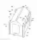
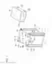
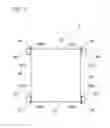
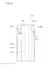
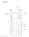
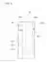
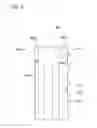
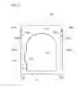
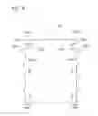
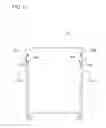
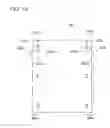
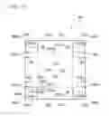
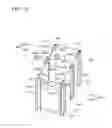
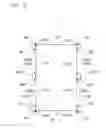
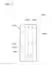
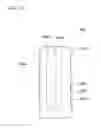
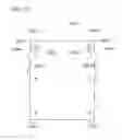
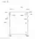
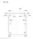
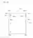
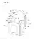
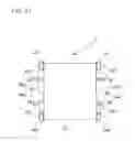
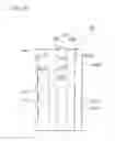
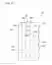
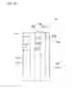
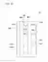
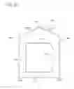
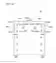
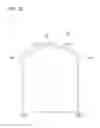
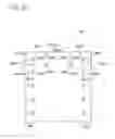
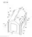
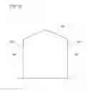
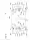
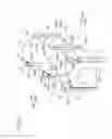
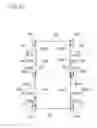
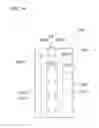
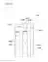
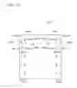

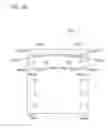
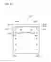
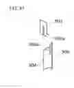
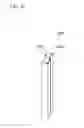
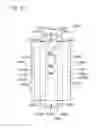
Sources:
- United States Patent and Trademark Office - verify current appl. status at the USPTO↗
Similar patent applications:
- » 20160145852
READY-TO-ASSEMBLE HOUSE
Recent applications in this class:
- » 20230212901 2023-07-06
CONTROL ELEMENTS FOR TRACKING AND MOVEMENT OF FURNITURE AND INTERIOR ARCHITECTURAL ELEMENTS - » 20230160195 2023-05-25
Foldable living compartment - » 20220034080 2022-02-03
Balcony system with counterforce unit - » 20210207359 2021-07-08
MOBILE FACTORY - » 20210180314 2021-06-17
Expandable field kitchen - » 20210140170 2021-05-13
Visual and auditory reducing enclosure - » 20200392722 2020-12-17
Expandable shelter assembly - » 20200332512 2020-10-22
FOLDABLE BUILDING SYSTEM AND METHODS OF USE - » 20200263414 2020-08-20
Foldable building structures with utility channels and laminate enclosures - » 20200256050 2020-08-13
Shipping container expansion insert
Recent applications for this Assignee:
- » 20250143253 2025-05-08
EXCREMENT TREATMENT MATERIAL AND METHOD FOR MANUFACTURING THE SAME - » 20250143252 2025-05-08
EXCREMENT TREATMENT MATERIAL AND METHOD FOR MANUFACTURING THE SAME - » 20250000051 2025-01-02
WATER ABSORPTION TREATMENT MATERIAL AND METHOD FOR MANUFACTURING THE SAME - » 20240381834 2024-11-21
EXCREMENT TREATMENT MATERIAL AND METHOD FOR MANUFACTURING THE SAME - » 20240357992 2024-10-31
ANIMAL TOILET - » 20240251749 2024-08-01
WATER ABSORPTION TREATMENT MATERIAL AND METHOD FOR MANUFACTURING THE SAME - » 20240215530 2024-07-04
ANIMAL TOILET - » 20240188530 2024-06-13
ANIMAL TOILET - » 20240140694 2024-05-02
EXCREMENT TREATMENT MATERIAL AND METHOD FOR MANUFACTURING THE SAME - » 20240040990 2024-02-08
EXCREMENT TREATMENT MATERIAL AND METHOD FOR MANUFACTURING THE SAME