Optical system of a high-resolution imaging spectrograph for deep UV Raman spectroscopy
US20160169741A1
2016-06-16
14/962,100
2015-12-08
✅ Patent granted
US 10,190,912 B2
2019-01-29
-
-
Michael C Bryant
Schmeiser, Olsen & Watts, LLP
2035-12-08
Abstract:
An optical system of a high-resolution imaging spectrograph intended for deep ultraviolet Raman spectroscopy, including an entrance aperture constituted by a slit, followed by a collimating objective, with a dispersive element located between the collimating objective and the subsequent focusing objective is provided. A multichannel radiation detector is arranged behind the focusing objective. The collimating objective is formed at least by a main mirror, wherein the focussing objective is formed by a set of lenses. The dispersion element is formed at least by one diffraction grating 4 and/or an optical prism.
Inventors:
- Josef Kapitán 2 🇨🇿 Sternberk, Czech Republic
- Daniel Vacula 2 🇨🇿 Brest, Czech Republic
- Zdenek Losták 1 🇨🇿 Olomouc, Czech Republic
- Vlastislav Svoboda 1 🇨🇿 Prerov, Czech Republic
- Josef Kapitán 1 🇨🇿 {hacek over (S)}ternberk, Czech Republic
- Daniel Vacula 1 🇨🇿 B{hacek over (r)}est, Czech Republic
- Zden{hacek over (e)}k Lo{hacek over (s)}t'ák 1 🇨🇿 Olomouc, Czech Republic
- Vlastislav Svoboda 1 🇨🇿 P{hacek over (r)}erov, Czech Republic
Assignee:
- MEOPATA—OPTIKA, S.R.O. 1 🇨🇿 Prerov, Czech Republic
- UNIVERZITA PALACKÉHO V OLOMOUC 1 🇨🇿 Olomouc, Czech Republic
Applicant:
Interested in similar patents?
Get notified when new applications in this technology area are published.
Classification:
G01J1/0411 » CPC further
Photometry, e.g. photographic exposure meter; Details; Optical or mechanical part supplementary adjustable parts; Optical elements not provided otherwise, e.g. manifolds, windows, holograms, gratings using focussing or collimating elements, i.e. lenses or mirrors; Aberration correction
G01J1/0414 » CPC further
Photometry, e.g. photographic exposure meter; Details; Optical or mechanical part supplementary adjustable parts; Optical elements not provided otherwise, e.g. manifolds, windows, holograms, gratings using plane or convex mirrors, parallel phase plates, or plane beam-splitters
G01J1/04 IPC
Photometry, e.g. photographic exposure meter; Details Optical or mechanical part supplementary adjustable parts
G01J3/44 » CPC main
Spectrometry; Spectrophotometry; Monochromators; Measuring colours; Investigating the spectrum Raman spectrometry; Scattering spectrometry ; Fluorescence spectrometry
G01J3/28 IPC
Spectrometry; Spectrophotometry; Monochromators; Measuring colours Investigating the spectrum
G01J3/0208 » CPC further
Spectrometry; Spectrophotometry; Monochromators; Measuring colours; Details; Optical elements not provided otherwise, e.g. optical manifolds, diffusers, windows using focussing or collimating elements, e.g. lenses or mirrors; performing aberration correction
G01J3/2823 » CPC further
Spectrometry; Spectrophotometry; Monochromators; Measuring colours; Investigating the spectrum Imaging spectrometer
G01J3/02 IPC
Spectrometry; Spectrophotometry; Monochromators; Measuring colours Details
G01J3/36 » CPC further
Spectrometry; Spectrophotometry; Monochromators; Measuring colours; Investigating the spectrum; Measuring the intensity of spectral lines directly on the spectrum itself Investigating two or more bands of a spectrum by separate detectors
Description
CROSS-REFERENCE TO RELATED APPLICATIONS
This application claims priority to Czech Application No. PV 2014-882, having a filing date of Dec. 10, 2014, the entire contents of which are hereby incorporated by reference.
FIELD OF TECHNOLOGY
The following relates to an arrangement of an optical system of a high lens speed, high-resolution imaging spectrograph to detect the electromagnetic spectrum that is primarily intended for ultraviolet Raman spectroscopy, in particular for identification of substances in determining their composition and structure, and for analysis of surfaces and biological systems.
BACKGROUND
At present, spectrographs containing basic optical elements are mainly used to detect the incident electromagnetic radiation differentiated according to wavelengths, such basic optical elements being: an aperture for the entering polychromatic, usually divergent radiation beam, e.g. a slit. Furthermore, a collimating element which converts the divergent optical beam coming from the entrance aperture into a collimated beam—which is parallel. Further, a dispersive element, generally an element causing refractive dispersion (light refraction) or diffractive dispersion (light diffraction) of a polychromatic beam into monochromatic beams according to wavelengths. Further, it comprises a focusing element, which generates an image of the entrance aperture—usually a slit, at the site of a certain focal plane of the exit aperture, usually on the flat multi-channel radiation detector, in order to record simultaneously the radiation of a large number of wavelengths. The dispersive element in multi-channel detectors is usually a diffraction grating or a dispersive prism.
Notes on Raman spectroscopy: Raman spectroscopy is used to study the structure of Raman scattering molecules. Raman scattering is an inelastic scattering of the optical radiation on the molecules of the test substance, at which the frequency of the scattered radiation is shifted towards the frequency of the incident radiation by a value that corresponds to the rotational or vibrational transition in the molecule. A molecule can exist in states with energy that acquires only certain allowed values or energy levels. Vibrational or rotational transition is a change in the molecular state characterized by an abrupt change in the vibrational and rotational energy levels of the molecule. Vibrational energy level is a possible value of energy that is acquired by a molecule in the vibrational motion of its atoms around their equilibrium position. Rotational energy level is a value of energy that can be acquired by a molecule during its rotational movement around the axis passing through its center of gravity. These energy levels are dependent on the particular atomic structure and their spatial arrangement, i.e. on the type of the test substance.
Raman spectroscopy is used to measure inelastically scattered light (Raman scattering) on the molecules of the test substance. Scattered radiation has a different wavelength than the incident radiation, due to interactions of the radiation with vibrational and in some cases rotational states of molecules. The scattered radiation carries a large amount of information about the nature and structure of the test substance. Resonance enhancement of Raman scattering of biologically relevant substances (proteins, nucleic acids, and others) can be achieved in the ultraviolet region of the spectrum, at about 205 to 270 nm, to obtain additional unique information on these substances.
Raman scattering is a relatively weak phenomenon. The spectrograph for Raman spectroscopy is subject to high demands in terms of lens speed, i.e. the amount of radiation transferred to the detector. Further efforts are needed to achieve high resolution (0.03 to 0.06 nm) and spectral range of tens of nanometers.
The currently used and commercially available spectrographs (supplied by Horiba Jobin Yvon, Princeton Instruments, Andor) useful for Raman scattering in the UV region, are generally composed of two mirrors and a reflective diffraction grating. Alternatively, the optical assembly is complemented by an additional correction mirror, as described for example in the U.S. Patent Publication 2013/0182250 A1. The patent covers the design of mirror imaging spectrographs, in which the assembly of the collimating mirror, diffraction grating and focusing mirror is supplemented by at least one corrective aspheric mirror, which is intended to correct extra-axial imaging defects (aberrations), in particular astigmatism and coma. The advantage of the mirror systems is their achromaticity (absence of color defects) and a relatively high reflectivity. The disadvantages are the limited possibility of correction of other optical defects, in particular astigmatism and coma. Moreover, these spectrographs achieve maximum lens speed of only about f/4.
Better correction of optical defects, and thereby a higher lens speed, can be achieved using lens objectives. In the visible spectral range, these systems with the lens speed of up to f/1.8 and using transmission gratings (supplied by Kaiser, model Holospec f/1.8) are very well available. However, the situation in the ultraviolet spectral region is completely different, mainly due to the limited number of transparent optical materials. There is high demand on the design of lenses, thus increasing the complexity of the system and its cost. The scientific literature describes only one spectrograph operating in the UV spectral region and containing lens objectives as collimating and focusing elements, which achieves the nominal lens speed of f/2. This system, however, achieves spectral resolution of only 12-14 cm−1 and its throughput is limited by surface losses and vignetting (blocking of the outer parts of the beam) due to a large distance between the collimating and focusing objectives.
SUMMARY
An aspect relates to a spectrograph that achieves a higher lens speed (f/2) than the mirror systems, while maintaining high spectral resolution necessary for Raman spectroscopy, and achieving a higher throughput than that of the full lens system. The spectrograph should be applicable for multichannel detectors equipped with a cooled detector chip and a cover glass. It requires the use of a circular pupil of the focusing aspect for the diffracted radiation beam. The system must allow tuning, i.e., a change in the wavelength range by simply rotating the diffraction grating, and a small change in the position and orientation of the detector—focusing into the focusing plane.
The said goal is largely met by the high resolution imaging spectrograph, intended for deep ultraviolet Raman spectroscopy, the optical system of which comprises an entrance aperture formed by a slit, which is followed by a collimating objective, with a dispersive element placed between the collimating objective and the focusing objective, and a multi-channel radiation detector behind the focusing objective. Embodiments of the invention are characterized in that the collimating aspect is formed by at least a main mirror, while the said focusing aspect is formed by a set of lenses. At the same time, the dispersive element is formed by at least one diffraction grating and/or an optical prism.
The optical system of the imaging spectrograph may have a collimating aspect comprising an aspherical mirror and a corrective mirror with an aperture.
In a preferable embodiment, the focusing aspect consists of seven lenses, of which at least one has an aspherical surface.
The higher performance of the spectrograph with an optical system as per embodiments of the invention is that it achieves a higher lens speed (f/2) than the mirror systems, while maintaining high spectral resolution required for Raman spectroscopy. It also achieves a higher throughput than that of the full lens system. The spectrograph can be used with multi-channel detectors equipped with a cooled detector chip and a glass cover. It is advantageous to use the circular pupil of the focusing aspect for the diffracted radiation beam. Embodiments of the invention must allow tuning, e.g., a change in the wavelength range by simply rotating the diffraction grating, and a small change in the position and orientation of the detector—focusing into the focusing plane.
BRIEF DESCRIPTION
Some of the embodiments will be described in detail, with reference to the following figures, wherein like designations denote like members, wherein:
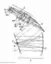
FIG. 1 is an embodiment of the collimating objective formed by a pair of mirrors with a diffraction grating and a seven-lens focusing objective.
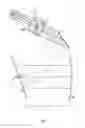
FIG. 2 is a simplified embodiment of the diffraction grating as a dispersive element, wherein the focusing objective is formed by one mirror,
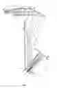
FIG. 3 shows an example of embodiment with a pair of mirrors in the collimating objective and an assembly of five lenses in the focusing objective,
FIG. 4 shows an example of embodiment wherein the dispersion of polychromatic beam is achieved by a dispersive system consisting of a combination of grating and prism.
DETAILED DESCRIPTION
Example 1
Collimating objective 7 of the spectrograph, the optical system of which is shown in FIG. 1, consists of two aspherical mirrors 2, 3, designated as main 2 and corrective 3. The aspherical corrective mirror 3 has an aperture 10 in its center, with size allowing passage of the polychromatic divergent light beam 11 originating from slit 1 without being vignetted at the edges. The focusing objective 8 consists of the assembly 9 of seven lenses 9.1, 9.2, 9.3, 9.4, 9.5, 9.6, 9.7, one of them having an aspherical surface. A combination of fused silica and CaF2 has been selected as the material of the individual optical elements of the focusing objective 8. Diffraction grating 4 with a frequency of 3600 lines/mm is placed between the collimating objective 7 and the focusing objective 8. The diffraction grating 4 uses the first diffraction order, with >40% efficiency. Before hitting the detector 6, the light beam 11 passes through the cover glass 5 which is a part of detector 6. Parameters of the respective optical surfaces are shown below in Table 1.
Aspherical surface is defined by the relation
z = cr 2 1 + 1 - ( 1 + K ) c 2 r 2 + ∑ i A i r i
where c is the surface curvature (the reciprocal value of the radius), K is the conic constant, r is the radial coordinate and Ai are aspherical coefficients.
Parameters of the respective optical media a through q of the optical system according to FIG. 1 are shown in Table 1, where the dimensions are given in mm.
| TABLE 1 |
| Parameters of the spectrograph as per FIG. 1 |
| Example 1 of the invention application |
| (dimensions in mm) |
| area | radius | thickness | material | comments |
| 1 | plane | 200 | air | Slit 1 |
| a | 401.789 | −180 | mirror | Main aspherical mirror 2 |
| K = 0.107497, A4 = −1.572858E−9, | ||||
| A6 = −1.006896E−13, A8 = 1.991723E−17, | ||||
| A10 = −1.855797E−21 | ||||
| b | 93476.4 | 200 | mirror | Correction aspherical mirror 3 |
| K = −4995714, A4 = −2.348767E−9, | ||||
| A6 = −2.497952E−13, A8 = 4.020043E−17, | ||||
| A10 = −3.148018E−21 rotated by 20°; | ||||
| c | plane | 80 | mirror | diffraction grating 4 with frequency of 3600 |
| lines/mm; rotated by −0.7° (for the wavelength | ||||
| range from 250 to 272 nm) | ||||
| the angle between the optical axes of lenses 7, 8 = | ||||
| 68° | ||||
| d | 224.497 | −6.293 | fused silica | lens 9.1 |
| e | 182.502 | −8.242 | air | |
| f | 57.558 | −20.004 | fused silica | lens 9.2 |
| g | −93.609 | −0.296 | air | |
| h | −63.458 | −16.898 | CaF2 | lens 9.3 |
| i | 68.974 | −0.175 | air | |
| j | 107.435 | −10.172 | CaF2 | lens 9.4 |
| k | 97.214 | −6.266 | air | |
| l | 51.565 | −4.987 | fused silica | lens 9.5 |
| m | −41.336 | −0.619 | air | |
| n | −42.117 | −20.034 | CaF2 | lens 9.6 |
| o | 72.268 | −42.402 | air | |
| p | −52.762 | −18.005 | fused silica | Lens 9.7 |
| K = −15.14056, A4 = −9.654539E−6, | ||||
| A6 = 2.199664E−8, A8 = −1.537923E−11 | ||||
| q | −28.218 | −8.772 | air | |
| r | plane | −1 | fused silica | cover glass 5 |
| s | plane | −9 | air | |
| image | plane | detector 6 | ||
| *Where K denotes conicity and Ai other aspheric coefficients |
Example 2
The collimating objective 7 of the spectrograph, the optical system of which is shown in FIG. 2, unlike the previous embodiment example, consists of the off-axis, biconic, aspherical mirror 2. The focusing objective 8 consists of seven lenses 9.1, 9.2, 9.3, 9.4, 9.5, 9.6, and 9.7. A combination of fused silica and CaF2 has been selected as the material of the individual optical elements of the focusing objective 8. Diffraction grating 4 with a frequency of 3600 lines/mm is placed between the collimating objective 7 and the focusing objective 8. The diffraction grating 4 uses the first diffraction order, with >40% efficiency. The polychromatic divergent light beam coming out of the slit 1 falls on the collimating objective 7 consisting of one main mirror 2 and is reflected to the diffraction grating 4. Diffraction of the light beam occurs on the diffraction grating 4 dispersing the polychromatic beam due to the effects of light diffraction on the grating 4. Before hitting the detector 5, the light beam may or may not pass through the cover glass 4 which is a part of detector 6. Parameters of the respective optical surfaces in this particular embodiment are specified below in Table 2.
| TABLE 2 |
| Parameters of the spectrograph as per FIG. 2 |
| Example 2 of the invention application |
| (dimensions in mm) |
| area | radius | thickness | material | comments |
| object | plane | 200 | air | Slit 1 |
| a | * | −190 | Mirror | Mirror 2 biconic surface |
| * . . . radius r1 = −400.023; K1 = −0.999427 radius | ||||
| r2 (perpendicular to r1) = −400.370; | ||||
| K2 = −0.998466 | ||||
| b | plane | 80 | mirror | diffraction grating 4 with a frequency of 3600 |
| lines/mm | ||||
| rotated by −6.88° (for the wavelength range from | ||||
| 205 to 220 nm) | ||||
| the angle between the beam incident on the | ||||
| diffraction grating 4 and the optical axis of the | ||||
| focusing objective 8 is 68 degrees | ||||
| c | 77.288 | 5.977 | fused silica | lens 9.1 |
| d | 233.929 | 7.676 | air | |
| e | −84.931 | 20.012 | fused silica | lens 9.2 |
| f | 64.985 | 1.869 | air | |
| g | 54.381 | 25.005 | CaF2 | lens 9.3 |
| h | −85.406 | 0.181 | air | |
| i | 115.500 | 10.081 | CaF2 | lens 9.4 |
| j | −93.643 | 5.606 | air | |
| k | −54.296 | 15.016 | fused silica | lens 9.5 |
| l | 42.624 | 3.859 | air | |
| m | 49.866 | 20.015 | CaF2 | lens 9.6 |
| n | −76.024 | 45.024 | air | |
| o | 34.906 | 18.024 | fused silica | lens 9.7 |
| p | 26.760 | 10.022 | air | |
| q | plane | 1 | fused silica | cover glass 5 |
| r | plane | 9 | air | |
| image | plane | detector 6 | ||
| * Where Ki denotes conicity |
The beam incident on the focusing objective 8 has a circular cross section, while the beam coming out of the collimating objective 7 and incident on the diffraction grating 4 has an elliptical cross section.
Example 3
The embodiment example 3 differs from example 1 in that the focusing objective 8 is composed of five lenses 9.1, 9.2, 9.3, 9.4 and 9.5.
Collimating objective 7 of the spectrograph, the optical system of which is shown in FIG. 3, consists of two aspherical mirrors 2, 3, which are designated as main mirror 3 and corrective mirror 2. The aspherical corrective mirror 3 has an aperture 10 in its center, with size allowing passage of the polychromatic divergent light beam coming out of the slit 1, without being vignetted at the edges. The focusing objective 8 is composed of five lenses 9.1, 9.2, 93, 9A, and 9.5, three of them having aspherical surfaces. A combination of fused silica and CaF2 has been selected as the material of the individual optical elements of the focusing objective 8. Diffraction grating 4 with a frequency of 3600 lines/mm is placed between the collimating objective 7 and the focusing objective 8. The grating 4 uses the first diffraction order, with >40% efficiency. Before hitting detector 6, the light beam may pass through the cover glass 5, which is a part of detector 6. Parameters of the respective optical surfaces are shown below in Table 3. Aspherical surface is defined by the relation (A). Parameters of the respective optical media a through o of the optical system according to FIG. 2 are shown in Table 2, where the dimensions are given in mm.
| TABLE 3 |
| Parameters of example 3 of the spectrograph embodiment: |
| Example 3 of the invention application |
| (dimensions in mm) |
| area | radius | thickness | material | comments |
| object | plane | 200 | air | Slit 4 |
| a | −401.79 | −180 | mirror | Main mirror 2, * K = 0.107491, A4 = −1.572926E−9, |
| A6 = −1.006967E−13, A8 = 1.991713E−17, | ||||
| A10 = −1.844422E−21 | ||||
| b | 93664.6 | 200 | mirror | Correction mirror 3, rotated by 20 degrees; |
| K = −4995723, A4 = −2.342046E−9, A6 = −2.501973E−13 | ||||
| A8 = 4.018759E−17 A10 = −3.162602E−21 | ||||
| c | plane | −80 | mirror | diffraction grating 4 with the frequency of 3600 |
| lines/mm; rotated by −2.7° (for the wavelength | ||||
| range from 218 to 234 nm) | ||||
| the angle between the beam incident on the | ||||
| diffraction grating 4 and the optical axis of the | ||||
| focusing objective 8 is 68 degrees | ||||
| d | −72.079 | −3.000 | fused silica | lens 9.1 |
| e | −41.655 | −1.000 | air | |
| f | −36.205 | −18.125 | fused silica | lens 9.2 |
| K = −0.011368, A4 = 3.305605E−7, | ||||
| A6 = 2.311898E−9, A8 = −7.310637E−13 | ||||
| g | 70.164 | −4.099 | air | |
| h | 54.186 | −3.275 | CaF2 | lens 9.3 |
| i | −37.146 | −0.498 | air | |
| j | −37.695 | −20.002 | CaF2 | lens 9.4 |
| k | 75.983 | −39.398 | air | K = −0.619901, A4 = 7.664860E−7, |
| A6 = 2.173671E−9, A8 = −3.028988E−12 | ||||
| l | −59.329 | −20.000 | fused silica | lens 9.5 |
| K = −2.313735, A4 = 4.698205E−7, | ||||
| A6 = 1.901152E−8, A8 = −2.225080E−11 | ||||
| m | −36.803 | −10.314 | air | |
| n | plane | −1 | fused silica | cover glass 5 |
| o | plane | −9 | air | |
| image | plane | detector 6 | ||
| * Where K denotes conicity and Ai other aspheric coefficients |
Example 4
Embodiment example 4, according to FIG. 4, is different compared to the embodiment 1 in that it comprises in addition a dispersive prism 41 in the optical assembly. The optical prism 41 has two functions: it increases the spectral resolution by increasing the total dispersion of the system, and it compensates for beam expansion (anamorphic reduction) on the diffraction grating 4, so that the collimated beam incident on and coming out of the system of dispersive elements 41, 4 has about a circular cross section.
Collimating objective 7 of the spectrograph, the optical system of which is shown in FIG. 4, consists of two aspherical mirrors 2, 3, which are designated as main mirror 3 and corrective mirror 2. The aspherical corrective mirror 3 has an aperture 10 in its center, with size allowing passage of the polychromatic divergent light beam coming out of the slit 1, without being vignetted at the edges. The focusing objective 8 consists of the set of seven lenses 9.1, 9.2, 9.3, 9.4, 9.5, 9.6, and 9.7, one of them having an aspherical surface. A combination of fused silica and CaF2 has been selected as the material of the individual optical elements of the focusing objective 8. A combination of prism 41 and diffraction grating 4 with a frequency of 3600 lines/mm is placed as a dispersive element between the collimating objective and the focusing objective. The grating 4 uses the first diffraction order, with >40% efficiency. Before hitting detector 7, the light beam may pass through the cover glass 5 which is a part of detector 6. Parameters of the respective optical surfaces are shown below in Table 4.
Aspherical surface is defined by the relation
z = cr 2 1 + 1 - ( 1 + K ) c 2 r 2 + ∑ i A i r i
Parameters of the respective optical media a through u of the optical system according to FIG. 4 are shown in Table 4, where the dimensions are given in mm.
| TABLE 4 |
| Parameters of example 4 of the spectrograph embodiment: |
| Example 4 of the invention application |
| (dimensions in mm) |
| area | radius | thickness | material | comments |
| object | plane | 200 | air | Slit 4 |
| a | −401.79 | −180 | mirror | Main mirror 2, K = 0.107491, A4 = − 1.572926E−9, |
| A6 = −1.006967E−13, A8 = 1.991713E−17, | ||||
| A10 = −1.844422E−21 | ||||
| b | 93664.6 | 300 | mirror | Correction mirror 3, rotated by 20 degrees; |
| K = −4995723, A4 = −2.342046E−9, A6 = −2.501973E−13 | ||||
| A8 = 4.018759E−17 A10 = −3.162602E−21 | ||||
| c | plane | 35 * | fused silica | Prism 41, - Angle of rotation 56.38°. |
| Apex angle of 18°. | ||||
| d | plane | 169.26 | air | |
| e | plane | −90 | mirror | diffraction grating 4 with the frequency of 3600 |
| lines/mm; rotated by −3.5° (for the wavelength | ||||
| range from 218 to 234 nm) | ||||
| the angle between the beam incident on the | ||||
| diffraction grating 4 and the optical axis of the | ||||
| focusing objective 8 is 68 degrees | ||||
| f | — | −9.511 | fused | Lens 9.1 |
| 224.724 | silica | |||
| g | 182.405 | −9.187 | air | |
| h | 57.466 | −18.616 | fused silica | lens 9.2 |
| i | −94.675 | −0.515 | air | |
| j | −63.907 | −16.996 | CaF2 | lens 9.3 |
| k | 68.392 | −0.158 | air | |
| l | 108.433 | −10.276 | CaF2 | lens 9.4 |
| m | 95.827 | −6.298 | air | |
| n | 51.242 | −6.647 | fused silica | lens 9.5 |
| o | −41.349 | −0.977 | air | |
| p | −42.500 | −20.147 | CaF2 | lens 9.6 |
| q | 71.780 | −42.226 | air | |
| r | −56.418 | −17.998 | fused silica | lens 9.7 |
| K = −15.31897, A4 = −7.803339E−6, | ||||
| A6 = 1.732514E−8, A8 = −1.043447E−11 | ||||
| s | −31.282 | −8.077 | air | |
| t | plane | −1 | fused silica | cover glass 5 |
| u | plane | −9 | air | |
| image | plane | detector 6 | ||
| * Where K denotes conicity and Ai other aspheric coefficients |
Other parameters common to all embodiment examples:
Lens speed of the spectrograph: at least f/2
The focal length of the focusing objective 8: 100 mm
Resolution of lenses 7, 8: 40 lines per mm
The absolute value of magnification of the optical system: 0.5×
The spectrograph is intended for multichannel cooled detectors 6 with the following parameters:
-
- the size of the visible field at least 15×6 mm
- pixel size: 13×13 um to 26×26 um
- cover glass 5 of fused silica with thickness 0-1.5 mm
The spectral resolution of the spectrograph is dependent on the selected spectral range (excitation wavelength), and is shown in Table 5 for the aforementioned embodiment example 1:
| TABLE 5 |
| Spectral resolution for the various spectrograph configurations |
| Wavelength | Angle | ||
| excitation | rotation of | ||
| length | grating 4 | Spectral resolution (cm−1) |
| Config. | (nm) | (deg) | 500 cm−1 | 1800 cm−1 | 3200 cm−1 |
| 1 | 250 | −0.7 | 8.9 | 7.1 | 4.4 |
| 2 | 240 | 1.0 | 9.9 | 8.2 | 5.7 |
| 3 | 230 | 2.7 | 11.3 | 9.4 | 7.0 |
| 4 | 218 | 4.4 | 13.0 | 11.0 | 9.0 |
| 5 | 205 | 6.5 | 14.9 | 13.3 | 11.3 |
Embodiments of the invention need not be limited to these examples. In practice, values of the individual parameters of the focusing objective 8 may range in the following intervals:
| TABLE 6 |
| Possible range of parameters for the focusing objective 8 |
| Range of parameters for the focusing objective 8 |
| (dimensions in mm) |
| radius | thickness | material | comments |
| −210 ÷ −230 (convex) | −5 ÷ −10 | fused silica | lens 9.1 |
| 180 ÷ 190 (convex) | −7 ÷ −10 | air | |
| 55 ÷ 58 (concave) | −7 ÷ −20 | fused silica | lens 9.2 |
| −90 ÷ −100 (concave) | −0.25 ÷ −0.5 | air | |
| −60 ÷ −65 (convex) | −15 ÷ −20 | CaF2 | lens 9.3 |
| 65 ÷ 75 (convex) | −0.15 ÷ 0.2 | air | |
| −100 ÷ −110 (convex) | −10 ÷ −12 | CaF2 | lens 9.4 |
| 80 ÷ 100 (convex) | −4 ÷ −7 | air | |
| 50 ÷ 55 (concave) | −5 ÷ −15 | fused silica | lens 9.5 |
| −35 ÷ −45 (concave) | −0.5 ÷ −2 | air | |
| −40 ÷ −45 (convex) | −20 ÷ −25 | CaF2 | lens 9.6 |
| 70 ÷ 75 (convex) | −35 ÷ −45 | air | |
| 50 ÷ 65 (convex) | −17 ÷ −19 | fused silica | lens 9.7 |
| K = −15 ÷ −20 | |||
| A4 = −6 ÷ −10E−6 | |||
| A6 = 1.5 ÷ 2.5E−8 | |||
| A8 = −1 ÷ −1.6E−11 | |||
| −25 ÷ −35 (concave) | −7 ÷ −10 | air | |
| Where K denotes conicity and Ai other aspheric coefficients |
The function of the optical system according to embodiments of the invention, i.e. the spectrograph function according to examples 1 and 3 is as follows:
The polychromatic divergent light beam enters into the spectrograph system through the slit 1, passes through the aperture 10 in the aspherical correction mirror 3 and falls on the main correction mirror 2, from which it is reflected. Given the shape of the main correction mirror 2 and the fact that the slit 1 is close to its focal point, the divergent beam becomes almost collimated after the reflection. The beam continues to the aspherical correction mirror 3, from which it is also reflected, and due to the influence of the aspherical surface, the beam becomes even more collimated. The collimated beam then falls on the reflective diffraction grating 4. Upon incidence on the grating 4 the light beam is diffracted and the polychromatic beam is diffracted on the grating 4 to the respective monochromatic beams which are then further spread under different angles corresponding to their wavelengths. These beams pass through the seven-lens focusing objective 8, which is intended to focus the beams onto the detector 6. Before hitting detector 6 the beams pass through the glass cover 5, which serves as a protection of detector 6.
INDUSTRIAL APPLICABILITY
The embodiments of the invention can be applied in high-resolution imaging spectrographs for deep UV Raman spectroscopy. Spectrographs with the applied invention can be produced in an industrial scale.
Claims
1. A high resolution optical system of the imaging spectrograph to detect the spectrum of electromagnetic radiation in the UV region, intended for deep ultraviolet Raman spectroscopy, comprising an entrance aperture formed by a slit, which is followed by a collimating optical assembly, with a dispersive element inserted between it and the following focusing objective, and with a multi-channel radiation detector arranged behind the focusing objective, wherein the collimating objective comprises at least a main mirror, wherein the focussing objective is formed by a set of lenses, and the dispersive element is formed by at least one diffraction grating 4 and/or an optical prism.
2. The optical system of the imaging spectrograph as per claim 1, wherein the collimating objective comprises an aspherical mirror and a correction mirror with an opening.
3. The optical system of the imaging spectrograph as per claim 1, wherein the focusing objective (8) comprises seven lenses, of which at least one has an aspherical surface.
4. The optical system of the imaging spectrograph as per claim 1, wherein the focusing objective has the following parameters:
| Radius (mm) | Thickness (mm) | material | element |
| −210 ÷ −230 (convex) | −5 ÷ −10 | fused silica | lens 9.1 |
| 180 ÷ 190 (convex) | −7 ÷ −10 | air | |
| 55 ÷ 58 (concave) | −7 ÷ −20 | fused silica | lens 9.2 |
| −90 ÷ −100 (concave) | −0.25 ÷ −0.5 | air | |
| −60 ÷ −65 (convex) | −15 ÷ −20 | CaF2 | lens 9.3 |
| 65 ÷ 75 (convex) | −0.15 ÷ 0.2 | air | |
| −100 ÷ −110 (convex) | −10 ÷ −12 | CaF2 | lens 9.4 |
| 80 ÷ 100 (convex) | −4 ÷ −7 | air | |
| 50 ÷ 55 (concave) | −5 ÷ −15 | fused silica | lens 9.5 |
| −35 ÷ −45 (concave) | −0.5 ÷ −2 | air | |
| −40 ÷ −45 (convex) | −20 ÷ −25 | CaF2 | lens 9.6 |
| 70 ÷ 75 (convex) | −35 ÷ −45 | air | |
| 50 ÷ 65 (convex) | −17 ÷ −19 | fused silica | lens 9.7 |
| K = −15 ÷ −20 | |||
| A4 = −6 ÷ −10E−6 | |||
| A6 = 1.5 ÷ 2.5E−8 | |||
| A8 = −1 ÷ −1.6E−11 | |||
| −25 ÷ −35 (concave) | −7 ÷ −10 | air | |
| Where K denotes conicity and Ai other aspheric coefficients |
Images & Drawings included:


Sources:
- United States Patent and Trademark Office - verify current appl. status at the USPTO↗
Recent applications in this class:
- » 20250258039 2025-08-14
SPECTROSCOPY DEVICE, RAMAN SPECTROSCOPIC MEASUREMENT DEVICE, AND SPECTROSCOPY METHOD - » 20250244174 2025-07-31
RAMAN SPECTROSCOPY METHOD WITH SINGLE-CHANNEL DETECTION WITHOUT A DISPERSION ELEMENT, AND DEVICE FOR IMPLEMENTING THE METHOD - » 20250146872 2025-05-08
SYSTEM AND METHOD FOR TEMPERATURE PROFILING WITH RAMAN SCATTERING - » 20250035487 2025-01-30
CHIRP MODULATION SIMULATED RAMAN SCATTERING MICROSCOPY - » 20240393179 2024-11-28
SYSTEM AND METHOD FOR SPECTROSCOPIC DETERMINATION OF INTENSITY LEVEL AND SIGNAL-TO-NOISE RATIO FROM SAMPLE SCANS - » 20240230407 2024-07-11
APPARATUSES, SYSTEMS, AND METHODS FOR DETECTING MATERIALS BASED ON RAMAN SPECTROSCOPY - » 20240219236 2024-07-04
RAMAN SPECTROSCOPY DEVICE AND RAMAN SPECTROSCOPY MEASUREMENT METHOD - » 20240175752 2024-05-30
Systems and Methods for Compact and Low-Cost Vibrational Spectroscopy Platforms - » 20240175751 2024-05-30
INFRARED RAMAN DEVICE - » 20240133739 2024-04-25
Apparatuses, systems, and methods for detecting materials based on Raman spectroscopy