Electric damper for a motor vehicle
US20160172956A1
2016-06-16
14/436,751
2013-09-20
✅ Patent granted
US 9,397,545 B2
2016-07-19
WO; PCT/EP2013/002834; 20130920
WO; WO2014/060062; 20140424
Faye M Fleming
Henry M. Feiereisen LLC
2033-09-20
Abstract:
An electric damper for a motor vehicle for damping a relative movement between two components includes an electric generator for generating an induction voltage, the generator being drivable by the relative movement and having a rotor and a stator. The rotor includes a rotor shaft that is rotationally coupled to at least one rotor disk. A field-generating ring is provided in which elements that can be magnetized in segments are connected to the field-generating means such that the magnetizable elements are polarized alternately over the periphery of the ring. At least one coil ring with coil windings is provided which are arranged in segments, the coil ring and the field-generating ring being concentrically arranged.
Assignee:
- AUDI AG 3,213 🇩🇪 INGOLSTADT, Germany
Applicant:
Interested in similar patents?
Get notified when new applications in this technology area are published.
Classification:
F16F15/035 » CPC further
Suppression of vibrations in systems ; Means or arrangements for avoiding or reducing out-of-balance forces, e.g. due to motion; Suppression of vibrations of non-rotating, e.g. reciprocating systems; Suppression of vibrations of rotating systems by use of members not moving with the rotating systems using magnetic or electromagnetic means by use of eddy or induced-current damping
F16F9/12 » CPC further
Springs, vibration-dampers, shock-absorbers, or similarly-constructed movement-dampers using a fluid or the equivalent as damping medium using liquid only; using a fluid of which the nature is immaterial Devices with one or more rotary vanes turning in the fluid any throttling effect being immaterial, i.e. damping by viscous shear effect only
H02K49/10 » CPC main
Dynamo-electric clutches; Dynamo-electric brakes of the permanent-magnet type
B60G17/015 IPC
Resilient suspensions having means for adjusting the spring or vibration-damper characteristics, for regulating the distance between a supporting surface and a sprung part of vehicle or for locking suspension during use to meet varying vehicular or surface conditions, e.g. due to speed or load the regulating means comprising electric or electronic elements
B60G13/08 » CPC further
Resilient suspensions characterised by arrangement, location or type of vibration dampers having dampers dissipating energy, e.g. frictionally of fluid type hydraulic
B60G17/0157 » CPC further
Resilient suspensions having means for adjusting the spring or vibration-damper characteristics, for regulating the distance between a supporting surface and a sprung part of vehicle or for locking suspension during use to meet varying vehicular or surface conditions, e.g. due to speed or load the regulating means comprising electric or electronic elements characterised by the action on a particular type of suspension unit non-fluid unit, e.g. electric motor
F16F15/03 IPC
Suppression of vibrations in systems ; Means or arrangements for avoiding or reducing out-of-balance forces, e.g. due to motion; Suppression of vibrations of non-rotating, e.g. reciprocating systems; Suppression of vibrations of rotating systems by use of members not moving with the rotating systems using magnetic or electromagnetic means
Description
The invention relates to an electric damper for motor vehicle portending the relative movement between two components according to the preamble of claim 1.
DE 10 2010 035 084 A1 describes an electric damper for a motor vehicle, which damps the relative movement between two components. The electric damper has a housing, wherein a stator is fixed in the housing. A rotor is arranged rotatable relative to the stator, which has field magnets or induction windings. The rotation of the rotor relative to the state or induces a voltage in the induction windings, which decelerates and thereby damps the rotor. The proposed solution in DE 10 2010 035 084 A1 has the disadvantage that for generating a sufficient damping force a high relative speed between the rotor and the stator is required.
In the above reference this problem is solved by providing a transmission between the articulately connected component and the generator. However, using a transmission only allows increasing the rotational speed or the relative speed of the rotation of the rotor only to a limited degree.
It is an object of the invention to set forth an electric damper for a motor vehicle, which can achieve a sufficient damping also at small excitation amplitudes and a small damper speed.
The object is solved in that the stator has at least two coil rings on which coil windings are segmentally arranged.
The generator also has a stator and a rotor having a rotor shaft, which is fixedly connected with at least one rotor disk.
According to the invention at least one field generating ring of magnetizable elements, in particular a ferromagnetic element, is provided wherein the magnetizable elements are arranged in segments and the elements are connected with a respective end with a field generating means. The north-south orientation of the field generating means is orthogonal to the rotor shaft. The polarity with which the magnetizable elements are provided is selected so that adjoining segments have a different polarity. Further a coil ring is provided which has segmentally circumferential coil windings. The coil ring and the field generating ring are arranged concentric.
In a third embodiment at least two coil rings can be provided, which are arranged concentric relative to the rotor shaft and the ring-shaped arranged field generating means. The coil rings have segmentally circumferential coil windings. The radius of the field generating ring is between the coil circular radii of the two coil rings.
In this way the field generating ring protrudes in axial direction between the two coil rings.
A relative movement between the stator and the rotor results in a relative movement between the field generating ring and the coil rings.
This arrangement causes induction of a voltage in both neighboring coil rings upon rotation of the rotor disk, which in turn generates a magnetic field, which counteracts the rotation of the rotor and thus damps its movement. Due to the simultaneous induction of two coil rings the effective filed change is significantly increased compared to the state-of-the-art.
Further, the coil rings can be arranged on the stator and the magnetizable elements can be arranged on at least one concentric circular circumference on the rotor disk. Further, field generating means are arranged on the rotor disk. They are arranged so that in particular magnetizable elements that oppose each other in radial direction have a different polarity. This can advantageously be achieved by the connection of the magnetizable elements with a respective pole of a field generating means. This allows reducing the number of field generating means. The magnetizable elements can be ferromagnetic elements. Preferably the magnetizable elements are soft magnetic.
Preferably the field generating means radii are situated in radial direction between the coil ring radii.
In a further advantageous embodiment of the invention, at least two field generating rings are provided, which are arranged between three coil rings.
Upon rotation of the coil rings relative to the field generating rings the magnetic field generated by the two neighboring field generating rings acts on the radially intermediate coil ring in the same direction and in this way acts as serial connection.
As a result the damping efficiency is increased while maintaining a compact construction. In a further advantageous embodiment, the field generating means are configured as permanent magnets.
In a further advantageous embodiment of the invention the coil windings of the coil rings are connected with a resistor. Via this resistor a damping can be set. Via a variable resistor this damping can be adjusted in a simple manner. The energy obtained from the damper can advantageously be further used in the vehicle.
A further aspect of the invention relates to a chassis including a chassis control arm and a vehicle superstructure, which are connected to each other by the electric damper described above.
According to an advantageous embodiment, the stator is connected with its housing to the chassis control arm, wherein the rotor shaft, which preferably protrudes on both sides of the stator, is fixedly connected on both sides to a vehicle superstructure. The stator housing can be selected so that it is ideally adjusted to the shape of the control arm eye, thereby causing the movement of the control arm to result in a relative movement between the stator and the rotor shaft. As a result a movement of the chassis control arm relative to the vehicle superstructure is effectively damped.
Further advantages, features and possible applications of the present invention will become apparent from the following description in connection with the exemplary embodiments shown in the drawings.
In the description, in the claims and in the drawing the terms and associated reference signs listed in the list of reference signs below are used. In the drawing it is shown in:
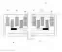
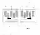
FIG. 1 a schematic view of an electric damper in a first sectional view;
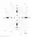
FIG. 2 a schematic view in a second sectional view, and
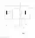
FIG. 3 an arrangement of a generator according to the invention in a vehicle.
FIG. 1 shows a schematic representation of an electric damper 10 with a housing 12 and a rotor 20, which has a rotor shaft 22 and a rotor disk 24. The rotor 20 is rotatably supported in the housing 12. On the housing 12 a first coil ring 14, a second coil ring 16 and a third coil ring 18 are arranged. The coil rings 14, 16, 18 are arranged concentric relative to the rotor shaft 22 and have different radii. The coil rings 14, 16, 18 are configured so that coil windings 14a, 14b, 14d are introduced segmentally in a ring as symbolically shown in FIG. 2.
In addition the electric damper 10 has soft magnetic rings 26, 28. The soft magnetic rings 26, 28 are configured so that soft magnetic elements 26a, 26b, 26c, 26d are segmentally circumferentially arranged. The two radially neighboring soft magnetic elements are connected with permanent magnets 27 which are introduced in the rotor 20. Because the north-south-orientation of the permanent magnets is orthogonal to the rotor shaft 22, the soft magnets 26a, 26b, 26c, 26d are positioned so that their north-south-orientation is orthogonal to the rotor shaft 22, 52. As a result the connected soft magnets 26a, 26b, 26c, 26d are arranged circumferentially with alternating polarity. This is shown in more detail in FIG. 2. As a result of the rotation of the rotor shaft 22, 52 relative to the housing 12 and the coil rings 14, 16, 18 connected to the housing, a voltage is induced in the coil rings 14, 16, 18, thereby decelerating the rotor 20 and damping the movement of the connected components. By guiding a magnet ring 26, 28 between two coil rings a high degree of damping can be provided while requiring only a small number of permanent magnets.
FIG. 2 shows a schematic view of a sectional view.
The concentric arrangement of the coil rings 14, 16, 18 and soft magnet rings 26, 28 about the rotor shaft 22 can be recognized well. In this exemplary embodiment the four coils 14a, 14b, 14c, 14d are arranged in the inner coil ring 14, wherein the individual coils are here shown symbolically. As can be seen in FIG. 1 the cons of the coil rings 14, 16, 8 are connected with the housing 12. The soft magnets 26a, 26b, 26c, 26d are arranged on the rotor disk 24 so as to be rotatable relative to the housing 12. The permanent magnets 27a, 27b, 27c, 27d and the soft magnets 26a, 26b, 26c, 26d are arranged on the soft magnet ring 26 so that their magnetic orientation is orthogonal in radial direction relative to the rotor shaft 22 and their polarity alternates in subsequent segments. The above description regarding the coil ring 14 and the magnet ring 26 also applies to the further outwardly situated coil rings 16, 18 and the soft magnet ring 28. As a result of the arrangement according to the invention high damping values can be achieved by using a small number of permanent magnets also at low rotational speeds. This ensures a cost-effective production of electric dampers.
FIG. 3 shows the top view onto the coil disk 18 in which the coils 30 are circumferentially arranged in segments. In these coils a voltage is induced when the rotor rotates relative to the stator. The segment size for arranging the coils corresponds to the one of the permanent magnets. The number can be selected depending on the application.
LIST OF REFERENCE SIGNS
- 10 electric damper
- 12 housing
- 14 coil ring
- 14a coil winding
- 14b coil winding
- 14c coil winding
- 14d coil winding
- 16 coil ring
- 18 coil ring
- 20 rotor
- 22 rotor shaft
- 24 rotor disk
- 26 soft magnet ring
- 26a permanent magnet
- 26b permanent magnet
- 26c permanent magnet
- 26d permanent magnet
- 27a permanent magnet
- 27b permanent magnet
- 27c permanent magnet
- 27d permanent magnet
- 28 magnet ring
- 30 coil
- 50 generator
- 52 rotor shaft
- 54 vehicle superstructure
- 56 coupling element
- 58 stator
Claims
What is claimed is:1.-7. (canceled)
8. An electric damper for a motor vehicle for damping a relative movement between two components comprising:
an electric generator having a rotor and a stator and being drivable by the relative movement for generating an induction voltage, said rotor having a rotor shaft connected in rotative fixed relationship with at least one rotor disk;
a field generating ring having magnetizable elements provided segmentally in the field generating ring, said magnetizable elements being connected with field generating means so that the magnetizable elements are circumferentially polarized alternately over a periphery of the field generating ring; and
at least one coil ring having segmentally arranged coil windings said at least one coil ring and said field generating ring being arranged concentrically.
9. The electric damper of claim 8, wherein two said coil rings are provided, wherein a radius of the field generating ring is situated between radii of the two coil rings, and wherein a relative movement between the rotor and the stator results in a relative movement between the field generating ring and the coil rings.
10. The electric damper of claim 8, wherein the rotor disc carries the field generating means ring.
11. The electric damper of claim 8, comprising at least two said field generating rings arranged concentrically and connected with the rotor shaft in rotative fixed relationship, wherein the field generating means are arranged so that radially adjacent magnetizable elements have respective different polarities.
12. The electric damper of claim 8, wherein the magnetizable element is a magnetizable element of a first field generating ring.
13. The electric damper of claim 8, wherein the field generating means are configured as permanent magnets.
14. The electric damper of claim 8, wherein the connections of the coil windings of the coil disk are connected to a resistor.
15. A chassis, comprising a chassis control arm, a vehicle superstructure and the electric damper of claim 8, wherein the stator is connected with a chassis control arm and the rotor shaft with a vehicle superstructure.
Images & Drawings included:
Sources:
- United States Patent and Trademark Office - verify current appl. status at the USPTO↗
Similar patent applications:
Recent applications in this class:
- » 20250062670 2025-02-20
INTERACTION FORCE CONTROL DEVICE, ELECTROMAGNETIC BRAKE INCLUDING THE SAME, AND ROTARY ELECTRIC MACHINE INCLUDING THE SAME - » 20240380299 2024-11-14
Torque augmentation apparatus - » 20240079944 2024-03-07
POWER TRANSMISSION STRUCTURE - » 20220294327 2022-09-15
Magnetic coupler with force balancing - » 20200244154 2020-07-30
Magnetic coupler with force balancing - » 20200212789 2020-07-02
Dynamically Induced and Reactive Magnetic Hysteresis Applications and Methods - » 20160197544 2016-07-07
Halbach array and magnetic suspension damper using same - » 20150048702 2015-02-19
NON-CONTACT TYPE POWER GENERATOR - » 20140225467 2014-08-14
MAGNETIC GEAR MECHANISM WITH COILS AROUND PERMANENTLY EXCITED MAGNET POLES - » 20140070632 2014-03-13
Magnetic Flux Drive
Recent applications for this Assignee:
- » 20250282283 2025-09-11
MOTOR VEHICLE WITH PROJECTION SYSTEM - » 20250282174 2025-09-11
WHEEL CARRIER ARRANGEMENT FOR A MOTOR VEHICLE AND METHOD FOR PRODUCING SUCH A WHEEL CARRIER ARRANGEMENT - » 20250276569 2025-09-04
PLASTIC COMPONENT, IN PARTICULAR UNDERRIDE GUARD, HAVING FIRE-RESISTANT TEXTILE FOR AN AT LEAST PARTIALLY ELECTRICALLY DRIVEN MOTOR VEHICLE - » 20250266569 2025-08-21
BATTERY ARRANGEMENT WITH A FIRE PROTECTION ELEMENT BETWEEN A BATTERY MODULE AND A HOUSING COMPONENT, AND METHOD FOR PRODUCING A FIRE PROTECTION ELEMENT - » 20250262935 2025-08-21
DISPLAY SYSTEM - » 20250261031 2025-08-14
METHOD AND SYSTEM FOR TRANSMITTING DATA PACKETS - » 20250260122 2025-08-14
BATTERY SYSTEM AND MOTOR VEHICLE - » 20250260120 2025-08-14
BATTERY CELL FOR A HIGH-VOLTAGE BATTERY AND MOTOR VEHICLE - » 20250260091 2025-08-14
METHOD FOR PRODUCING AN INTER-CELL COOLING UNIT, INTER-CELL COOLING UNIT AND BATTERY FOR A MOTOR VEHICLE - » 20250246746 2025-07-31
CELL SEPARATING ELEMENT, BATTERY MODULE, BATTERY FOR A MOTOR VEHICLE AND METHOD FOR PRODUCING A CELL SEPARATING ELEMENT WITH IMPROVED FIRE PROTECTION AND ADAPTATION PROPERTIES