Pico test leak
US20160195448A1
2016-07-07
14/911,872
2014-08-13
✅ Patent granted
US 9,933,325 B2
2018-04-03
WO; PCT/EP2014/067309; 20140813
WO; WO2015/024831; 20150226
Clayton E Laballe | Kevin Butler
The Webb Law Firm
2034-10-24
Abstract:
A test leak device (10) comprising a gas-filled container (12) and a capillary (18) extending through the container wall is characterized in that the gas consists to at least 10% of atmospheric air (20).
Assignee:
- INFICON GmbH 54 🇩🇪 Cologne, Germany
Applicant:
Interested in similar patents?
Get notified when new applications in this technology area are published.
Classification:
G01M3/007 » CPC main
Investigating fluid-tightness of structures Leak detector calibration, standard leaks
G01M3/00 IPC
Investigating fluid-tightness of structures
G01N33/0006 » CPC further
Investigating or analysing materials by specific methods not covered by groups -; Gaseous mixtures, e.g. polluted air Calibrating gas analysers
G01M3/207 » CPC further
Investigating fluid-tightness of structures by using fluid or vacuum by detecting the presence of fluid at the leakage point using special tracer materials, e.g. dye, fluorescent material, radioactive material calibration arrangements
F02D41/1495 » CPC further
Electrical control of supply of combustible mixture or its constituents; Circuit arrangements for generating control signals; Introducing closed-loop corrections using means for determining characteristics of the combustion gases; Sensors therefor; Details Detection of abnormalities in the air/fuel ratio feedback system
G01N33/007 » CPC further
Investigating or analysing materials by specific methods not covered by groups -; Gaseous mixtures, e.g. polluted air; General constructional details of gas analysers, e.g. portable test equipment Arrangements to check the analyser
G01N33/00 IPC
Investigating or analysing materials by specific methods not covered by groups -
G01M3/20 IPC
Investigating fluid-tightness of structures by using fluid or vacuum by detecting the presence of fluid at the leakage point using special tracer materials, e.g. dye, fluorescent material, radioactive material
F02D41/14 IPC
Electrical control of supply of combustible mixture or its constituents; Circuit arrangements for generating control signals Introducing closed-loop corrections
G01N21/3504 » CPC further
Investigating or analysing materials by the use of optical means, i.e. using sub-millimetre waves, infrared, visible or ultraviolet light; Systems in which incident light is modified in accordance with the properties of the material investigated; Colour; Spectral properties, i.e. comparison of effect of material on the light at two or more different wavelengths or wavelength bands; Investigating relative effect of material at wavelengths characteristic of specific elements or molecules, e.g. atomic absorption spectrometry using infra-red light for analysing gases, e.g. multi-gas analysis
Description
The invention relates to a test leak device for testing and calibrating a gas leak detector.
Test leaks comprise a housing filled with a test gas and are provided with a leak with a predetermined known leakage rate, with which the test gas escapes to the outside. The functionality or the precision of the gas leak detector can be tested by measuring the gas escaping from the test leak.
EP 0 742 894 B1 describes a test leak provided with a capillary that achieves a comparatively low leakage rate of 10−7 mbar·l/s or more. Such capillaries cannot be made infinitely small, since they would then become occluded due to air humidity and thus be useless. Up to the present day, it has been impossible to achieve leakage rates of 10−12 mbar·l/s or less with known test leaks. Such leakage rates are required to test leak test devices for very small leaks.
It is an object of the invention to provide a test leak with a low leakage rate in the region of 10−12 mbar·l/s.
The test leak device is defined by the features of claim 1.
The test leak device of the present invention comprises a container filled with a gas consisting of at least 10% atmospheric air. The remaining proportion of the gas may be nitrogen, for instance. The container wall is penetrated by at least one capillary. The capillary should have a leakage rate in the range of about 10−5 mbar·l/is to 10−7 mbar·l/s and preferably 10−6 mbar·l/s. Atmospheric air does not cause an occlusion of the capillary and typically has a proportion of helium and a proportion of argon. Helium and argon are typical test gases used in gas leak detection. The proportion of helium in the air in the container should be in a range from three to seven ppm and preferably about 3.5 to 5.5 ppm. A particularly proportion of helium is about 5 ppm. In the present description the term “about” means a respective deviation of ±10%. The proportion of argon in the air in the container should be in a range from 0.1 to 2% and preferably about 0.8 to 1.2%. A particularly advantageous proportion of argon is about 1%.
Filling the test leak container with atmospheric air further makes a separate filling nozzle at the test leak obsolete, which nozzle would increase the outer dimensions and make it more difficult to use in small test chambers.
It is particularly advantageous if the container is a cylinder with a cover on a front end side or with an end cap. The end cap is penetrated by the capillary. The cylinder should not exceed a length of 5 cm and a diameter of about 1 cm. The capillary may be guided within the cylinder along the central axis thereof. It is particularly advantageous if the container is made of glass and the end cap is made of a metal. Such a container may also be sued in particularly small test chambers and can be filled in a simple manner. Filling is performed simply by removing the end cap and by the gas flowing into the container together with the atmospheric air. The cylindrical test leak container has a small surface area and may be evacuated in a simple manner in a test chamber due to the absence of gaps or recesses.
The gas in the container should have a relative air humidity of less than 50% and preferably less than 40% so as to avoid occlusion of the capillary by air humidity.
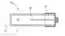
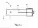
An embodiment will be explained hereunder with reference to the drawing. The Figure shows a longitudinal section through the test leak device.
The test leak device 10 consists of a cylindrical container 12 of glass with a closed bottom 14 at one end face and an open end at the opposite end face. The open end is tightly closed with an end cap 16 of metal. A capillary 18 is guided through the metal cap 16 along the longitudinal central axis of the cylinder 12.
The container 12 is filled with atmospheric air 20 having a proportion of helium of 5 ppm and a proportion of argon of 1%. The capillary 18 has a leakage rate of 10−6 mbar·l/s. The humidity of the air is about 40%. For the test leak device 10, this results in an effective gas flow of:
1·10−6 mbar·l/s·5 ppm=5·10−12 mbar·l/s for helium and 1·10−6 mbar·l/s·1%=1·10−8 mbar·l/s for argon.
Claims
1. A test leak device comprising a gas-filled container and a capillary penetrating a container wall,
wherein
a proportion of atmospheric air in the gas is at least 10%.
2. The test leak device of claim 1, wherein the capillary has a leakage rate of at most 10−6 mbar·l/s.
3. The test leak device of claim 1, wherein the atmospheric air has a relative humidity of less than 50%.
4. The test leak device of claim 1, wherein a proportion of helium in the atmospheric air is in a range from 3 to 7 ppm.
5. The test leak device of claim 1, wherein a proportion of argon in the atmospheric air is about 0.5% to 2%.
6. The test leak device of claim 1, wherein the container is cylindrical with a removable end cap through which the capillary is guided.
7. The test leak device of claim 6, wherein the cylinder is made of glass.
8. The test leak device of claim 6, wherein the removable end cap is made of a metal.
9. The test leak device of claim 6, wherein the container has a length of 5 cm at most and a diameter of 1 cm at most.
10. The test leak device of claim 3, wherein the atmospheric air has a relative humidity of less than 40%.
11. The test leak device of claim 4, wherein the proportion of helium in the atmospheric air is in a range from 4.5 to 5.5 ppm.
12. The test leak device of claim 5, wherein the proportion of argon in the atmospheric air is about 0.8% to 1.2%.
13. The test leak device of claim 9, wherein the container has a length of about 4 cm and a diameter of about 0.8 cm.
Images & Drawings included:
Sources:
- United States Patent and Trademark Office - verify current appl. status at the USPTO↗
Recent applications in this class:
- » 20250244191 2025-07-31
TEST LEAK DEVICE - » 20250164336 2025-05-22
LEAK DETECTION DEVICE AND LEAK DETECTION METHOD FOR SNIFFER LEAK DETECTION - » 20240402030 2024-12-05
FUNCTION VERIFICATION METHOD OF LIQUID LEAKAGE DETECTION MODULE - » 20240142330 2024-05-02
Systems and Methods for Detecting and Preventing Damage to Pipes - » 20230251159 2023-08-10
TEST LEAKAGE DEVICE - » 20230020261 2023-01-19
TEST GAS APPLICATOR - » 20220307934 2022-09-29
Calibration device and self-testing device of a normally closed smart water supply control system with leak detection - » 20210231516 2021-07-29
Leak Detection System and Method - » 20210223135 2021-07-22
Test device and calibrating method - » 20210223134 2021-07-22
TEST DEVICE AND CALIBRATING METHOD
Recent applications for this Assignee:
- » 20230021741 2023-01-26
Method for adapting the concentration of a sample gas in a gas mixture to be analysed by a gas chromatograph assembly, and chromatograph assembly therefore - » 20220181709 2022-06-09
Tightness test of a liquid filled test object - » 20220136997 2022-05-05
Gas detector with an ionizing device - » 20210318271 2021-10-14
Method for adapting the concentration of a sample gas in a gas mixture to be analysed by a gas chromatograph assembly, and chromatograph assembly therefore - » 20210239562 2021-08-05
Method for determining the relative position of a gas leak - » 20210231561 2021-07-29
Connecting device for connecting a gas sensor - » 20210231517 2021-07-29
Sniffing leak detector with switching valve and buffer chamber - » 20210048367 2021-02-18
Method for leak testing using a film chamber with ventilated measuring volume - » 20200378862 2020-12-03
Method for leak testing with a foil chamber with vented measurement volume - » 20200271540 2020-08-27
Device and method for distinguishing a test gas escaping from a leak from interfering gas