Variable Second Pad Keel
US20160207591A1
2016-07-21
14/846,268
2015-09-04
Abstract:
By including a Variable Second Pad Keel, a watercraft experiences a reduction in Slamming forces as well as generally improved Seakeeping and Seakindliness.
Inventors:
- Steven C.H. Loui 3 🇺🇸 Honolulu, HI, United States
- Gary Johnson 2 🇺🇸 Honolulu, HI, United States
- Michael Buelsing 2 🇺🇸 Honolulu, HI, United States
- William Lawson 2 🇺🇸 Honolulu, HI, United States
- Scott Yamashita 12 🇺🇸 Honolulu, HI, United States
- Charles Field 1 🇺🇸 Honolulu, HI, United States
Assignee:
- NAVATEK, LTD., A HAWAII CORPORATION 2 🇺🇸 HONOLULU, HI, United States
Interested in similar patents?
Get notified when new applications in this technology area are published.
Classification:
B63B1/042 » CPC further
Hydrodynamic or hydrostatic features of hulls or of hydrofoils deriving lift mainly from water displacement with single hull the underpart of which being partly provided with channels or the like, e.g. catamaran shaped
B63B1/18 » CPC main
Hydrodynamic or hydrostatic features of hulls or of hydrofoils deriving additional lift from hydrodynamic forces of hydroplane type
B63B1/04 » CPC further
Hydrodynamic or hydrostatic features of hulls or of hydrofoils deriving lift mainly from water displacement with single hull
Description
RELATED APPLICATIONS
This continuation-in-part application claims the benefit of U.S. Non-Provisional application Ser. No. 14/599,164 filed Jan. 16, 2015, the disclosures of which are herein incorporated by reference.
TECHNICAL FIELD
The field discussed herein relates generally to watercraft hull configuration.
BACKGROUND
It is well known that flat, zero-Deadrise hull surfaces have the highest planing efficiencies, and many prior art watercraft incorporate flat sections to hull bottoms to improve total hull planing efficiency. Planing efficiency refers to efficiency of energy use while underway; a hull having high planing efficiency can use less fuel and produce less wake than a hull having low planing efficiency. However, it is also well known that wide, flat planing surfaces generate strong impacts to the hull (and watercraft occupants) when such a planing surface re-contacts the water surface after separating from the water surface, for instance when planing through choppy conditions and when re-contacting the water surface after the watercraft launches off wave crests. These strong impacts are called “watercraft slamming”. To minimize slamming associated with flat planing hulls, prior art watercraft have limited the flat hull areas to selective portions of the hull. Typically, the flat hull areas employed by prior art watercraft have been relatively short, narrow, wedge or delta-shaped areas of the hull keel that are widest at the transom, taper in width forward from the transom, and blend into V-shaped sections in the hull's forebody.
Some prior art watercraft designs employ truncated, or “padded”, V-shaped hull structures wherein the bottom of a V-shaped hull has been cut away (“truncated”) to create a flat “pad” area integral to the hull's bottom. Other prior art watercraft have employed distinctly “flat pad keels” wherein the flat pad projects below the theoretical convergence of the sides of a watercraft's V-shaped hull. It is well known that truncated V-shaped hulls and pad keels can cause maneuvering and turning problems such as side slip and lack of directionality. As a result, prior art watercraft with flat hull portions frequently added strakes, reverse strakes, sponsons or other structures to the hull to increase hull grip.
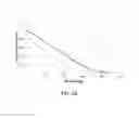
FIG. 0A shows a relationship between lift fraction of flat plate and Deadrise, but does not explain the relationship of slamming force to those variables. As shown by FIG. 0A, the 0 Deadrise of a pad keel provides significantly more lift, about 33% more than a 20 degree Deadrise V-shaped hull, if the Pad Keel Sides have Deadrise of 45 degrees or greater, the peak slamming pressure as the hull is immersed will be no greater than the initial entry pressure. There is unmet demand for a hull design with >45 Deadrise Pad Keel Sides with improved Seakindliness, Seakeeping, substantially reduced Slamming, with less viscous drag and minimal reduction in Planing Efficiency and with Acceptable Slamming Force. Therefore, the technical problem to be solved is to design a Hull that combines a large Pad Keel with Pad Keel Sides whose Deadrise of 45 degrees or greater create a Hull with improved Seakindliness, Seakeeping, substantially reduced Slamming, with minimal reduction in Planing Efficiency, compared to prior art deep V-hulls and Planing Hulls.
The foregoing examples of the related art and limitations related therewith are intended to be illustrative and not exclusive. Other limitations of the related art will become apparent upon a reading of the specification and a study of the drawings.
SUMMARY
The following examples and aspects thereof are described and illustrated in conjunction with systems, tools, and methods that are meant to be exemplary and illustrative, not limiting in scope. In various examples, one or more of the above-described problems have been reduced or eliminated, while other examples are directed to other improvements.
As discussed herein, watercraft can benefit from Hull designs utilizing a Second Pad Keel of varying width, surface shape, and Taper. Such Hull designs can include a Self-Flooding and Self-Bailing Pad Keel Plenum equipped with a Bow Pocket Vent.
As shown by FIG. 0A, the 0 Deadrise of a pad keel provides significantly more lift, about 33% more than a 20 degree Deadrise V-shaped hull. Therefore, this allows the Pad Keel Sides to be designed to mitigate slamming rather than generating lift. FIG. 0B shows the effects of Deadrise and the relationship between pressure forces of wedge sections (e.g. a V-shaped hull) from initial entry through increasing immersion. As shown in FIG. 0B, if the Pad Keel Sides have Deadrise of 45 degrees or greater, the peak slamming pressure as the hull is immersed will be no greater than the initial entry pressure, which translates to a compression force if the hydrodynamics of the hull are analogized to an automotive shock absorber.
Advantageously, Hull designs benefiting, from these advancements outperform those having merely flat surfaces, V-shaped, previous Pad Keel, hulls. Hull designs including advancements disclosed herein enjoy high Planing, efficiency without high Slamming, and exhibit excellent Seakindliness and Seakeeping. By analogy, the hydrodynamic properties of a Second Pad Keel allow it to function on a watercraft like an automotive strut or shock absorber functions on a car. This improves the experience of operating the watercraft in the way that an automotive shock absorber improves the experience of driving a car.
Herein as described are Hull configurations employing a Second Pad Keel of varying width, surface shape. Taper, and Deadrise (depending on the purpose of the craft). Embodiments of the Hull can include a Pad Keel Plenum that Self-Floods and Self-Bails via a Bow Pocket Vent on the Pad Keel Sides. Advantageously, this provides a novel watercraft made with the Hull that has improved Seakeeping, Seakindliness, payload, and Planing efficiency, and reduced Slamming compared with prior art Planing hulls and V-Hulls. This is achieved by combining the efficiency benefits of a wider and/or multiple Pad Keels without having negative Seakeeping or handling problems associated with a Deep-V The Hull. The Hull of the invention can be retrofitted to existing watercraft and can be employed in new watercraft designs.
The Self-Flooding and Self-Bailing Pad Keel embodiments of the invention dynamically improve Seakeeping and Seakindliness over a range of speeds. A Bow Pocket Vent provides atmospheric air ingress to the interior of a Hollow Plenum and allows the Plenum to Self-Flood and Self-Bail.
BRIEF DESCRIPTION OF THE DRAWINGS
FIG. 0A is a graph of the relationship between lift fraction of flat plate versus its Deadrise. FIG. 0B is a graph of the relationship between pressure and Deadrise of a wedge upon water entry
FIGS. 1A-1H and 1J depict a typical deep-V watercraft with a Concentric Pad Keel that can be attached (in FIG. 1A) or is attached (in FIGS. 1B-1J) to the bottom of the Hull of the typical deep-V watercraft. There is no FIG. 11 (1-“eye”).
FIGS. 2A-2C generally depict the water flow present during the impact of a Second Pad Keel and the water as well as the forces present during an impact of a V-Hull and the water.
FIGS. 3A-H and 3J depict a Uniform Second Pad Keel. There is no FIG. 3I (3-“eye”).
FIGS. 4A-C depict a Truncated, Ventilating Second Pad Keel.
FIGS. 5A-C depict a Truncated, Aft Rocketed Second Pad Keel.
FIGS. 6A-C depict an Aft Expanding Second Pad Keel.
FIGS. 7A-C depict an Aft Expanding and Rockered Second Pad Keel.
FIGS. 8A-C depict an Aft Rockered Second Pad Keel.
FIGS. 9A-C depict an Aft Expanding, Truncated and Ventilating Second Pad Keel.
FIGS. 10A-C depict an Aft Expanding, Truncated and Aft Rocketed Second Pad Keel.
FIGS. 11A-C depict an Aft Expanding, Truncated and Rockered Second Pad Keel.
DETAILED DESCRIPTION
In the following description, details are presented to provide a thorough understanding of the invention. One skilled in the relevant art will recognize, however, that the concepts and techniques disclosed herein can be practiced without one or more of the specific details, or in combination with other components, etc. In other instances, well-known implementations or operations are not shown or described in detail to avoid obscuring aspects of various examples disclosed herein.
“−6 to +6 Deadrise” means Deadrise of −6 Degrees to +6 Degrees and is otherwise known as “Flat” (in the case of +/−1 Degree Deadrise). “Flat Deadrise” have −6 to +6 Average Deadrise.
“6-19 Deadrise” means Deadrise greater than 6 degrees but less than 20 degrees and is known as “Low Deadrise”.
“20-45 Deadrise” means Deadrise greater than or equal to 20 degrees but less than 45 Degrees and is otherwise known as “High Deadrise”.
“>45” Deadrise means Deadrise of 45 to 90 Degrees and is otherwise known as “Ultra High Deadrise”.
“Above” means higher in elevation when viewed from the Bow or Transom.
“Acceptable Slamming Force” is a qualitative measure of the degree of Slamming that persons on a watercraft will experience, without feeling, extreme discomfort. Acceptable Slamming Force is a personal variable and is very dependent upon the rate of deceleration during a Slam.
“Aft End” means, with respect to a Second Pad Keel, an end of the Second Pad Keel, at a point along the Centerline of the watercraft, at of the Forward End of the Second Pad Keel.
“Angle of Attack” means the angle that the line between fore and of points on a Hull, or a longitudinal part of a Hull, make with the incoming flow.
“Beam” is the width of a watercraft.
“Below” means lower in elevation when viewed from the Bow or Transom.
“Blend” means, with respect to portions of a hull, to join two or more panels continuously so as to provide a smooth surface at their intersection(s).
“Bow” means the forward part of a watercraft.
“Bow Pocket Vent” means an opening at the Bow on a Pad Keel Side with a Spray Deflector that provides a channel between the surface of the Pad Keel and the internal cavity of a Hollow Plenum Pad Keel.
“Chine” means the edge formed on the Hull of a flat bottomed or V-bottomed watercraft where the Hull bottom joins the Hull sides,
“Concentric Pad Keel” means a Hull structure comprised of concentric and symmetric Flat Pad Keels with the larger or Main Pad Keel Above the smaller or Second Pad Keel. The Main Pad Keel is connected and depends below the rest of a watercraft Hull on Ultra High Deadrise Main Pad Keel Sides. The Second Pad Keel is connected and depends below the Main Pad Keel on Ultra High Deadrise Second Pad Keel Sides. There may be additional Pad Keels Above the Main Pad Keel Sides.
“Deadrise,” means (in a Transom or Bow view of the Hull) the angle of a section of a Hull relative to the water when the watercraft is not heeled over, i.e. when the watercraft is upright, e.g., “Low Deadrise,” “High Deadrise,” and “Ultra High” Deadrise.
“Deep-V Hull” means a Hull with High Deadrise at the Transom when measured from the centerline of the Transom to the outboard edge of the Chine.
“Design Waterline Beam” means the width of a watercraft as measured in the Y dimension at the watercraft's waterline when the watercraft is loaded to its design condition.
“Design Waterline Length” means the length of a watercraft as measured in the X dimension at the watercraft's waterline when the watercraft is loaded to its design condition.
“Disturbed Water Surface” means the waves or ripples caused on the water surface from a Hull entering the water.
“Expand,” “Expands,” or “Expanding” means, with reference to the Second Pad Keel, that the Width of the Second Pad Keel Sides at the connection with the Main Pad Keel increases Fore to Aft and blends to the width of the Main Pad Keel at the Transom or within half the distance between the Longitudinal Center of Buoyancy and the Transom.
“Fine Entry,” or “Fine Entry Bow” means the shape of the Bow that is designed to slice or cleave through waves. A typical Fine Entry Bow has a Forefoot Deadrise greater than 45 degrees.
“Forebody” means the part of the watercraft forward of the Midship.
“Forefoot” means the part of the Keel which curves and rises to meet the Stem.
“Forward End” means, with respect to a Second Pad Keel, a region of the Second Pad Keel, forward of Midship along the Centerline of the watercraft.
“Forward Apex” means, with respect to a Second Pad Keel, a forward most point of the Second Pad Keel.
“grips” as used generically with a lowercase “g” means latitudinal pressure exerted against water by longitudinal features of a watercraft hull. Grip is useful in controlling the direction of the watercraft, particularly at high speeds. Am example of usage: “Although traveling at speeds in excess of 50 knots, the watercraft's Hull had good grip and did not spin out during turns.”
“Height” means a measurement of a watercraft, a watercraft structural element, or a watercraft feature in the Z Dimension.
“Hollow Plenum” means the internal cavity formed by the Pad Keel, Pad Keel Sides and an air and watertight top cover joining to both Pad Keel Sides and the adjacent Hull Panel(s) Above it. It functions to conduct air or water to openings in the Pad Keel or Pad Keel Sides to Self-Bail or Self-Flood the cavity. A Bow Pocket Vent provides an access for atmospheric air entry when the Plenum is Self-Bailing or to allow air to vent out of the Plenum when the Plenum is Self-Flooding.
“hull” (in lower case letters) means the body of a prior art watercraft between the deck (which may be the inner surface of the hull) and the keel. The hull is the shaped structure of the bottom of a watercraft that provides buoyancy and seaworthiness. “Hull”, with an initial capital H, means the Hull of an embodiment of the invention described and claimed herein.
“Hull Chine Beam” means the width of as watercraft as measured between its port and starboard Chines.
“Hull Modification” means any change or alternation made to a Hull that differs from its original design.
“Heel,” “Heeled,” or “Heeling” refer to a watercraft that is leaning either to starboard or to port.
“Immersed Area” or “Wetted Surface Area” means the wetted portion of a Hull and appendages at and below the waterline.
“Initial Slam” means the initial impact of a Hull on a water surface during Re-entry e.g. by impacting a wave or the ocean surface while a watercraft is underway.
“Inwardly-Stepped” means a series of transverse (Y Dimension) discontinuities in the direction of the centerline in a panel or panels of a watercraft's hull.
“Keel,” means the structure of a watercraft hull that extends longitudinally along the center of its bottom and that often projects from the bottom. See also, “Pad Keel” and “Pad Keel Sides”.
“Length” is synonymous with Design Waterline Length and is a measurement in the X Dimension.
“Length To Beam Ratio” is the ratio of Design Waterline Length to Design Waterline Beam For example, a Hull with a Design Waterline Length of 30 and a Design Waterline Bean of 5 will have a Length To Beam Ratio of 6.
“Longitudinal Center of Buoyancy” means the point on the Keel, along the Centerline, in the X dimension, at which the watercraft balances with respect to Buoyancy.
“Longitudinal Step” means a fore and aft vertical discontinuity on the Hull bottom surface and appears as a step when viewed in Transom or Bow views.
“Main Pad Keel” or “MPK” means the Pad Keel in a Variable Second Pad Keel configuration Above the Second Pad Keel.
“Main Pad Keel Sides” means the Ultra High Deadrise Hull Panels that connect the Main Pad Keel and depend from the remainder of the Hull Above it.
“Midship” means the location on a watercraft that is approximately equally distant from Bow and stern, e.g. a location between 40% and 60% of the length from Bow to stem.
“Outboard” means in a position that is away from the center line of the hull of a watercraft.
“Pad Keel” means the flat Hull surface that protects below the theoretical convergence of the sides of the watercraft's V-shaped Hull, Pad Keels increase hydrodynamic lift compared to traditional keels when a watercraft is underway.
“Pad Keel Sides” means the Ultra High Deadrise Hull Panels that connect a Pad Keel to, and depend from, the remainder of the Hull Above it.
“Pad Keel Side Ventilator” means a Pad Keel Side Hull Panel that is Inwardly-Stepped towards the centerline from the Pad Keel Sides, tapers at its aft end to blend with the Pad Keel Sides, and has one or more openings at its forward end, through which air and water can Self-Bail and Self-Flood the Hollow Plenum and provide air ventilation to the Panels aft of it when the craft is underway.
“Panel” means a plating component of a Hull. A combination of Panels and other components of a Hull form the Hull itself.
“Planing” means riding on the surface of water as in “hydroplaning” or “aquaplaning,” where lift is provided by hydrodynamic pressure.
“Planing Hull” means a Hull shape that allows at least part of its Keel to rise above the water's free surface, and to ride up on the after part of the Hull, allowing the watercraft to move much faster with some of the watercraft on the surface of the water.
“Planing Surface” or “Planing Surfaces” mean a section, or sections, of a Hull having Flat Deadrise that operate to ride at least partially on the surface of water when a watercraft is underway.
“Plenum” is a synonym of “Hollow Plenum”.
“Re-entry” means the reentry of a watercraft hull into a water surface after all or part of the hull has left the water's surface, typically when the watercraft is underway, e.g., through choppy water or has been launched off a wave crest.
“Rocker” or “Rockered” means, with reference to the Second Pad Keel, that the Height of the Second Pad Keel Tapers in the Z dimension at its Aft End to a point forward of the Transom.
“Rough”, “Rough Water”, or “Rough Seas” are synonyms that mean wind and wave conditions that cause uncomfortable watercraft motions.
“Seakeeping” or “Seakeeping ability” are synonyms for the qualitative measure of a watercraft's ability to maintain functionality in Rough Water.
“Seakindly” or “Seakindliness” are synonyms for the qualitative measure of a watercraft's ability to maintain occupant comfort in Rough Water.
“Second Pad Keel” or “SPK” means the Pad Keel Below the Main Pad Keel on a Hull narrower than the Main Pad Keel.
“Second Pad Keel Sides” means the Ultra High Deadrise Hull Panels that connect the Second Pad Keel to, and depend from, the Main Pad Keel.
“Self-Bailing” or “Self-Bail” means a feature of a watercraft that drains water by air pressure or gravity, e.g. through an opening or by pressure gradient.
“Self-Flooding” or “Self-Flood” means a feature of a watercraft that allows water to enter and flood an internal Plenum automatically, e.g. by water pressure alone.
“Slam” or “Slamming” means to crash down hard on a water surface, referring to the action of a watercraft.
“Spray Deflector” means a covering on a Bow Pocket Vent that prevents incoming spray from entering the opening.
“Stem” means the forward most part of the Bow.
“Taper” means a change in Width, or Height over the Length.
“Transom” means the flat surface forming the stern of a watercraft.
“Transverse” means in the direction of port to starboard or vice versa.
“Transverse Step” means a port to starboard (athwartship) vertical discontinuity to a watercraft's Hull and it appears as a step in the Hull bottom in a side view.
“Transversely Stepped” means a Hull including a single or multiple Transverse Steps.
“Truncated” means, with reference to a Second Pad Keel, in the X Dimension, that the Second Pad Keel terminates at a location forward of the Transom, aft of which, a Main Pad Keel continues.
“Ultra High Deadrise” or “UHD” refers to a Hull, or portion of a Hull, that is sharply V-shaped and has Deadrise of between 45 and 90 degrees.
“Undisturbed Water Surface” means the surface of water yet to be entered by the Hull.
“Uniform” means, with reference to the Second Pad Keel, that the Second Pad Keel runs the length of the Main Pad Keel from Transom to Forward Apex, is neither Expanding nor Rockered, and Tapers Vertically at the Forward End to ½′ or less at the Forward Apex.
“Un-Wet” means in reduced contact with water through aeration.
“Variable Second Pad Keel” means a Hull structure comprised of symmetric Flat Pad Keels with the larger or Main Pad Keel Above the smaller or Second Pad Keel. The Second Pad Keel is connected to, and depends Below, the Main Pad Keel on Ultra High Deadrise Second Pad Keel Sides. A Variable Second Pad Keel differs from a Concentric Pad Keel in that it has a Taper through either an Expanding and/or Rockered Second Pad Keel.
“Ventilate” or “Ventilating” means to conduct atmospheric air outboard through submerged Hull openings to partially un-wet submerged Hull surfaces using a negative pressure gradient caused by the Venturi effect while the craft is underway. The un-wetting of submerged Hull surfaces reduces the Hull's Viscous Drag.
“Ventilating Air” means atmospheric air used to Ventilate the Hull.
“V-Hull” means a Hull composed of two distinct planar surfaces that intersect at the Keel at a Deadrise. A V-Hull is so-named because it resembles the shape of the letter “V” in Bow view.
“Viscous Drag” is friction force acting, opposite to the relative motion of a watercraft moving through a fluid.
“Water Entry Deceleration” means, with reference to a Hull entering water, or a portion of a Hull entering water, the deceleration of a Hull as the Hull enters the water.
“Watercraft Re-Entry Initial Deceleration” means, with reference to a Hull Re-entering water, or a portion of a Hull Re-entering water, the deceleration of a Hull as the Second Pad Keel Re-enters the water.
“Watercraft Re-Entry Vertical Deceleration” means with reference to a Hull Re-entering water, or a portion of a Hull Re-entering water, the decrease in vertical velocity of the Hull as the Hull Re-enters the water.
“Waterline” means the level normally reached by the water on the side of a watercraft.
“Wedge Ventilator” means a wedge shaped Hull Panel that projects downward at its aft end from a Longitudinal Step, tapers at its forward end to blend with the Longitudinal Step, and has one or more openings at its aft end, through which air and water can Self-Bail and Self-Flood the Hollow Plenum and provide air ventilation to the Panels aft of it when the craft is underway.
“Width” defines a measurement in the Y Dimension.
“X Dimension” defines a measurement along the line from bow to stern, otherwise known as Length.
“Y Dimension” defines a measurement along the line from port to starboard, otherwise known as Width.
“Z Dimension” defines a measurement along the line from deck to keel, otherwise known as Height.
A watercraft's Planing performance efficiency is improved and a reduction in Slamming Forces is realized by having a Variable Second Pad Keel structure configuration. A watercraft designed with a Variable Second Pad Keel in accordance with the teachings provided herein has a Flat Main Pad Keel projecting, downward on Main Pad Keel Sides from a typically V-shaped watercraft Hull. The Main Pad Keel has Main Pad Keel Sides with Deadrise between 45 degrees to 90 degrees. The height of the Main Pad Keel sides at the Transom is 20% to 30% of the Main Pad Keel width at the Transom. The Main Pad Keel is wiriest at the Transom and its width Tapers towards the Bow. A Second Pad Keel, smaller than the Main Pad Keel, projects downwards from the Main Pad Keel on Second Pad Keel Sides with Deadrise between 45 and 90 degrees. The Second Pad Keel is narrower and on the same longitudinal centerline as the Main Pad Keel and extends the full or optionally only a partial length of the Main Pad Keel. The average Width measured at the Transom of the Main Pad Keel and Second Pad Keel for a watercraft with a Length to Beam Ratio of less than three (3) is 10% to 20% of the Hall's Chine Beam measured at its Transom. The average Width measured at the Transom of the Main Pad Keel and Second Pad Keel for a watercraft with a Length to Beam Ratio of between three (3) and four (4) is 15% to 25% of the Hull's Chine Beam measured at its Transom. The average Width measured at the Transom of the Main Pad Keel and Second Pad Keel for a watercraft with a Length To Beam Ratio of four (4) or greater is 20% to 30% of the Hull's Chine Beam measured at its Transom. In alternative embodiments, the width, height or length of the Main Pad Keel or Second Pad Keel can be modified through mechanical actuation.
Shown in FIG. 1A is a Transom view 100 of a typical Deep-V watercraft with an exploded view of a Main Pad Keel and Second Pad Keel Assembly 102 that is detached from the Hull 104 in FIG. 1A and is shown attached to the bottom of the Hull 106 in FIGS. 1B to 1H and 1J. FIG. 1B is a bottom view 108 of this watercraft and FIG. 1C is a side view 110 of this watercraft. FIGS. 1D through 1H are section views of this watercraft from the Forefoot 112 to the Transom 114 whereby the Main Pad Keel 116 projects downward from the bottom of the Hull 104 on Main Pad Keel Sides 118 of 49 degrees. A Second Pad Keel 120 projects downward from the Main Pad Keel 116 from Second Pad Keel Sides 122 of 90 degrees. FIG. 1J shows an isometric (aka perspective) view 124 of this watercraft. The Main Pad Keel 126 and Second Pad Keel 128 extend longitudinally from their apex at the Bow 130 all the way to the Transom 132. The Main Pad Keel 126 and Second Pad Keel 128 are widest at the Transom 132 and Taper in width towards the Bow 130. The watercraft in FIGS. 1A to 1H and 1J has a Design Waterline Length of 18.4′ and a Design Waterline Beam of 7′. Its Length to Beam Ratio is 2.62 and the average width of the Main Pad Keel 126 and Second Pad Keel 128 at the Transom 132 is approximately 15% of its Hull Chine Beam 134 at the Transom 132.
When the Hull 106 of the watercraft shown in FIGS. 1A to 1H and 1J reenters the water after becoming partially or fully airborne from the water's surface, the Second Pad Keel 128 is the first Hull structure to make contact. The dimensions of the Second Pad Keel 128 are selected such that its impact generates an Acceptable Slamming Force when falling. The Second Pad Keel 128 impact imparts downward momentum to the water with a force perpendicular to its surface.
FIG. 2A shows the flow directions 202 of the displaced water 204 resulting from a Pad Keel 206 entering the water surface with vertical velocity “v” 208. In a watercraft equipped with a Second Pad Keel, shown in FIG. 2C, the watercraft experiences Watercraft Re-Entry Initial Deceleration from the large vertical momentum imparted by the Second Pad Keel 206 to the water 210 under it. Compare this to the water displacement 212 in FIG. 2B as the result of a V-shaped structure 214 entering the water surface 216 with vertical velocity 218. The impact forces act normal to its immersed bull panels 220 resulting in lower vertical momentum imparted to the water 222 as a result of the Deadrise 224 of a watercraft equipped with hull panels having Deadrise 224 in FIG. 28 and therefore lower Watercraft Re-Entry Vertical Deceleration compared to the Pad Keel 206 in FIG. 2A.
As shown in FIG. 2C, upon Re-entry of a watercraft equipped with a Main Pad Keel and a Second Pad Keel, the Main Pad Keel 226 impacts the water surface 228 shortly after the Second Pad Keel 230 and at a lower velocity than the Second Pad Keel 230 as a result of the Watercraft Reentry Initial Deceleration. The Main Pad Keel 226 impacts a Disturbed Water Surface 232 that has been displaced circumferentially by the impact of the Second Pad Keel 230. Also, the water 234 below the Main Pad Keel 226 and immediately adjacent to the Second Pad Keel Sides 236 is accelerating downwardly as shown by the flow direction 238 in FIG. 2C. The result of these factors is to reduce the force of a Slam of the Main Pad Keel 226 compared to if it had landed on an Undisturbed Water Surface without a Second Pad Keel 230 landing immediately before it. The Second Pad Keel arrangement 240 therefore allows a watercraft having a wider Main Pad Keel 226 to have a Slam force that is comparable to a narrower Pad Keel 206 without a Second Pad Keel arrangement 240.
In reference to FIG. 2C as a watercraft equipped with a Main Pad Keel and Second Pad Keel continues its downward Reentry, it experiences additional high Water Entry Deceleration from the large vertical momentum imparted to the water under the wider and larger immersed Area of the Main Pad Keel 226. Next, the Main Pad Keel Sides 242 become immersed. It is well known that Hull Panels with Ultra-high Deadrise when Re-entering the water surface 228 have relatively small changes in pressure measured normal to the immersed Hull Panel surfaces. As the immersion of the Main Pad Keel Sides 242 progresses, it does not contribute a significant amount to further Water Entry Deceleration; however, the large vertical momentum imparted to the water under the Main Pad Keel 226 and Second Pad Keel 230 continues.
When the Second Pad Keel 240 is fully immersed, the ongoing Water Entry Deceleration from the Second Pad Keel 240 has continued long enough that the watercraft vertical plunging velocity 244 has slowed. Therefore, when parts of the Hull above the Main Pad Keel Sides 242 impact the water surface, the Slamming forces are Acceptable Slamming Forces.
FIGS. 3A to 3H and 3J show another embodiment of the invention. The Second Pad Keel 302 of the Concentric Pad Keel 304 terminates at Midship 306, rather than extending longitudinally the full length of the watercraft to the Transom 308.
FIG. 3A shows the Bow Pocket Vents 310 located on the forward end of the port and starboard Main Pad Keel Sides 312, aft of the Bow Stem 314. This opening has a Spray Deflector 316 “pocket” to allow atmospheric air to vent the Hollow Plenum 318, shown in FIGS. 3F-3H. On the forward bottom of the Main Pad Keel 320 is an opening 322 to allow air to enter, or “vent”, the Second Pad Keel Plenum 324, shown in FIG. 3G, and shown in the exploded view with dashed lines in reference to Bow Pocket Vents 310. The aft end of the Second Pad Keel Plenum 324 is open, allowing air to ventilate the Hull surfaces aft of the outlet to reduce Wetted Surface Area and Viscous Drag at Planing speeds.
At zero and low speeds the Concentric Pad Keel Plenums 318, 324 Self-Flood with water entering through the Plenum openings 322 below the water surface and displace air in the Plenum which exits through the Bow Pocket Vent 310. Water in the Plenums lowers the vertical center of gravity of the watercraft to reduce motions at zero and low speeds, to improve Seakeeping, and to improve Seakindliness. When the watercraft accelerates to Planing speeds, the BOW Pocket Vent 310 rises above the water surface, and the intake air feeds into the Plenums 318, 324 of the Concentric Pad Keel, which Self-Bail through outlets 322 on the Concentric Pad Keel.
Cross-sections 326 of the Concentric Pad Keel 304, shown in FIGS. 3D through 3H, show the Main Pad Keel Plenum 318 and the Second Pad Keel Plenum 324 terminating near mid-length 306 (shown in FIG. 3B) of the Main Pad Keel 320 and at the aft end of the Second Pad Keel 302 (shown in FIG. 3C).
FIG. 3J shows an exploded bottom isometric view 328 of the Concentric Pad Keel 304, and shows the Self-Flood and Self-Bail channel openings 330 between the Main Pad Keel Plenum 318 and the Second Pad Keel Plenum 324. Structurally, the Second Pad Keel 302 can be fastened to the Main Pad Keel 320 as an add-on and can be fabricated from the same material as the hull or a different material based on its intended use. For example, for grounding protection, the Second Pad Keel 302 can be fabricated from a sacrificial material such as foam, plastic, aluminum or another known or convenient material.
FIGS. 4A-C depict a Uniform Second Pad Keel, which is another embodiment. As depicted in FIGS. 4A-C, the Second Pad Keel 402 terminates at the Transom 404, extending longitudinally the full length of the watercraft from the Forward Apex 406 to the Transom 404. As shown in FIGS. 4A-C, the Second Pad Keel 402 is neither Expanding in the Y Dimension nor Rockered in the Z Dimension. In this example, the Second Pad Keel 402 Tapers in the Z Dimension in the Forward End from 1″ at the Transom 404 to ½″ at the Forward Apex 406. Other rates of Taper from the Forward End can be used.
FIGS. 5A-C depict a Truncated, Ventilating Second Pad Keel. As depicted in FIGS. 5A-C, the Second Pad Keel 502 Truncates at a point Forward of the Transom 504. The purpose for this is to Ventilate the Main Pad Keel 506 through openings in the Plenum 508. This configuration is neither Expanding in the Y dimension nor Rockered in the Z dimension.
FIGS. 6A-C depict a Truncated, Aft Rockered Second Pad Keel. As depicted in FIGS. 6A-C, the Second Pad Keel 602 Rockers to a point forward of the Transom 604. The Height of the Second Pad Keel Sides 606 Tapers from about 1″ at the Keel to 0″-½″ at its Aft End. This configuration is not Expanding.
FIGS. 7A-C depict an Aft Expanding Second Pad Keel. This is an embodiment where the Second Pad Keel 702 Tapers Outboard so that the Second Pad Keel Sides 704 blend with the Main Pad Keel Sides 706. The Deadrise on the Second Pad Keel Sides 704 varies from 90° at the Forward End of the Taper to a Deadrise equal to the Main Pad Keel Sides 706 at the Aft End of the Taper. As depicted, this Taper in Width constitutes variability in the Y dimension.
FIGS. 8A-C depict an Aft Expanding and Rockered Second Pad Keel. As depicted in FIGS. 8A-C, the Second Pad Keel 802 Tapers Outboard so that the Second Pad Keel Sides 804 blend with the Main Pad Keel Sides 806. The Deadrise on the Second Pad Keel Sides 804 varies from 90° at the Forward End of the Taper to a Deadrise matching the Main Pad Keel Sides 806 at the Aft End of the Taper. Additionally, the Second Pad Keel 802 Rockers towards its Aft End 808. The height of the Second Pad Keel Sides 804 Tapers from about 1″ at the keel to 0″-½″ at its Aft End 808.
FIGS. 9A-C depict an Aft End Rocketed Second Pad Keel. As depicted in FIGS. 9A-C, the Second Pad Keel 902 Rockers to the Transom 904. The Height of the Second Pad Keel Sides 906 Tapers front about 1″ at the Keel to 0″-½″ at the Transom 904. As depicted, this Taper in Height constitutes variability in the Z dimension.
FIGS. 10A-C depict an Aft Expanding, Truncated and Ventilating Second Pad Keel. As depicted in FIG. 10A-C, the Second Pad Keel 1002 Tapers Outboard so that the Second Pad Keel Sides 1004, which have constant Deadrise of 90° at the Forward Apex 1006, blend with the Main Pad Keel Sides 1008 at a point forward of the Transom 1010.
FIGS. 11A-C depict an Aft Expanding, Truncated and Rockered Second Pad Keel. As depicted in FIGS. 11A-C, the Second Pad Keel 1102 Tapers Outboard so that the Second Pad Keel Sides 1104, having constant Deadrise of 90° at the Forward Apex 1106, blend with the Main Pad Keel Sides 1108 at a point forward of the Transom 1110. Additionally, the Second Pad Keel 1102 Rockers to a point forward of the Transom 1110, where it is Truncated. The Height of the Second Pad Keel Sides 1104 Tapers from about 1″ at the Keel to 0″-½″ at the Aft End of the watercraft.
It will be appreciated to those skilled in the art that the preceding examples and embodiments are exemplary and not limiting to the scope of the present invention. It is intended that all permutations, enhancements, equivalents, and improvements thereto that are apparent to those skilled in the art upon a reading of the specification and a study of the drawings are included within the true spirit and scope of the present invention. It is therefore intended that the following appended claims include all such modifications, permutations and equivalents as fall within the true spirit and scope of the present invention.
Claims
What is claimed:1. A watercraft including a Deep-V Planing Hull comprising:
a Fine Entry Bow:
a Transom; and
a Variable Second Pad Keel having,
a Main Pad Keel projecting downward from the Deep-V Planing Hull on Ultra High Deadrise Main Pad Keel Sides, and
a Second Pad Keel projecting downward from the Main Pad Keel on Ultra High Deadrise Second Pad Keel Sides; wherein the Second Pad Keel Sides Taper from the Transom to an apex at the Forefoot of the Fine Entry Bow.
2. The watercraft of claim 1, wherein the Second Pad Keel is Uniform.
3. The watercraft of claim 1, wherein the Second Pad Keel is Truncated forward of the Transom; and wherein the Plenum in the Second Pad Keel is ventilated, thereby ventilating the Main Pad Keel.
4. The watercraft of claim 1, wherein the Second Pad Keel is Rocketed.
5. The watercraft of claim 4, wherein the Second Pad Keel is Rocketed from a Height of 1 inch at the Forward End to a Height in a range of 0 inches to ½ inches as die Aft End.
6. The watercraft of claim 1, wherein the Second Pad Keel Expands in Width to Blend with the Main Pad Keel Sides; wherein the Second Pad Keel Sides Deadrise varies from 90 degrees at a Forward End of the Second Pad Keel to Blend to the Deadrise of the Main Pad Keel Sides at the Aft End of the Second Pad Keel.
7. The watercraft of claim 1, wherein the Second Pad Keel Expands in Width to Blend with the Main Pad keel Sides; wherein the Second Pad keel Sides Deadrise varies from 90 degrees at a Forward End of the Second Pad Keel to Blend to the Deadrise of the Main Pad Keel Sides at the Aft End of the Second Pad Keel; and wherein the Second Pad Keel is Rockered.
8. The watercraft of claim 7, wherein the Second Pad Keel is Rockered from a height of 1 inch to a height in a range of 0 inches to ½ inches.
9. The watercraft of claim 1, wherein the Second Pad Keel is Rockered to the Transom.
10. The watercraft of claim 6, wherein the Second Pad Keel is Rockered from a height of 1 inch to a height in a range of 0 inches to ½ inches.
11. The watercraft of claim 1, wherein the Second Pad Keel Expands with the Second Pad Keel Sides having a constant deadrise of 90 degrees; and wherein the Second Pad Keel Sides Blend with the Main Pad Keel Sides at a point forward of the Transom.
12. The watercraft of claim 1, wherein the Second Pad Keel Expands with Second Pad Keel Sides having a constant Deadrise of 90 degrees; wherein the Second Pad Keel Sides Blend with the Main Pad Keel Sides at a point forward of the Transom; wherein the Second Pad Keel is Truncated and Rockers to a point forward of the Transom; and wherein the Second Pad Keel Sides Taper.
13. The watercraft of claim 1, wherein the Second Pad Keel Sides Tapers from a Height of 1 inch to a Height in a range of 0 inches to ½ inches.
14. The watercraft of claim 1, wherein the watercraft has a Waterline Length To Beam Ratio of less than 3 and an average Width measured at the Transom of the Main Pad Keel and the Second Pad Keel is between 10 percent to 20 percent of a Hull Chine Beam measured at the Transom.
15. The watercraft of claim 1, wherein the watercraft has a Waterline Length To Beam Ratio of between 3 and 4 and an average Width measured at the Transom of the Main Pad Keel and the Second Pad Keel is between 15 percent to 25 percent of a Hull Chine Beam measured at the Transom
16. The watercraft of claim 1, wherein the watercraft has a Waterline Length To Beam Ratio of 4 or greater and an average Width measured at the Transom of the Main Pad Keel and the Second Pad Keel is between 20 percent to 30 percent of a Hull Chine Beam measured at the Transom.
Images & Drawings included:


Sources:
- United States Patent and Trademark Office - verify current appl. status at the USPTO↗
Recent applications in this class:
- » 20250115332 2025-04-10
CATAMARAN HULL WITH ANGLED CHINE EXTENSIONS - » 20160129970 2016-05-12
Watercraft vessel with a planing hull - » 20150321728 2015-11-12
Method for creating a parametric planing hull model - » 20150291257 2015-10-15
PLANING HYDROFOILS FOR MARINE CRAFT - » 20120091674 2012-04-19
Self-balancing multifunctional wheelbarrow - » 20110197798 2011-08-18
Sailboard step design with less ventilation and increased speed - » 20100050920 2010-03-04
Boat hull with channel forming member and method of manufacture - » 20070157866 2007-07-12
Boat hull with channel forming member and method of manufacture - » 20070010146 2007-01-11
Integrated flow systems
Recent applications for this Assignee:
- » 20150329178 2015-11-19
Planing Hull with Concentric Pad Keel