Rotating decorative lamp with overlapping images
US20160312982A1
2016-10-27
14/995,720
2016-01-14
✅ Patent granted
US 10,454,402 B2
2019-10-22
-
-
Alexander K Garlen | Eric T Eide
Avyno Law P.C.
2036-02-07
Abstract:
An illuminated lamp with rotating film imagery is provided with improved integrated circuitry that is powered by parallel and equal DC power sources and that includes a LED light source and motor that may be controlled by the integrated circuitry to operate together or independently.
Assignee:
- MerchSource, LLC 19 🇺🇸 Irvine, CA, United States
Applicant:
Interested in similar patents?
Get notified when new applications in this technology area are published.
Classification:
F21V23/009 » CPC further
Arrangement of electric circuit elements in or on lighting devices the elements being electronics drivers or controllers for operating the light source, e.g. for a LED array enclosed in a casing the casing being inside the housing of the lighting device
F21V23/02 » CPC further
Arrangement of electric circuit elements in or on lighting devices the elements being transformers, impedances or power supply units, e.g. a transformer with a rectifier
F21W2121/00 » CPC further
Use or application of lighting devices or systems for decorative purposes, not provided for in codes –
F21Y2115/10 » CPC further
Light-generating elements of semiconductor light sources Light-emitting diodes [LED]
F21V23/00 IPC
Arrangement of electric circuit elements in or on lighting devices
H02P7/28 » CPC main
Arrangements for regulating or controlling the speed or torque of electric DC motors for regulating or controlling an individual dc dynamo-electric motor by varying field or armature current by master control with auxiliary power using discharge tubes or semiconductor devices using semiconductor devices
F21S10/00 » CPC further
Lighting devices or systems producing a varying lighting effect
G09F13/00 » CPC further
Illuminated signs; Luminous advertising
H02P7/285 » CPC further
Arrangements for regulating or controlling the speed or torque of electric DC motors for regulating or controlling an individual dc dynamo-electric motor by varying field or armature current by master control with auxiliary power using discharge tubes or semiconductor devices using semiconductor devices controlling armature supply only
F21S9/02 » CPC further
Lighting devices with a built-in power supply; Systems employing lighting devices with a built-in power supply the power supply being a battery or accumulator
F21V14/08 » CPC main
Controlling the distribution of the light emitted by adjustment of elements by movement of the screens or filters
Description
RELATED APPLICATIONS
This application claims priority of U.S. application Ser. No. 62/079,902, filed on Nov. 14, 2014, titled ROTATING DECORATIVE LAMP WITH OVERLAPPING IMAGES, which application is incorporated in its entirety by reference in this application.
BACKGROUND OF THE INVENTION
1. Field of the Invention
The invention relates to a lamp and, in particular, a rotating decorative lamp with overlapping images.
2. Related Art
Illuminated colored display devices that provide visual effects to the user by having multiple rotating overlapping internal films that rotate in opposite directions are known in the art. Visual effects of changing patterns and/or moving objects within scenery are often provided by such illuminated color display devices. For example, the front film may have an ocean scene and the back film may have fish on the film, which when the films move, the films provide the effect of fish swimming in the ocean.
The drawback to the prior art illuminated color display devices is that they have all been controlled by one AC source. Thus, the motor rotating the film and compact fluorescent light bulb (“CFL”) of the prior art work synchronistically when the unit is powered on. Thus, the rotating film and the light are always on continuously unless the user powers off the unit. Given the inefficiencies and inflexibilities of the prior art, a need exists to allow independent operation of the motor and the light in order to conserve and save energy and to better control the operation of the illumination devices for efficiency and safety purposes.
SUMMARY
An illuminated lamp with rotating film imagery is provided with improved integrated circuitry that is powered by parallel and equal DC power sources. The lamp includes a base; a translucent housing; a top cap; at least a first and second rotating film, where the second film is smaller than the first film and is placed within the circumferences of, or behind, the first film. A motor housed within the base for rotating the first and second firms in opposing directions and an LED light source is positioned behind the first and second firms for illuminating the films. The lamp is powered by at least at least two DC power sources positioned in parallel. An integrated circuit is provided that enables the following modes of operation of the lamp: (i) the powering on of both the motor and LED light source together; and (ii) the powering of only the LED lighting element without the motor. Optionally, the integrated circuit may include a timer for shutting off either or both the LED light source and motor after a predetermined time.
Other devices, apparatus, systems, methods, features and advantages of the invention will be or will become apparent to one with skilled in the art upon examination of the following figures and detailed description. It is intended that all such additional systems, methods, features and advantages be included within this description, be within the scope of the invention, and be protected by the accompanying claims.
BRIEF DESCRIPTION OF THE FIGURES
The invention may be better understood by referring to the following figures. The components in the figures are not necessarily to scale, emphasis instead being placed upon illustrating the principles of the invention. In the figures, like reference numerals designate corresponding parts throughout the different views.
FIG. 1 (Prior Art) is a prior art lamp with opposing rotating images.
FIG. 2 (Prior Art) is an exploded view of the prior art lamp of FIG. 1.
FIG. 3 illustrates a lamp of the present invention.
FIG. 4 illustrates a circuit diagram for controlling and powering the lamp of the present invention.
DETAILED DESCRIPTION
Lamps with opposing rotating images are known in the prior art. One example of a prior art patent that teaches the dual rotation of films within a lamp is found is in U.S. Pat. No. 5,685,097, which is incorporated in this application in its entirety by reference.
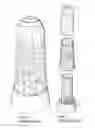
FIGS. 1 and 2 illustrate the prior art lamp 10 taught by U.S. Pat. No. 5,685,097. FIG. 1 (Prior Art) is a prior art lamp with opposing rotating images, and FIG. 2 (Prior Art) is an exploded view of the prior art lamp of FIG. 1.
As illustrated in attached FIGS. 1 and 2, a decorative lamp 10 having a base 12, top cap 20 and translucent housing 18. Sitting on the base within the housing are two overlapping opposing generally translucent film images 12 and 14. Within the base of the lamp 10 is a motor (not shown) which rotates the films about a lighting element 22 in opposing directions. The light 22 is positioned within the lamp behind the rotating films 12, 14 to illuminate the films. The prior art illustrated in FIGS. 1 and 2 is taught by U.S. Pat. No. 5,685,097.
One translucent member 12 is of a larger diameter than the other translucent member 14 such that one translucent member 12 may be placed around the other 14. In this manner, one film image 12 rotates in front of the other 14. As discussed previously, the prior art units are A/C powered devices.
FIG. 3 illustrates one example of light 300 of the present invention having improved function provided by the circuitry 400 illustrated in FIG. 4. The lamp 300 of FIG. 3 also includes all the following prior art components illustrated in FIGS. 1 & 2: base 310, top cap 320 and translucent housing 318. Like the lamp in FIGS. 1 & 2, the lamp 300, although not shown in FIG. 3, includes the two overlapping opposing rotating film images, a light positioned behind the films to illuminate the images and a motor to rotates the films about the light in opposing directions. Rather than being round or cylindrical, the lamp 300 of FIG. 3 has an oblong shaped to maximize the viewing area.
FIG. 4 is one example of a circuit 400 for controlling and powering the lamp 300 of the present invention. Unlike the prior art lamps, the lamp of FIG. 3 runs on a DC power supply that has a parallel power source 402 with a 1.5V C size alkaline battery capacity with about 7800 mAh. For example, six 1.5V C size batteries can be used. The lamp can also run on a 9V input voltage (6×1.5V) with a capacity of only 7800 mAh. In this application, a parallel circuit can be used to achieve two equal power sources 402 for the product in which each of them has an operation input voltage of, for example, 4.5V (3 pcs×1.5V), which can extend the service hours by twice (i.e. 15600 mAh.).
As illustrated in FIG. 4, two 4.5V battery power sources 402 are used to power the lamp 300. This parallel circuit for DC supply can be extended to two or more power sources 402 depending on the space availability of the product. For illustration, two sources 402 are shown.
As noted above, power sources 402 share the same voltage value (e.g. 4.5V per each) and the diodes D3 & D4 401 keep the voltages protected if either group of batteries voltage is lower than another. The circuit includes a microcontroller 404 (i.e., IC) for controlling the various operations of the lamp 300, as will described further below. The circuit further includes a motor 406 for controlling the operation/rotation of the films and LED (light emitting diode) lighting elements are provided at 408, which, in the illustrated example, are white LED lamps. While the circuit 400 shows the use of the two LED lighting elements 408, it would be possible to use one LED lighting element 408 or, conversely, more than two LED lighting elements 408.
Unlike the prior art, in the illustrated example of FIG. 4, an integrated circuit or microcontroller 404 is provided that can be programmed with different modes by one button where circulation can be used to increase the overall service-hours. In this way, using the programmed integrated circuit, different modes of operation may be provided. The following modes, for example, may be provided: (i) the animated film rotary and lighting element (e.g., LED) may work synchronously; (ii) the lighting element will only be on (with no animated film movement); and (iii) a shut off timer may be provided to shut of either or both the LED and the animated film rotary. It is also possible to provide for film rotation without the lamp; however, this mode is less desirable as the user will not have the effect of the transparent illuminated film. Since the design allows the selection of modes, power saving options are provided to the user to increase battery life and in service hours.
Further, the current design, use LED lighting, which does not require an electrical ballast that would be required for a compact fluorescent light bulb (“CFL”). The lamp 300 can simply be powered by DC supply and battery, like a common flashlight with direct battery connection. Further, the lamp 300 contains one bank for batteries thereby containing all of the circuitry in one compartment.
The foregoing description of an implementation has been presented for purposes of illustration and description. It is not exhaustive and does not limit the claimed invention to the precise form disclosed. Modifications and variations are possible in light of the above description or may be acquired from practicing the invention. The claims and their equivalents define the scope of the invention.
Claims
What is claimed is:1. A lamp comprising:
a base;
a translucent housing;
a top cap;
at least a first and second rotating film, where the second film is smaller than the first film and is placed within the circumference of, or behind, the first film;
a motor housed within the base for rotating the first and second firms in opposing directions;
an LED light source positioned behind the first and second firms for illuminating the films;
an integrated circuit; and
at least two DC power sources, where the lamp is powered by the two DC parallel power sources and controlled by the integrated circuit to enable the LED light sources and films to operate both simultaneously and independently of one another.
2. The lamp of claim 1 where the DC power sources are equal power sources.
3. The lamp of claim 1 where the integrated circuit further includes a timer for shutting off either or both the LED light source after a predetermined time as passed.
4. A lamp comprising:
a base;
a translucent housing;
a top cap;
at least a first and second rotating film, where the second film is smaller than the first film and is placed within the circumference of, or behind, the first film;
a motor housed within the base for rotating the first and second firms in opposing directions;
an LED light source positioned behind the first and second firms for illuminating the films;
an integrated circuit; and
at least two DC power sources, where the lamp is powered by the two DC parallel power sources and controlled by the integrated circuit having a timer that enables the following modes of operation of the lamp: (i) the powering on of both the motor and LED light source together; (ii) the powering of only the LED lighting element without the motor; and (iii) shutting off either or both the LED light source and motor after a predetermined time.
Images & Drawings included:


Sources:
- United States Patent and Trademark Office - verify current appl. status at the USPTO↗
Recent applications in this class:
- » 20250264208 2025-08-21
ARTIFICIAL SKYLIGHT DEVICE - » 20250216057 2025-07-03
LIGHT EMITTING MODULE - » 20250116391 2025-04-10
METHOD FOR ADJUSTING LIGHT-EMITTING ANGLE OF INDUSTRIAL AND MINING LAMP WITHOUT LIGHT LOSS - » 20250067419 2025-02-27
COATING FOR A FRAMING SHUTTER FOR A LUMINAIRE - » 20250012427 2025-01-09
Projection device with dynamic light effect - » 20250003576 2025-01-02
Improved hyperspectral light source - » 20240295306 2024-09-05
VARIABLE FROST SYSTEM - » 20240053664 2024-02-15
PROJECTION LAMP - » 20230194070 2023-06-22
Rotary type star projection lamp with audio playing and atmosphere set-off functions - » 20230112846 2023-04-13
Petal mechanism for light fixture
Recent applications for this Assignee:
- » 20240156676 2024-05-16
Cooling and heating massager - » 20230180967 2023-06-15
Shower Caddy - » 20230090085 2023-03-23
Cooling and heating massager - » 20220362097 2022-11-17
Percussion massager having a temperature-controlled massage node - » 20220362096 2022-11-17
Temperature-controlled massage node light indicator - » 20220211184 2022-07-07
Reversible ottoman - » 20190186705 2019-06-20
Flameless electronic candle - » 20180356816 2018-12-13
Drone with training mode - » 20180283633 2018-10-04
Flameless electronic candle - » 20180213954 2018-08-02
Two-sided pillow