Biometric sensors assembly for a hard hat
US20170000417A1
2017-01-05
15/259,406
2016-09-08
✅ Patent granted
US 9,642,574 B2
2017-05-09
-
-
Toan N Pham
Simonelli IP, PLLC
2036-09-08
Abstract:
A biometric sensor assembly measures biometric data of a wearer of a hardhat. The biometric sensor assembly includes a suspension harness to be removably secured to the hardhat. A biometric sensor is attached to the suspension harness in a way that allows direct or indirect contact with the wearer to enable measurement of the biometric data. The biometric sensor assembly also includes an electrical connection of the biometric sensor and the hardhat for data and power transmission.
Inventors:
- Saikat Dey 13 🇺🇸 Birmingham, MI, United States
- Gerrit Reepmeyer 7 🇺🇸 Novi, MI, United States
- Mikhail Zhavoronkov 14 🇺🇸 Northville, MI, United States
Assignee:
- Guardhat, Inc. 6 🇺🇸 Southfield, MI, United States
Applicant:
Interested in similar patents?
Get notified when new applications in this technology area are published.
Classification:
A42B3/324 » CPC further
Helmets; Helmet covers ; Other protective head coverings; Collapsible helmets; Helmets made of separable parts ; Helmets with movable parts, e.g. adjustable Adjustable helmets
A42B3/0433 » CPC further
Helmets; Helmet covers ; Other protective head coverings; Parts, details or accessories of helmets; Accessories for helmets Detecting, signalling or lighting devices
A61B5/6803 » CPC main
Measuring for diagnostic purposes ; Identification of persons; Arrangements of detecting, measuring or recording means, e.g. sensors, in relation to patient specially adapted to be attached to or worn on the body surface; Sensor mounted on worn items Head-worn items, e.g. helmets, masks, headphones or goggles
A61B5/486 » CPC further
Measuring for diagnostic purposes ; Identification of persons; Other medical applications Bio-feedback
A61B5/7455 » CPC further
Measuring for diagnostic purposes ; Identification of persons; Details of notification to user or communication with user or patient ; user input means characterised by tactile indication, e.g. vibration or electrical stimulation
A42B3/085 » CPC further
Helmets; Helmet covers ; Other protective head coverings; Parts, details or accessories of helmets; Chin straps or similar retention devices Occipital retention systems
A42B3/145 » CPC further
Helmets; Helmet covers ; Other protective head coverings; Parts, details or accessories of helmets; Linings; Suspension devices Size adjustment devices
A42B3/14 IPC
Helmets; Helmet covers ; Other protective head coverings; Parts, details or accessories of helmets; Linings Suspension devices
A42B3/08 IPC
Helmets; Helmet covers ; Other protective head coverings; Parts, details or accessories of helmets Chin straps or similar retention devices
A42B3/30 » CPC further
Helmets; Helmet covers ; Other protective head coverings; Parts, details or accessories of helmets Mounting radio sets or communication systems
A42B3/32 IPC
Helmets; Helmet covers ; Other protective head coverings Collapsible helmets; Helmets made of separable parts ; Helmets with movable parts, e.g. adjustable
A42B3/06 » CPC further
Helmets; Helmet covers ; Other protective head coverings; Parts, details or accessories of helmets Impact-absorbing shells, e.g. of crash helmets
G08B21/0453 » CPC further
Alarms responsive to a single specified undesired or abnormal condition and not otherwise provided for; Alarms for ensuring the safety of persons responsive to non-activity, e.g. of elderly persons; Sensor means for detecting worn on the body to detect health condition by physiological monitoring, e.g. electrocardiogram, temperature, breathing
A61B2503/20 » CPC further
Evaluating a particular growth phase or type of persons or animals Workers
A42B3/046 » CPC further
Helmets; Helmet covers ; Other protective head coverings; Parts, details or accessories of helmets; Accessories for helmets; Detecting, signalling or lighting devices Means for detecting hazards or accidents
H04Q9/00 » CPC further
Arrangements in telecontrol or telemetry systems for selectively calling a substation from a main station, in which substation desired apparatus is selected for applying a control signal thereto or for obtaining measured values therefrom
G08B21/04 IPC
Alarms responsive to a single specified undesired or abnormal condition and not otherwise provided for; Alarms for ensuring the safety of persons responsive to non-activity, e.g. of elderly persons
G08B23/00 IPC
Alarms responsive to unspecified undesired or abnormal conditions
A61B5/00 IPC
Measuring for diagnostic purposes ; Identification of persons
A42B3/04 IPC
Helmets; Helmet covers ; Other protective head coverings Parts, details or accessories of helmets
G08B21/02 » CPC further
Alarms responsive to a single specified undesired or abnormal condition and not otherwise provided for Alarms for ensuring the safety of persons
Description
This is a continuation-in-part of U.S. patent application having Ser. No. 15/150,384, filed May 9, 2016, which is a continuation-in-part of U.S. patent application having Ser. No. 14/883,157, filed Oct. 14, 2015, which is a divisional of U.S. Pat. No. 9,177,458, which is a divisional of U.S. Pat. No. 9,013,297, which was filed on Oct. 17, 2014.
BACKGROUND ART
1. Field of the Invention
The invention relates generally to the field of wearable devices. More particularly, the invention relates to wearable devices having sensors, including biometric sensors, attached thereto
2. Description of the Related Art
Helmets and other protectable wearables are often required when working in areas where there is a potential for injury. Helmets are especially required to protect the head from hazards such as impact from falling objects, scraping or bumping one's head on equipment, or contact with electrical conductors. Traditional suspension bands have been designed to extend inside the helmet and be used for spreading the helmet's weight and the force of any impact over the top of a user's head.
SUMMARY OF THE INVENTION
A biometric sensor assembly measures biometric data of a wearer of a hardhat. The biometric sensor assembly includes a suspension harness to be removably secured to the hardhat. A biometric sensor is attached to the suspension harness in a way that allows direct or indirect contact with the wearer to enable measurement of the biometric data. The biometric sensor assembly also includes an electrical connection of the biometric sensor and the hardhat for data and power transmission.
BRIEF DESCRIPTION OF THE DRAWINGS
Advantages of the invention will be readily appreciated as the same becomes better understood by reference to the following detailed description when considered in connection with the accompanying drawings, wherein:
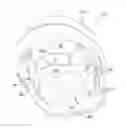
FIG. 1 is a perspective bottom view of the hard hat with electronics incorporated including the suspension band;
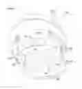
FIG. 2 is a perspective side view of the suspension band;
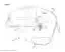
FIG. 3 is an exploded perspective view of the suspension band with sensors and a sweat band incorporated therein; and
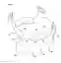
FIG. 4 is an exploded perspective view of an alternative embodiment of the invention.
DETAILED DESCRIPTION OF THE PREFERRED EMBODIMENT
FIG. 1 illustrates a hard hat, generally shown at 10, including an outer shell 12 and an adjustable suspension band assembly, generally indicated at 14. The suspension band assembly 14 extends around the interior 16 of the hard hat 10. The adjustable suspension band assembly 14 allows the user to adjustingly secure the outer shell 12 to the user's and to absorb energy from impacts and collisions via a connecting clip structure 27 that connects the suspension band assembly 14 with the outer shell 12 of the hard hat 10.
The adjustable suspension band 14 includes an adjusting device 20 that adjusts the diameter of a primary support loop 22. The suspension band including its electrical connection are described in greater detail in a U.S. patent application having Ser. No. 15/150,384, the disclosure of which is hereby incorporated by reference.
The hard hat 10 in FIG. 1 further includes a control unit 18 that may include electronic components and computing power to potentially enable electronic data processing capability locally within the hard hat 10. Also, the hard hat 10 may include a set of speakers 42 including corresponding volume buttons 44 to potentially enable audio communication within the hard hat 10 and a microphone (not shown) to capture audible signals/voices that are near the hard hat 10. In addition, the hard hat 10 could also include a light indicator 50 to provide visual feedback to the wearer.
The primary support loop 22 of the suspension band assembly 14 includes an electronic peripheral, which can take the form of a biometric sensors assembly 24 described in this patent in more detail later in FIGS. 3 and 4.
As shown in FIG. 2, the suspension band assembly 14 includes two attachment straps 26 that extend diametrically over the primary support loop 22 in a manner that provides enough slack to allow the head of the user to comfortably extend through the primary support loop 22. In some instances, the two attachment straps 26 may be adjustable to allow the user to have the two attachment straps 26 rest on the top of his or her head, providing more support and comfort.
An electrical anchor contact 28 is fixedly secured to the attachment strap 26 and provides an electrical connection between the hard hat 10 and the electronic peripheral as illustrated by the biometric sensors assembly 24 on the primary support loop 22. There may be more than one electrical anchor contact 28. Extending up from the electrical anchor contact 28 through the attachment strap 26 is an electrical conductor 30. The electrical conductor 30 completes the circuit between the biometric sensors assembly 24 in the primary support loop 22 and the control unit 18 that is attached to the outer shell 12 of the hard hat 10 (as shown in FIG. 1).
In FIG. 3, the setup of the biometric sensors assembly 24 is illustrated in more detail. As shown, the biometric sensors 32 are directly incorporated in the suspension band assembly 14. The biometric sensors 32 are electrically connected through the same electrical conductor 30 that connects the biometric sensors assembly 24 through the electrical anchor contact 28 with the control unit 18. This electrical connection ensures data and power transmission from the biometric sensors assembly 24 to the central control unit 18 and vice versa. The data connection will allow for processing the sensor data at the control unit 18.
The biometric sensors 32 can include any form of biometric sensor, such as for example, an optical heart rate monitor or a body temperature sensor. The suspension band assembly 14 might also include a haptic motor 48 to potentially provide haptic feedback to the wearer. The biometric sensors 32 and the haptic the motor 48 are usually covered by a cover or sweat band 34 that is placed over the suspension band assembly 14 and that encapsulates both the biometric sensors 32 and the haptic motor 48. The cover or sweat band 34 is forming the interface between the wearer's forehead and the biometric sensors 32 and/or the haptic motor 48. The cover or sweat band 34 should contain holes 36 at certain locations to allow the sensors to produce accurate sensor readings from the wearer's forehead. The cover or sweat band 34 is removable for cleaning purposes.
An alternative to directly incorporating the biometric sensors 32 into the suspension band assembly 14 and then using a cover or sweat band 34 to protect the sensors would be to include the biometric sensors 32 directly into an integrative band 46, is illustrated in FIG. 4. The integrative band 46 represents one assembly unit that combines a conductive pad 40 and a sweat band 34. The biometric sensors 32 and potentially a haptic motor 48 for providing haptic feedback to the wearer are placed on the conductive pad 40, thereby ensuring that the biometric sensors 32 and haptic motor 48 are positioned correctly and are connected to the electronic circuity of the hard hat 10.
The conductive pad 40 is connected directly with the control unit 18 through a physical connector 29 that might use a plug and play connection mechanism. The physical connector 29 will identify which biometric sensors 32 are on the suspension band assembly 14 and send that information directly to the control unit 18. The physical connector 29 ensures data and power transmission from the biometric sensors 32 and the haptic motor 48 to the central control unit 18 and vice versa. The flow of data will then enable processing of the sensor data.
The sweat band 34 is designed to fully enclose the biometric sensors 32 and the haptic motor 48. The sweat band 34 also contains holes 36 at certain locations to allow for the biometric sensors 32 to produce accurate sensor readings from the wearer's forehead.
The fully assembled integrative band 46 is attached to the suspension band assembly 14 in the same way as the cover or sweat band 34 in FIG. 3 by placing the integrative band 46 over the suspension band assembly 14.
With setup described in either FIG. 3 or FIG. 4, the biometric sensor assembly 24 is built in a way that it can provide for a warning mechanism that alerts the wearer via a certain notification system. For example, in case the central control unit 18 processes the data of the biometric sensors 32 and identifies that the measured biometric data of the wearer deviates significantly from a previously defined threshold, an audio message could be played to the wearer through the speaker set 42 (as illustrated in FIG. 1). The wearer will therefore immediately receive a respective warning if one of his or her biometrics shows a significant deviation. An alternative to an audio signal could be that the warning signal is being visualized to the wearer through a signaling light indicator 50 that is included in the hard hat 10, or that the wearer receives haptic feedback through a haptic motor 48 that is attached to the suspension band assembly 14.
The invention has been described in an illustrative manner. It is to be understood that the terminology, which has been used, is intended to be in the nature of words of description rather than of limitation.
Many modifications and variations of the invention are possible in light of the above teachings. Therefore, within the scope of the appended claims, the invention may be practiced other than as specifically described.
Claims
We claim:1. A biometric sensor assembly for measuring biometric data of a wearer of a hardhat, said biometric sensor assembly comprising:
a suspension harness to be removably secured to the hardhat;
a biometric sensor attached to said suspension harness in a way that allows direct or indirect contact with the wearer to enable measurement of the biometric data; and
an electrical connection of said biometric sensor and the hardhat for data and power transmission.
2. A biometric sensor assembly as set forth in claim 1 including a feedback mechanism that provides feedback to user.
3. A biometric sensor assembly as set forth in claim 1 including a haptic motor fixedly secured to said suspension harness allowing direct or indirect contact with body of the wearer to provide feedback to the wearer.
4. A biometric sensor assembly as set forth in claim 1 including a cover removably covering said biometric sensor and a portion of said suspension harness.
5. A biometric sensor assembly as set forth in claim 4 wherein said cover includes a hole disposed adjacent said biometric sensor to allow said biometric sensor to directly measure the biometric data.
6. A biometric sensor assembly for measuring biometric data of a wearer of a hardhat, said biometric sensor assembly comprising:
a suspension harness to be removably secured to the hardhat;
a conductive pad removably secured to said suspension harness;
a plurality of biometric sensors attached to said conductive pad in a way that allows direct or indirect contact with the wearer to enable measurement of the biometric data; and
an electrical connection of said plurality of biometric sensors and the hardhat for data and power transmission.
7. A biometric sensor assembly as set forth in claim 6 including a feedback mechanism that provides feedback to user.
8. A biometric sensor assembly as set forth in claim 6 including a haptic motor fixedly secured to said conductive pad allowing direct or indirect contact with body of the wearer to provide feedback to the wearer.
9. A biometric sensor assembly as set forth in claim 6 including a cover removably covering said conductive pad, said plurality of biometric sensors, and a portion of said suspension harness.
10. A biometric sensor assembly as set forth in claim 9 wherein said cover includes a hole disposed adjacent a portion of said plurality of said biometric sensors to allow each of said plurality of biometric sensors requiring direct measurement to function and to measure the biometric data.
11. A biometric sensor assembly as set forth in claim 6 wherein said electrical connection is a plug and play connection.
Images & Drawings included:
Sources:
- United States Patent and Trademark Office - verify current appl. status at the USPTO↗
Recent applications in this class:
- » 20250261906 2025-08-21
PHYSIOLOGICAL PARAMETER SENSOR HELMET - » 20250185993 2025-06-12
EEG MEASURING DEVICE - » 20250127455 2025-04-24
LENS FRAME FOR EYE EXAMINATION, METHOD FOR MEASURING NUMERICAL VALUE RELATING TO EYESIGHT, AND METHOD FOR DESIGNING SPECTACLE LENS - » 20250099034 2025-03-27
HEADSET FOR NEUROSTIMULATION AND SENSING OF BODY PARAMETERS - » 20250090093 2025-03-20
WEARABLE COMPUTING DEVICE - » 20250049393 2025-02-13
METHOD AND SYSTEM FOR A SMART MASK - » 20250032045 2025-01-30
CLASSIFYING FACIAL EXPRESSIONS USING EYE-TRACKING CAMERAS - » 20250025102 2025-01-23
MASK PROVIDING POSITIVE AIRWAY PRESSURE AND IMPEDANCE MEASUREMENT - » 20240407723 2024-12-12
WEARABLE APPARATUS FOR BRAIN SENSORS - » 20240407722 2024-12-12
EAR-WORN HEARING DEVICE WITH PHYSIOLOGICAL OR ACTIVITY SENSOR
Recent applications for this Assignee:
- » 20170289951 2017-10-05
Geo-localization assembly and methodology - » 20160213088 2016-07-28
Connection assembly for adjoining a peripheral with a host wearable device - » 20160110992 2016-04-21
Condition responsive indication assembly and method - » 20160106173 2016-04-21
Condition responsive indication assembly and method - » 15097833 2017-06-20
Assembly and method for calibrating a sensor on a wearable device