METHOD AND APPARATUS FOR SEPARATION AT SUBAMBIENT TEMPERATURE
US20170003073A1
2017-01-05
15/105,269
2014-12-19
Abstract:
A method for separating a gas mixture at subambient temperature, in which a gas mixture is sent to a heat-insulated chamber, cooled and separated in a column, and placed inside the chamber so as to produce at least two fluids, each of which is enriched with a component from the gas mixture. At least one fluid from the method can be heated inside the chamber or vaporized via heat exchange with at least one heating member including at least one element having magnetocaloric properties and built into a circuit configured to conduct a magnetic flux. The element is alternatingly in thermal contact with a cold source, made up of the fluid to be heated, and a hot source, made up of a source hotter than the fluid to be heated, and variation in the magnetic flux via the magnetocaloric effect generates electrical and/or mechanical energy.
Assignee:
Interested in similar patents?
Get notified when new applications in this technology area are published.
Classification:
F25J3/04278 » CPC main
Processes or apparatus for separating the constituents of gaseous or liquefied gaseous mixtures involving the use of liquefaction or solidification by rectification, i.e. by continuous interchange of heat and material between a vapour stream and a liquid stream for air; Generation of cold for compensating heat leaks or liquid production, e.g. by Joule-Thompson expansion using external refrigeration units, e.g. closed mechanical or regenerative refrigeration units
F25J3/04018 » CPC further
Processes or apparatus for separating the constituents of gaseous or liquefied gaseous mixtures involving the use of liquefaction or solidification by rectification, i.e. by continuous interchange of heat and material between a vapour stream and a liquid stream for air; Providing pressurised feed air or process streams within or from the air fractionation unit by compression of warm gaseous streams; details of intake or interstage cooling of main feed air
F25J3/04024 » CPC further
Processes or apparatus for separating the constituents of gaseous or liquefied gaseous mixtures involving the use of liquefaction or solidification by rectification, i.e. by continuous interchange of heat and material between a vapour stream and a liquid stream for air; Providing pressurised feed air or process streams within or from the air fractionation unit by compression of warm gaseous streams; details of intake or interstage cooling of purified feed air, so-called boosted air
F25J3/04157 » CPC further
Processes or apparatus for separating the constituents of gaseous or liquefied gaseous mixtures involving the use of liquefaction or solidification by rectification, i.e. by continuous interchange of heat and material between a vapour stream and a liquid stream for air; Purification and (pre-)cooling of the feed air; recuperative heat-exchange with product streams Afterstage cooling and so-called "pre-cooling" of the feed air upstream the air purification unit and main heat exchange line
F25J3/04187 » CPC further
Processes or apparatus for separating the constituents of gaseous or liquefied gaseous mixtures involving the use of liquefaction or solidification by rectification, i.e. by continuous interchange of heat and material between a vapour stream and a liquid stream for air; Purification and (pre-)cooling of the feed air; recuperative heat-exchange with product streams Cooling of the purified feed air by recuperative heat-exchange; Heat-exchange with product streams
F25J3/04412 » CPC further
Processes or apparatus for separating the constituents of gaseous or liquefied gaseous mixtures involving the use of liquefaction or solidification by rectification, i.e. by continuous interchange of heat and material between a vapour stream and a liquid stream for air using a dual pressure main column system in a classical double column flowsheet, i.e. with thermal coupling by a main reboiler-condenser in the bottom of low pressure respectively top of high pressure column
F25B21/00 » CPC further
Machines, plants or systems, using electric or magnetic effects
F25J3/0295 » CPC further
Processes or apparatus for separating the constituents of gaseous or liquefied gaseous mixtures involving the use of liquefaction or solidification by rectification, i.e. by continuous interchange of heat and material between a vapour stream and a liquid stream Start-up or control of the process; Details of the apparatus used, e.g. sieve plates, packings
F25J2200/06 » CPC further
Processes or apparatus using separation by rectification in a dual pressure main column system in a classical double column flow-sheet, i.e. with thermal coupling by a main reboiler-condenser in the bottom of low pressure respectively top of high pressure column
F25J2240/10 » CPC further
Processes or apparatus involving steps for expanding of process streams; Expansion of a process fluid in a work-extracting turbine (i.e. isentropic expansion), e.g. of the feed stream the fluid being air
F25J2220/40 » CPC further
Processes or apparatus involving steps for the removal of impurities Separating high boiling, i.e. less volatile components from air, e.g. CO, hydrocarbons
F25B2321/002 » CPC further
Details of machines, plants or systems, using electric or magnetic effects by using magneto-caloric effects
F25J2200/40 » CPC further
Processes or apparatus using separation by rectification Features relating to the provision of boil-up in the bottom of a column
F25J2270/908 » CPC further
Refrigeration techniques used; External refrigeration, e.g. conventional closed-loop mechanical refrigeration unit using Freon or NH, unspecified external refrigeration by regenerative chillers, i.e. oscillating or dynamic systems, e.g. Stirling refrigerator, thermoelectric ("Peltier") or magnetic refrigeration
F25J2220/82 » CPC further
Processes or apparatus involving steps for the removal of impurities; Separating impurities from carbon dioxide, e.g. HO or water-soluble contaminants Separating low boiling, i.e. more volatile components, e.g. He, H, CO, Air gases, CH
F25J2205/04 » CPC further
Processes or apparatus using other separation and/or other processing means using simple phase separation in a vessel or drum in the feed line, i.e. upstream of the fractionation step
F25J3/04 IPC
Processes or apparatus for separating the constituents of gaseous or liquefied gaseous mixtures involving the use of liquefaction or solidification by rectification, i.e. by continuous interchange of heat and material between a vapour stream and a liquid stream for air
F25J3/02 IPC
Processes or apparatus for separating the constituents of gaseous or liquefied gaseous mixtures involving the use of liquefaction or solidification by rectification, i.e. by continuous interchange of heat and material between a vapour stream and a liquid stream
Description
The present invention relates to a process and to an apparatus for separation at subambient temperature, or even cryogenic temperature. The separation may be separation by distillation and/or by dephlegmation and/or by absorption.
The separation is carried out using at least one column which, reduced in its simplest form, may be a phase separator.
Magnetic refrigeration is based on the use of magnetic materials which have a magnetocaloric effect. This effect, which is reversible, results in a variation in their temperature when they are subjected to the application of an external magnetic field. The optimum ranges within which these materials are used lie in the vicinity of their Curie temperature (Tc). This is because the greater the variations in magnetization and consequently in changes in magnetic entropy, the greater the changes in their temperature. The magnetocaloric effect is said to be direct when the temperature of the material increases when it is placed in a magnetic field, and indirect when it cools when it is placed in a magnetic field. The remainder of the description will be given for the direct case, but it is obvious to those skilled in the art how to reapply this to the indirect case. There are several similar dynamic cycles based on this principle. A conventional magnetic refrigeration cycle consists i) in magnetizing the material in order to increase the temperature thereof, ii) in cooling the material in a constant magnetic field in order to dissipate heat, iii) in demagnetizing the material in order to cool it, and iv) in heating the material in a constant (generally zero) magnetic field in order to absorb heat.
A magnetic refrigeration device uses elements made of magnetocaloric material, which generate heat when they are magnetized and absorb heat when they are demagnetized. It may use a magnetocaloric material regenerator in order to amplify the temperature difference between the “hot source” and the “cold source”: the magnetic refrigeration is then said to be magnetic refrigeration using active regeneration.
It is known practice to use the magnetocaloric effect to supply cold to a process for separating its subambient temperature in EP-A-2551005.
If the magnetocaloric materials are subjected to a temperature which varies, their magnetic conductivity varies. The optimum ranges within which these materials are used lie in the vicinity of their Curie temperature (Tc).
It is known practice, from “Simulation of a Thermomagnetic Motor using NiFe Alloy and Gd” by Alves et al., 5th International Conference on Magnetic Cold at Ambient Temperature, 2012, to convert heat into motive work and/or into electricity by modifying a magnetic field created by material which has a magnetocaloric effect. The modification of the field makes it possible to create motive work and/or an electric current.
Examples of electricity generators using a material which has a magnetocaloric effect using a cold source and a hot source are given in FR-A-2914503 and U.S. Pat. No. 8,453,466.
A heat pump is a thermodynamic device which makes it possible to transfer an amount of heat from a medium considered to be the “emitter” (supply medium), referred to as the “cold” source, to a heat “receiver” medium, referred to as the “hot” source. The cold source is the medium from which heat is extracted and the hot source is the medium into which the heat is reinjected, the cold source being at a temperature colder than the hot source.
The conventional cycle used in the prior art for this type of application is a thermodynamic cycle of compressing—cooling (condensing)—expanding—reheating (vaporizing) a refrigerating fluid.
An ambient temperature is the temperature of the ambient air in which the process is situated or, alternatively, a temperature of a cooling water circuit connected with the air temperature.
A subambient temperature is at least 10° C. below the ambient temperature.
A cryogenic temperature is below −20° C., or even below −55° C., or even below −100° C.
EP-A-2604824 describes a process according to the preamble of claim 1.
An objective of the present invention is to overcome all or some of the prior art drawbacks raised above.
An object of the present invention is to exploit the cold generated by the vaporization of a cryogenic liquid in a process for separation at subambient temperature.
According to one subject of the invention, a process is provided for separating a gas mixture at subambient temperature, or even cryogenic temperature, wherein a gas mixture is sent to a thermally insulated chamber, is cooled and is separated in a column, placed inside the chamber, so as to produce at least two fluids, each of which is enriched with a component of the gas mixture, at least one fluid from the process being heated inside the chamber, or even vaporized, by heat exchange with at least one heating member, characterized in that the at least one heating member comprises at least one element having magnetocaloric properties, and integrated into a circuit capable of conducting a magnetic flux, said at least one element being alternatingly in thermal contact with a cold source, made up of the fluid to be heated, or even the liquid to be vaporized, and a hot source made up of the surrounding environment or another source that is hotter than the fluid to be heated, and the variation in the magnetic flux via the magnetocaloric effect generates electrical and/or mechanical energy, the fluid to be heated being the gas mixture to be separated.
According to other optional aspects:
-
- the principle component(s) of the gas mixture is (are) at least one of the following fluids: air, nitrogen, oxygen, argon, carbon dioxide, methane, helium, hydrogen, carbon monoxide;
- the gas mixture contains at least 40 mol % of one of the following fluids: air, nitrogen, oxygen, argon, carbon dioxide, methane, helium, hydrogen, carbon monoxide;
- the gas mixture contains at least 60 mol % of one of the following fluids: air, nitrogen, oxygen, argon, carbon dioxide, methane, helium, hydrogen, carbon monoxide;
- the gas mixture contains at least 75 mol % of one of the following fluids: air, nitrogen, oxygen, argon, carbon dioxide, methane, helium, hydrogen, carbon monoxide;
- the main component(s) of the fluid to be heated is (are) at least one of the following fluids: air, nitrogen, oxygen, argon, carbon dioxide, methane, helium, hydrogen, carbon monoxide;
- the fluid to be heated contains at least 40 mol % of one of the following fluids: air, nitrogen, oxygen, argon, carbon dioxide, methane, helium, hydrogen, carbon monoxide;
- the fluid to be heated contains at least 60 mol % of one of the following fluids: air, nitrogen, oxygen, argon, carbon dioxide, methane, helium, hydrogen, carbon monoxide;
- the fluid to be heated contains at least 75 mol % of one of the following fluids: air, nitrogen, oxygen, argon, carbon dioxide, methane, helium, hydrogen, carbon monoxide;
- a fluid from the process is cooled by means of a cooling member comprising at least one element having magnetocaloric properties and integrated into a circuit capable of conducting a magnetic flux, said at least one element being alternatingly in thermal contact with a cold source, made up of the fluid to be cooled, or even a gas to be condensed, and a hot source made up of the surrounding environment or another source hotter than the fluid to be cooled;
- at least one fluid to be heated is at least one part of the gas mixture;
- at least one fluid to be heated is a fluid inside the column;
- at least one fluid to be heated is a fluid enriched with a component of the gas mixture originating from the column;
- the fluid to be heated is air withdrawn at an intermediate level of a heat exchanger serving to vaporize liquid oxygen and the heated air is sent back to an intermediate level of the heat exchanger in order to optimize the heat exchange;
- the fluid is a liquid;
- the fluid to be heated is brought into direct contact with the element having magnetocaloric properties;
- the heat exchange of the heating is carried out through a heat exchanger with a heat-transfer fluid having been in contact with the element having magnetocaloric properties;
- the heat exchange is carried out through an intermediate heat-transfer circuit with the heat-transfer fluid having been in contact with the element having magnetocaloric properties.
According to another subject of the invention, an apparatus is provided for separating a gas mixture at subambient temperature, or even cryogenic temperature, comprising a thermally insulated chamber, a heat exchanger and at least one separating column which are placed inside the chamber, a pipe for sending the gas mixture to the heat exchanger for it to cool, a pipe for sending the cooled mixture to the column, means for withdrawing at least two fluids, each of which is enriched with a component of the gas mixture from the column, a member for heating at least one fluid from the process, located inside the chamber, characterized in that the at least one heating member comprises at least one element having magnetocaloric properties and integrated into a circuit capable of conducting a magnetic flux, said at least one element being alternatingly in thermal contact with a cold source made up of the fluid to be heated, or even the liquid to be vaporized, and a hot source made up of the surrounding environment or another source that is hotter than the fluid to be heated and means for generating electrical and/or mechanical energy from the variation in the magnetic flux via the magnetocaloric effect, the fluid to be heated being the gas mixture to be separated.
According to other subjects of the invention:
-
- the column is a distillation and/or dephlegmation and/or absorption column;
- the column is a phase separator;
- the apparatus is an air separation apparatus;
- the apparatus is an apparatus for separating a gas mixture containing at least 40 mol % of one of the following fluids: air, nitrogen, oxygen, argon, carbon dioxide, methane, helium, hydrogen, carbon monoxide;
- the at least one separating column is a simple column having a top condenser and/or a bottom reboiler;
- the apparatus comprises a heating member comprising an element having magnetocaloric properties for heating the liquid of a bottom reboiler of the column;
- the apparatus comprises a cooling member comprising an element having magnetocaloric properties for cooling the top gas of a top condenser of the column;
- the heating member and/or the cooling member is/are placed inside the thermally insulated chamber.
The invention can also relate to any alternative device or process comprising any combination of the characteristics above or below.
Other particularities and advantages will emerge on reading the description hereinafter, given with reference to the figures in which:
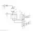
FIG. 1 represents a diagrammatic and partial view illustrating the structure and operation of a first example of a facility for producing gas according to the invention,
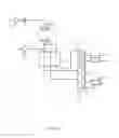
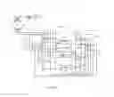
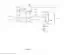
FIGS. 2 and 3 represent diagrammatic and partial views illustrating the structure and the operation of, respectively, a second and a third example of a facility for producing gas according to the invention.
FIG. 1 shows a process for separating air by cryogenic distillation. In this example, air 1 is compressed in a compressor 3, cooled in a cooler 5 to form a cooled flow 7 and purified in a purification unit 9. The purified air enters a thermally insulated chamber E and cools in a heat exchanger 17. The air cooled at a cryogenic temperature is sent to an intermediate level of a distillation column 23. The distillation column 23 is a simple column equipped with a top condenser 8 and with a bottom reboiler 10. The bottom reboiler 10 is heated by means of a heating member G comprising at least one element having magnetocaloric properties and integrated into a circuit capable of conducting a magnetic flux. The element is alternatingly in thermal contact with a cold source, made up of the liquid to be vaporized in the bottom of the column 23, through the reboiler 10, and a hot source made up of a fluid 4 hotter than the liquid to be vaporized. The variation in the magnetic flux via the magnetocaloric effect in the element generates electrical and/or mechanical energy. This therefore makes it possible either to generate electricity to be exported or to be used in the process, or to generate mechanical energy for driving, for example, a rotating machine of the process or a generator.
The cooling of the head of the column 23 may also be provided by a cooling member M comprising at least one element having magnetocaloric properties which serves to cool a top condenser 8 of the column. Thus, the gas of the top of the column constitutes the cold source of the cooling organ and the cold source is made up of the surrounding environment through a gas 2.
FIG. 2 shows an apparatus for separating air by cryogenic distillation. The apparatus comprises a heat exchange line 17 and a double air separation column comprising a medium-pressure column 23 and a low-pressure column 25 thermally connected by means of a reboiler 27.
Air 1 is compressed in a compressor 3 to a pressure of 5.5 bara. The compressed air is cooled in the cooler 5 so as to form a cooled flow 7 which is purified in order to remove the water and the carbon dioxide in an adsorption unit 9.
The purified air enters a thermally insulated chamber E and is divided up into four. A part 8A cools to an intermediate temperature of the heat exchanger 17, then is sent to a heating organ G comprising at least one element having magnetocaloric properties and integrated into a circuit capable of conducting a magnetic flux. The element is alternatingly in thermal contact with a cold source, made up of the air 8A at the intermediate temperature of the exchanger, and a cold source 4 made up of the surrounding environment or another source hotter than the air 8A. The variation in the magnetic flux via the magnetocaloric effect generates electrical and/or mechanical energy. The air 8A heated by the member G is sent back to the heat exchanger at a temperature higher than the temperature at which it is withdrawn therefrom. Use is made of the excess frigories available at the level of the oxygen vaporization plateau to produce a doubling of flow (of 8A) in the exchanger in order to try to absorb this cold as much as possible (by improving the exchange diagram), and to convert it into electrical energy.
A part 8B cools, while entirely passing through the exchange line 17, to a temperature of approximately −170° C. and is mixed with the flow 8A and then sent to the medium-pressure column in gas form. A part 8C cools while entirely passing through the exchange line 17 and then serves as a cold source for the heat pump 31 having a magnetocaloric effect. The remainder 21 is sent to separate a gas form in the column 23.
The part 8C cools and liquefies by heat exchange in the heat pump 31. The part 8C is divided up into a part 8D which is sent to the medium-pressure column 23 and a part 8E which is sent to the low-pressure column 25.
The invention could also apply to processes for separating other mixtures. For example in FIGS. 1 and 2, the air could be replaced with a mixture containing, as main components, methane and nitrogen and/or carbon dioxide.
A liquid enriched with oxygen 33 is withdrawn from the bottom of the medium-pressure column 23, cooled in the sub-cooler 43 and sent to the low-pressure column 25. A liquid enriched with nitrogen 35 is withdrawn from the top of the medium-pressure column 23, cooled in the sub-cooler 43 and sent to the top of the low-pressure column 25.
Air 11 is boosted in a booster 13, cooled in the exchange line 17, expanded in the turbine 15 and sent to the low-pressure column 25.
A nitrogen-rich gas 45 is withdrawn from the top of the low-pressure column 25, heated in the sub-cooler 43 and in the exchange line 17 and sent at least partly to the regeneration of the purification 9. Nitrogen-rich gas 49 is withdrawn from the top of the medium-pressure column 23, and heated in the exchange line 17 and serves as product. Liquid oxygen 47 is withdrawn from the low-pressure column 25, pressurized by a pump 29 and partially heated in the exchange line 17. The heated liquid is then removed from the exchange line 17, at least partially vaporized in the heat pump 31 and sent back to the exchange line 17, either for finishing the vaporization and heating, or solely for heating.
FIG. 3 illustrates a process for separating by distillation a carbon dioxide-rich gas mixture in order to produce a gas product enriched with carbon dioxide. A gas mixture 3 containing at least 60% of carbon dioxide and also at least one light impurity, which may be oxygen, carbon monoxide, nitrogen, argon, hydrogen or at least two of these constituents, is separated so as to form a fluid that is richer in carbon dioxide. The gas mixture comes from a source 1A which may be an oxycombustion unit followed by purification units in order to remove the water and other contaminants, such as dust, SOx or NOx. The source 1A may be a compressor. The gas mixture 3A is compressed as required for example at a pressure above 6 bar ABS. The pressurized gas mixture 3A is sent into a thermally insulated chamber E and is cooled in a brazed aluminum plate heat exchanger 5A. The cooled gas mixture is, as required, treated in a separating means 7A. This separating means 7A may be made up of a phase separator or several phase separators in series in order to increase the carbon dioxide content of the gas mixture upstream of the column 10A, for example in order to reach at least 80% of carbon dioxide for the liquid from a phase separator. The separating means 7A may alternatively or additionally comprise a distillation column, for example a column for removing NOx, or else an exchanger for at least partially cooling the gas mixture or a fluid derived from a part of the gas mixture.
The carbon dioxide-enriched liquid 9A is sent to the top of the low-temperature separating column 10A. The top gas 13A is withdrawn at the top of the column and is enriched with light components with respect to the liquid 9A. It heats in the exchanger 5A.
The bottom liquid contains more than 90% of carbon dioxide and is separated into three parts. A part 12A is sent to a heating member G comprising at least one element having magnetocaloric properties and integrated into a circuit capable of conducting a magnetic flux. The element is alternatingly in thermal contact with a cold source, made up of the liquid to be vaporized 12A, and a hot source 4A made up of the surrounding environment or another source that is hotter than the liquid 12A. The variation in the magnetic flux via the magnetocaloric effect generates electrical and/or mechanical energy. The heat produced by the member G makes it possible to vaporize the liquid 12A and the vaporized liquid is sent back to the bottom of the column 10A.
The remainder of the bottom liquid 11A is divided in two so as to form a part 15A and a part 19A. The part 15A is expanded in a valve 17A and vaporizes, then heats in the heat exchanger so as to form a carbon dioxide-rich gas product. The remainder 19A is sent to an intermediate level of the heat exchanger 5A, vaporizes therein and then heats so as to form a carbon dioxide-rich gas product, optionally combined with the first CO2-rich gas product, after compression, thereby forming the part 23A.
For all the figures, the variation in the magnetic flux via the magnetocaloric effect in the element can generate electrical energy to be exported or to be used in the process. Otherwise or additionally, the variation can generate mechanical energy for driving, for example, a rotating machine of the process or a generator.
Claims
1-15. (canceled)
16. A process for separating a gas mixture at subambient temperature, wherein the process comprises the steps of:
sending a gas mixture to a thermally insulated chamber under conditions effective for cooling and separating the gas mixture within a column that is placed inside the thermally insulated chamber, so as to produce at least two fluids, each of which is enriched with a component of the gas mixture;
heating at least one of the two fluids inside the thermally insulated chamber by heat exchange with at least one heating member, wherein the at least one heating member comprises at least one element having magnetocaloric properties and integrated into a circuit configured to conduct a magnetic flux, said at least one element being alternatingly in thermal contact with a cold source made up of the fluid to be heated and a hot source made up of the surrounding environment or another source that is hotter than the fluid to be heated; and
generating electrical and/or mechanical energy from the variation in the magnetic flux via the magnetocaloric effect,
wherein at least one of the two fluids to be heated being at least one part of the gas mixture.
17. The process as claimed in claim 16, wherein the main component(s) of the fluid to be heated is a fluid selected from the group consisting of air, nitrogen, oxygen, argon, carbon dioxide, methane, helium, hydrogen, carbon monoxide, and combinations thereof.
18. The process as claimed in claim 16, wherein at least one other fluid to be heated is a fluid inside the column.
19. The process as claimed in claim 16, wherein at least one other fluid to be heated is a fluid enriched with a component of the gas mixture originating from the column.
20. The process as claimed in claim 16, wherein the fluid is a liquid.
21. The process as claimed in claim 16, wherein the fluid to be heated is brought into direct contact with the element having magnetocaloric properties.
22. The process as claimed in claim 16, wherein the heat exchange of the heating is carried out through a heat exchanger with a heat-transfer fluid having been in contact with the element having magnetocaloric properties.
23. The process as claimed in claim 16, wherein the heat exchange is carried out through an intermediate heat-transfer circuit with the heat-transfer fluid having been in contact with the element having magnetocaloric properties.
24. An apparatus for separating a gas mixture at subambient temperature, or even cryogenic temperature, comprising a thermally insulated chamber, a heat exchanger and at least one separating column which are placed inside the chamber, a pipe for sending the gas mixture to the heat exchanger for it to cool, a pipe for sending the cooled mixture to the column, means for withdrawing at least two fluids, each of which is enriched with a component of the gas mixture from the column, at least one member for heating at least one fluid from the process, located inside the chamber, wherein the at least one heating member comprises at least one element having magnetocaloric properties and integrated into a circuit capable of conducting a magnetic flux, said at least one element being alternatingly in thermal contact with a cold source made up of the fluid to be heated, or even the liquid to be vaporized, and a hot source made up of the surrounding environment or another source that is hotter than the fluid to be heated and means for generating electrical and/or mechanical energy from the variation in the magnetic flux via the magnetocaloric effect, the fluid to be heated being the gas mixture to be separated.
25. The apparatus as claimed in claim 24, wherein the heating member and/or a cooling member for cooling a fluid from the process and comprising at least one element having magnetocaloric properties is/are placed inside the thermally insulated chamber.
26. The apparatus as claimed in claim 24, wherein the column is a phase separator.
27. The apparatus as claimed in claim 24, wherein the column is an air separation column.
28. The apparatus as claimed in claim 24, wherein the at least one separating column is a simple column having a top condenser and/or a bottom reboiler.
29. The apparatus as claimed in claim 24, comprising a heating member comprising an element having magnetocaloric properties for heating the liquid of a bottom reboiler of the column.
30. The apparatus as claimed in claim 24, comprising a cooling member comprising an element having magnetocaloric properties for cooling the top gas of a top condenser of the column.
Images & Drawings included:
Sources:
- United States Patent and Trademark Office - verify current appl. status at the USPTO↗
Recent applications in this class:
- » 20170211881 2017-07-27
METHOD AND SYSTEM FOR PROVIDING AUXILIARY REFRIGERATION TO AN AIR SEPARATION PLANT - » 20100281917 2010-11-11
Apparatus and Method for Condensing Contaminants for a Cryogenic System