Camera Lens
US20170010444A1
2017-01-12
15/060,242
2016-03-03
Abstract:
A camera lens includes, lined up from the object side to the image side, a first lens with positive refractive power, a second lens with negative refractive power, a third lens with negative refractive power, a fourth lens with positive refractive power, a fifth lens with positive refractive power, and a sixth lens with negative refractive power. The camera lens satisfies specific conditions.
Assignee:
- AAC ACOUSTIC TECHNOLOGIES (SHENZHEN) CO., LTD. 346 🇨🇳 Shenzhen, China
Interested in similar patents?
Get notified when new applications in this technology area are published.
Classification:
G02B13/0045 » CPC main
Optical objectives specially designed for the purposes specified below; Miniaturised objectives for electronic devices, e.g. portable telephones, webcams, PDAs, small digital cameras characterised by the lens design having at least one aspherical surface having five or more lenses
G02B27/0025 » CPC further
Optical systems or apparatus not provided for by any of the groups - for optical correction, e.g. distorsion, aberration
H04N5/2254 » CPC further
Details of television systems; Studio circuitry; Studio devices; Studio equipment ; Cameras comprising an electronic image sensor, e.g. digital cameras, video cameras, TV cameras, video cameras, camcorders, webcams, camera modules for embedding in other devices, e.g. mobile phones, computers or vehicles; Television cameras ; Cameras comprising an electronic image sensor, e.g. digital cameras, video cameras, camcorders, webcams, camera modules specially adapted for being embedded in other devices, e.g. mobile phones, computers or vehicles; Constructional details Mounting of optical parts, e.g. lenses, shutters, filters or optical parts peculiar to the presence or use of an electronic image sensor
G02B13/00 IPC
Optical objectives specially designed for the purposes specified below
G02B27/00 IPC
Optical systems or apparatus not provided for by any of the groups -
H04N5/225 IPC
Details of television systems; Studio circuitry; Studio devices; Studio equipment ; Cameras comprising an electronic image sensor, e.g. digital cameras, video cameras, TV cameras, video cameras, camcorders, webcams, camera modules for embedding in other devices, e.g. mobile phones, computers or vehicles Television cameras ; Cameras comprising an electronic image sensor, e.g. digital cameras, video cameras, camcorders, webcams, camera modules specially adapted for being embedded in other devices, e.g. mobile phones, computers or vehicles
G02B9/62 » CPC further
Optical objectives characterised both by the number of the components and their arrangements according to their sign, i.e. + or - having six components only
Description
FIELD OF THE INVENTION
The present disclosure is related to a camera lens, and more particularly to a camera lens comprising 6 lenses.
DESCRIPTION OF RELATED ART
In recent years, a variety of cameras equipped with CCD, CMOS or other camera elements are widely popular. Along with the development of miniature and high performance camera elements, the ultrathin and high-luminous flux (Fno) wide-angle camera lenses with excellent optical properties are needed in society.
The technology related to the camera lens composed of six ultra-thin, high-luminous flux f value (Fno) wide angle lenses with excellent optical properties is developed gradually. The camera lens mentioned in the proposal is composed of 6 lenses, lined up from the object side as follows: a first lens with positive refractive power, a second lens with negative refractive power, a third lens with negative refractive power, a fourth lens with positive refractive power, a fifth lens with positive refractive power, a sixth lens with negative refractive power.
The camera lens in embodiments 1 to 3 in the special published bulletin No. 2014-052631 is composed of 6 lenses described above, but the distribution of the refractive power of the second lens and the shape of the third lens are inadequate, therefore TTL/IH≧1.941, and ultrathin degree is not sufficient.
The camera lens disclosed in embodiments 1 to 3 of Japan patent document No. 5651881 is composed of 6 lenses, but, the distribution of the refractive power of the second lens and the third lens, the shape of the second lens are inadequate, therefore TTL/IH≧1.464 and ultrathin degree is not sufficient.
Therefore, it is necessary to provide a new camera lens to overcome the problems mentioned above.
BRIEF DESCRIPTION OF THE DRAWINGS
Many aspects of the embodiments can be better understood with reference to the following drawings. The components in the drawings are not necessarily drawn to scale, the emphasis instead being placed upon clearly illustrating the principles of the present disclosure. Moreover, in the drawings, like reference numerals designate corresponding parts throughout the several views.
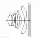
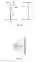
FIG. 1 is the structure diagram of a camera lens LA in the present invention.
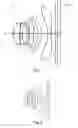
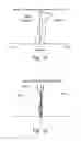
FIG. 2 is the structure diagram of a camera lens LA in the embodiment 1.
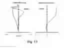
FIG. 3 is the diagram of the spherical aberration (axial chromatic aberration) of camera lens LA of embodiment 1 in the present invention.
FIG. 4 is the diagram of the magnification chromatic aberration of the camera lens LA in the embodiment 1.
FIG. 5 is the diagram of the image side curving and distortion aberration of the camera lens LA in the embodiment 1.
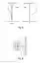
FIG. 6 is the structural diagram of the camera lens LA in the embodiment 2.
FIG. 7 is the diagram of the spherical aberration (axial chromatic aberration) of camera lens LA of embodiment 2 in the present invention.
FIG. 8 is the diagram of the magnification chromatic aberration of the camera lens LA in the embodiment 2.
FIG. 9 is the diagram of the image side curving and distortion aberration of the camera lens LA in the embodiment 2.
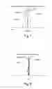
FIG. 10 is the structural diagram of the camera lens LA in the embodiment 3.
FIG. 11 is the diagram of the spherical aberration (axial chromatic aberration) of camera lens LA of embodiment 3 in the present invention.
FIG. 12 is the diagram of the magnification chromatic aberration of the camera lens LA in the embodiment 3.
FIG. 13 is the diagram of the image side curving and distortion aberration of camera lens LA of embodiment 3.
DESCRIPTION OF SYMBOLS
The camera lens LA of the present invention is described with the embodiments as follows. The symbols in all embodiments are represented as follows. In addition, the unit of the distance, radius and center thickness is mm.
- f: Overall focal distance of the camera lens LA
- f1: The focal distance of the first lens L1
- f2: The focal distance of the second lens L2
- f3: The focal distance of the third lens L3
- f4: The focal distance of the fourth lens L4
- f5: The focal distance of the fifth lens L5
- f6: The focal distance of the sixth lens L6
- Fno: F value
- 2ω: Total angle of view
- S1: Open aperture
- R: The curvature radius of the optical surface is the center curvature radius of lens.
- R1: The object side curvature radius of the first lens L1
- R2: The image side curvature radius of the first lens L1
- R3: The object side curvature radius of the second lens L2
- R4: The image side curvature radius of the second lens L2
- R5: The object side curvature radius of the third lens L3
- R6: The image side curvature radius of the third lens L3
- R7: The object side curvature radius of the fourth lens L4
- R8: The image side curvature radius of the fourth lens L4
- R9: The object side curvature radius of the fifth lens L5
- R10: The image side curvature radius of the fifth lens L5
- R11: The object side curvature radius of the sixth lens L6
- R12: The image side curvature radius of the sixth lens L6
- R13: The object side curvature radius of the glass plate GF
- R14: The image side curvature radius of glass plate GF
- d: The center thickness of lenses and the distance between lenses
- d 0: Distance from the open aperture Si to the object side of the first lens L1.
- d 1: The center thickness of the first lens L1
- d 2: The distance between the image side of the first lens L1 and the object
- side of the second lens L2.
- d 3: The center thickness of the second lens L2
- d 4: The axial distance between the image side of the second lens L2 and the
- object side of the third lens L3
- d 5: The center thickness of the third lens L3
- d 6: The axial distance between the image side of the third lens L3 and the object side of the fourth lens L4
- d 7: The center thickness of the fourth lens L4
- d 8: The axial distance between the image side of the fourth lens L4 and the object side of the fifth lens L5
- d 9: The center thickness of the fifth lens L5
- d 10: The axial distance between the image side of fifths lens L5 and the object side of sixth lens L6
- d 11: The center thickness of the sixth lens L6
- d 12: The axial distance between the image side of sixth lens L6 and the object side of the glass plate GF
- d 13: The center thickness of the glass plate GF
- d 14: The axial distance from the image side to the imaging plane of the glass plate GF
- n d: Refractive power of line d
- n d 1: Refractive power of line d of the first lens L1
- n d 2: Refractive power of line d of the second lens L2
- n d 3: Refractive power of line d of the third lens L3
- n d 4: Refractive power of line d of the fourth lens L4
- n d 5: Refractive power of line d of the fifth lens L5
- n d 6: The refractive power of line d of the sixth lens L6
- n d 7: Refractive power of line d of glass plate GF
- v: Abbe number
- v 1: Abbe number of the first lens L1
- v 2: Abbe number of the second lens L2
- v 3: Abbe number of the third lens L3
- v 4: Abbe number of the fourth lens L4
- v 5: Abbe number of the fifth lens L5
- v 6: Abbe number of the sixth lens L6
- v 7: Abbe number of the glass plate GF
- TTL: Optical length (the axial distance from the object side to the imaging plane of the first lens L1)
- LB: The axial distance from the image side to the imaging plane of the sixth lens L6 (including the thickness of the glass plate GF).
- IH: Image height
DETAILED DESCRIPTION OF THE EXEMPLARY EMBODIMENTS
The present invention will hereinafter be described in detail with reference to exemplary embodiments. To make the technical problems to be solved, technical solutions and beneficial effects of present disclosure more apparent, the present disclosure is described in further detail together with the figures and the embodiments. It should be understood the specific embodiments described hereby is only to explain this disclosure, not intended to limit this disclosure.
The camera lens in one embodiment of the present invention is explained with design drawings. FIG. 1 shows the structural diagram of one embodiment of the camera lens of the present invention. The camera lens LA is composed of 6 lenses which are lined up from the object side to the image side in turn as follows: an open aperture S1, a first lens L1, a second lens L2, a third lens L3, a fourth lens L4, a fifth lens L5 and a sixth lens L6. A glass plate GF is provided between the sixth lens L6 and the imaging plane. The glass plate GF is a glass cover or a light filter with IR cut-off filtration and other functions, or, the glass plate GF is not be provided between the lens L5 and the imaging plane.
The first lens L1 has positive refractive power. The second lens L2 has negative refractive power. The third lens L3 has negative refractive power. The fourth lens L4 has positive refractive power. The fifth lens L5 has positive refractive power. The sixth lens L6 has negative refractive power. In order to correct aberration better, the surface of six lenses is best designed to be non-spherical shape.
The camera lens LA satisfies the following specific conditions (1)-(4).
0.74≦f1/f≦0.85 (1)
−10.00≦f3/f≦−5.00 (2)
2.00≦(R3+R4)/(R3−R4)≦4.00 (3)
−4.00<(R5+R6)/(R5−R6)≦−2.00 (4)
In which,
- f: Overall focal distance of the camera lens
- f1: The focal distance of the first lens L1
- f3: The focal distance of the third lens L3
- R3: The object side curvature radius of the second lens L2
- R4: The image side curvature radius of the second lens L2
- R5: The object side curvature radius of the third lens L3
- R6: The image side curvature radius of the third lens L3
The condition (1) specifies the positive refractive power of the first lens L1. When exceeding the lower limit value of the condition (1), although in favor of the ultra-thin development of the lens, the first lens L1 has too big positive refractive power, and it is difficult to correct the aberration and other issues. On the contrary, when exceeding the upper limit, the first lens has too small positive refractive power, not conducive to the ultrathin development of lens. In addition, the limit of condition (1) is better set within the range of the condition (1-A) as follows.
0.76≦f1/f≦0.85 (1-A)
The condition (2) specifies the negative refractive power of the third lens L3. If exceeding the limit of the condition (2), along with Fno≦2.2 ultra-thin and wide-angle development of the lens, it is difficult to correct magnification chromatic aberration.
The condition (3) specifies the shape of the second lens L2. If exceeding the limit of the condition (3), along with Fno≦2.2 ultra-thin and wide-angle development of the lens, it is difficult to correct the axial chromatic aberration.
In addition, the limit of condition (3) is better set within the range of the condition (3-A) as follows.
2.10≦(R3+R4)/(R3−R4)≦3.65 (3-A)
The condition (4) specifies the shape of the third lens L3. If exceeding the limit of the condition (4), along with Fno≦2.2 ultra-thin and wide-angle development of the lens, it is difficult to correct magnification chromatic aberration.
In addition, the limit of condition (4) is better set within the range of the condition (4-A) as follows.
−4.00≦(R5+R6)/(R5−R6)≦−3.00 (4-A)
The first lens L1 has positive refractive power and satisfies the following condition (5).
−2.00≦f2/f≦−1.00 (5)
In which,
- f: Overall focal distance of the camera lens
- f2: The focal distance of the second lens L2.
The condition (5) specifies the negative refractive power of the second lens L2. If exceeding the limit of the condition (5), along with Fno≦2.2 ultra-thin and wide-angle development of the lens, it is difficult to correct the axial chromatic aberration.
The first lens L1 has positive refractive power and satisfies the following condition (6).
−1.55≦(R1+R2)/(R1−R2)≦−0.95 (6)
In which
- R1: The object side curvature radius of the first lens L1
- R2: The image side curvature radius of the first lens L1
The condition (6) specifies the shape of the first lens L1. If exceeding the limit of the condition (6), along with Fno≦2.2 ultra-thin and wide-angle development of the lens, it is difficult to correct the spherical aberration and other higher aberration issues.
As six lenses of the camera lens LA have the structure described previously and meet all conditions, the camera lens composed of six TTL (optical length)/IH (image height)≦1.45, ultrathin, wide-angle 2ω≧76°, high-luminous flux Fno≦2.2 lenses with excellent optical properties can be produced.
Embodiment
The camera lens LA of the present invention is described with the embodiments as follows. The symbols in all embodiments are represented as follows. In addition, the unit of the distance, radius and center thickness is mm.
- f: Overall focus distance of camera lens LA
- f1: The focal distance of the first lens L1
- f2: The focal distance of the second lens L2
- f3: The focal distance of the third lens L3
- f4: The focal distance of the fourth lens L4
- f5: The focal distance of the fifth lens L5
- f6: The focal distance of the sixth lens L6
- Fno: F value
- 2ω: Total angle of view
- S1: Open aperture
- R: The curvature radius of the optical surface is the center curvature radius of lens
- R1: The object side curvature radius of the first lens L1
- R2: The image side curvature radius of the first lens L1
- R3: The object side curvature radius of the second lens L2
- R4: The image side curvature radius of the second lens L2
- R5: The object side curvature radius of the third lens L3
- R6: The image side curvature radius of the third lens L3
- R7: The object side curvature radius of the fourth lens L4
- R8: The image side curvature radius of the fourth lens L4
- R9: The object side curvature radius of the fifth lens L5
- R10: The image side curvature radius of the fifth lens L5
- R11: The object side curvature radius of the sixth lens L6
- R12: The image side curvature radius of the sixth lens L6
- R13: The object side curvature radius of the glass plate GF
- R14: The image side curvature radius of glass plate GF
- d: The center thickness of lenses and the distance between lenses
- d 0: Distance from the open aperture Si to the object side of the first lens L1.
- d 1: The center thickness of the first lens L1
- d 2: The distance between the image side of the first lens L1 and the object side of the second lens L2.
- d 3: The center thickness of the second lens L2
- d 4: The axial distance between the image side of the second lens L2 and the object side of the third lens L3
- d 5: The center thickness of the third lens L3
- d 6: The axial distance between the image side of the third lens L3 and the object side of the fourth lens L4
- d 7: The center thickness of the fourth lens L4
- d 8: The axial distance between the image side of the fourth lens L4 and the object side of the fifth lens L5
- d 9: The center thickness of the fifth lens L5
- d 10: The axial distance between the image side of fifths lens L5 and the object side of sixth lens L6
- d 11: The center thickness of the sixth lens L6
- d 12: The axial distance between the image side of sixth lens L6 and the object side of the glass plate GF
- d 13: The center thickness of the glass plate GF
- d 14: The axial distance from the image side to the imaging plane of the glass plate GF
- n d: Refractive power of line d
- n d 1: Refractive power of line d of the first lens L1
- n d 2: Refractive power of line d of the second lens L2
- n d 3: Refractive power of line d of the third lens L3
- n d 4: Refractive power of line d of the fourth lens L4
- n d 5: Refractive power of line d of the fifth lens L5
- n d 6: The refractive power of line d of the sixth lens L6
- n d 7: Refractive power of line d of glass plate GF
- v: Abbe number
- v 1: Abbe number of the first lens L1
- v 2: Abbe number of the second lens L2
- v 3: Abbe number of the third lens L3
- v 4: Abbe number of the fourth lens L4
- v 5: Abbe number of the fifth lens L5
- v 6: Abbe number of the sixth lens L6
- v 7: Abbe number of the glass plate GF
- TTL: Optical length (the axial distance from the object side to the imaging plane of the first lens L1)
- LB: The axial distance from the image side to the imaging plane of the sixth lens L6 (including the thickness of the glass plate GF). IH: image height
y=(x2/R)/[1+{1−(k+1)(x2/R2)}1/2]+A4×4+A6×6+A8×8+A10×10+A12×12+A14×15+A16×16
In which, R is the axial curvature radius; k is the cone constant; A4, A6, A8, A10, A12, A14, A16 are aspherical coefficients.
As a matter of convenience, the aspheric surface of all lenses adopts the aspheric surface in condition (7). But not limited to the polynomial forms of the aspheric surface in condition (7).
Embodiment 1
FIG. 2 is the structure diagram of the camera lens LA of embodiment 1. The data in table 1 includes: The curvature radius R of the object side and the image side of the first lens L1 to the sixth lens L6 of the camera lens LA in embodiment 1, center thickness of the lenses or the distance D between lenses, refractive power nD, Abbe number v. The cone constant k and aspherical coefficient are shown in table 2.
| TABLE 1 | ||||
| R | d | nd | v d | |
| S1 | ∞ | d0= | −0.370 | ||||
| R1 | 1.76496 | d1= | 0.728 | nd1 | 1.5831 | v 1 | 59.39 |
| R2 | 8.67532 | d2= | 0.059 | ||||
| R3 | 8.52752 | d3= | 0.248 | nd2 | 1.6448 | v 2 | 22.44 |
| R4 | 3.28049 | d4= | 0.512 | ||||
| R5 | −5.19223 | d5= | 0.229 | nd3 | 1.6397 | v 3 | 23.53 |
| R6 | −6.93210 | d6= | 0.044 | ||||
| R7 | 13.25596 | d7= | 0.465 | nd4 | 1.5441 | v 4 | 56.12 |
| R8 | −42.16130 | d8= | 0.467 | ||||
| R9 | −4.88948 | d9= | 0.449 | nd5 | 1.5352 | v 5 | 56.12 |
| R10 | −1.56414 | d10= | 0.659 | ||||
| R11 | −3.49408 | d11= | 0.328 | nd6 | 1.5352 | v 6 | 56.12 |
| R12 | 2.99351 | d12= | 0.525 | ||||
| R13 | ∞ | d13= | 0.210 | nd7 | 1.5168 | v 6 | 64.17 |
| R14 | ∞ | d14= | 0.352 | ||||
| TABLE 2 | ||
| Cone Constant | Aspherical Coefficient |
| k | A4 | A6 | A8 | A10 | A12 | A14 | A16 | |
| R1 | −2.6457E−01 | 7.1806E−03 | 6.3309E−03 | −2.6993E−03 | 1.8000E−03 | −1.8153E−04 | 8.0948E−04 | −4.0201E−04 |
| R2 | 0.0000E+00 | −5.9373E−03 | −2.7016E−03 | 8.0058E−03 | 3.2154E−03 | −2.4778E−03 | −6.6869E−03 | 3.2767E−03 |
| R3 | −5.1420E+00 | −7.6154E−03 | 7.0223E−03 | 6.6977E−03 | 2.8608E−03 | −1.9035E−03 | −6.9415E−03 | 3.1617E−03 |
| R4 | −2.4752E−01 | 1.6986E−02 | 1.0499E−02 | 1.1448E−02 | 3.5142E−03 | 7.6755E−04 | 1.2648E−03 | 2.1145E−03 |
| R5 | 1.4945E+01 | −5.2018E−03 | −2.7645E−02 | 5.3154E−03 | 1.2701E−02 | 4.6451E−03 | −2.0111E−03 | 1.6147E−03 |
| R6 | 2.2863E+01 | −1.3414E−02 | −1.4755E−02 | 6.6927E−03 | 7.2883E−03 | 2.5651E−03 | −9.8356E−05 | −5.8412E−04 |
| R7 | 0.0000E+00 | −5.2967E−02 | 9.0012E−03 | 4.1528E−03 | 6.6717E−04 | −3.4350E−04 | −2.9085E−04 | 4.8092E−05 |
| R8 | 0.0000E+00 | −4.6841E−02 | 3.2202E−04 | 6.1492E−04 | −9.9929E−05 | 5.0849E−05 | 5.9897E−05 | 3.8758E−06 |
| R9 | 5.6021E+00 | −2.0491E−02 | −4.6875E−03 | 1.0712E−03 | −8.0078E−04 | −3.7298E−05 | 4.7146E−05 | 2.3196E−05 |
| R10 | −3.5973E+00 | −2.6378E−02 | 8.2036E−03 | −3.7951E−04 | 4.0294E−05 | −1.2623E−05 | −2.5586E−06 | −2.9441E−07 |
| R11 | 0.0000E+00 | 1.5123E−03 | 1.5066E−03 | 1.3873E−05 | −7.0564E−06 | −1.2349E−07 | 2.2066E−08 | 8.7553E−10 |
| R12 | −2.5742E+01 | −1.8468E−02 | 2.0437E−03 | −2.8494E−04 | 1.2543E−05 | 2.1677E−07 | −5.5634E−09 | 1.2351E−11 |
The values of the embodiments 1˜3 and the corresponding values of the parameters specified in the conditions (1)˜(6) are listed in table 7.
As shown in table 7, the embodiment 1 satisfies the conditions (1)-(6).
FIG. 3 is the diagram of the spherical aberration (axial chromatic aberration) of the camera lens LA in the embodiment 1. FIG. 4 is the diagram of the magnification chromatic aberration. FIG. 5 is the diagram of the image side curving and distortion aberration. In addition, the image side curving S in FIG. 5 is the image side curving relative to sagittal plane. T is the image side curving relative to the tangent plane. It is same also in embodiment 2 and 3. In embodiment 1, the camera lens LA with 2ω=78.1°, TTL/IH=1.409, Fno=2.05 ultra-thin, high-luminous flux wide-angle lenses, as shown in FIGS. 3-5, is easy to understand that it has excellent optical properties.
Embodiment 2
FIG. 6 is the structural diagram of the camera lens LA in the embodiment 2. The curvature radius R of the object side and image side of the first lens L1 to sixth lens L6, center thickness of the lenses and the distance d between the lenses, refractive power nd and Abbe number v of the camera lens LA in the embodiment 2 are shown in table 3. The cone constant k and aspherical coefficient are shown in table 4.
| TABLE 3 | ||||
| R | d | nd | v d | |
| S1 | ∞ | d0= | −0.250 | ||||
| R1 | 2.05855 | d1= | 0.667 | nd1 | 1.5831 | v 1 | 59.39 |
| R2 | −162.13476 | d2= | 0.053 | ||||
| R3 | 8.31674 | d3= | 0.246 | nd2 | 1.6448 | v 2 | 22.44 |
| R4 | 3.13480 | d4= | 0.526 | ||||
| R5 | −5.20424 | d5= | 0.238 | nd3 | 1.6397 | v 3 | 23.53 |
| R6 | −7.00949 | d6= | 0.048 | ||||
| R7 | 25.15081 | d7= | 0.443 | nd4 | 1.5441 | v 4 | 56.12 |
| R8 | −31.86314 | d8= | 0.469 | ||||
| R9 | −5.10336 | d9= | 0.400 | nd5 | 1.5352 | v 5 | 56.12 |
| R10 | −1.54692 | d10= | 0.745 | ||||
| R11 | −3.51704 | d11= | 0.334 | nd6 | 1.5352 | v 6 | 56.12 |
| R12 | 2.99421 | d12= | 0.525 | ||||
| R13 | ∞ | d13= | 0.210 | nd7 | 1.5168 | v 6 | 64.17 |
| R14 | ∞ | d14= | 0.367 | ||||
| TABLE 4 | ||
| Cone Constant | Aspherical Coefficient |
| k | A4 | A6 | A8 | A10 | A12 | A14 | A16 | |
| R1 | −3.9914E−01 | 5.1347E−03 | 3.9935E−03 | −4.3998E−03 | 7.0123E−04 | −9.0193E−04 | 3.1784E−04 | −7.5250E−04 |
| R2 | 0.0000E+00 | −3.4547E−03 | −1.5884E−03 | 7.8018E−03 | 2.5746E−03 | −3.1407E−03 | −7.1772E−03 | 2.9993E−03 |
| R3 | 7.2080E+00 | −5.3285E−03 | 9.2349E−03 | 8.4584E−03 | 4.0817E−03 | −1.1852E−03 | −6.5897E−03 | 3.2996E−03 |
| R4 | −1.0918E+00 | 1.3975E−02 | 1.7355E−03 | 5.8184E−03 | 6.3352E−04 | −4.7554E−04 | 8.5234E−04 | 2.0577E−03 |
| R5 | 1.5408E+01 | −6.2889E−03 | −2.7558E−02 | 5.0151E−03 | 1.2420E−02 | 4.4756E−03 | −2.2259E−03 | 1.3892E−03 |
| R6 | 2.0552E+01 | −1.2089E−02 | −1.4051E−02 | 6.9773E−03 | 7.3500E−03 | 2.5705E−03 | −8.6067E−05 | −5.6191E−04 |
| R7 | 0.0000E+00 | −5.3613E−02 | 9.0270E−03 | 4.2467E−03 | 6.8994E−04 | −4.1299E−04 | −3.0380E−04 | 6.8197E−05 |
| R8 | 0.0000E+00 | −4.7013E−02 | 4.6574E−04 | 7.8162E−04 | −1.0260E−05 | 7.6555E−05 | 5.2526E−05 | −9.8378E−06 |
| R9 | 5.6964E+00 | −2.0286E−02 | −4.8657E−03 | 9.9562E−04 | −8.2468E−04 | −4.4750E−05 | 4.4676E−05 | 2.2299E−05 |
| R10 | −3.4719E+00 | −2.6178E−02 | 8.3300E−03 | −3.3935E−04 | 5.1703E−05 | −9.4344E−06 | −1.6710E−06 | −5.0991E−08 |
| R11 | 0.0000E+00 | 1.5489E−03 | 1.5094E−03 | 1.4222E−05 | −7.0229E−06 | −1.1995E−07 | 2.2591E−08 | 9.9851E−10 |
| R12 | −2.2946E+01 | −1.8454E−02 | 2.0477E−03 | −2.8499E−04 | 1.2485E−05 | 2.0698E−07 | −6.8141E−09 | −1.3310E−10 |
As shown in table 7, the embodiment 2 satisfies the conditions (1)-(6).
FIG. 7 is the diagram of the spherical aberration (axial chromatic aberration) of the camera lens LA in the embodiment 2. FIG. 8 is the diagram of the magnification chromatic aberration. FIG. 9 is the diagram of the image side curving and distortion aberration. As shown in FIGS. 7-9, for full image angle 2ω=79.2°, TTL/IH=1.408, Fno=2.05 ultra-thin, high-luminous flux wide-angle lenses of the camera lens LA in the embodiment 2 are easy to understand that they have excellent optical properties.
Embodiment 3
FIG. 10 is the structural diagram of the camera lens LA in the embodiment 3. The curvature radius R of the object side and image side of the first lens L1 to sixth lens L6, center thickness of the lenses and the distance d between the lenses, refractive power nd and Abbe number v of the camera lens LA in the embodiment 3 are shown in table 5. The cone constant k and aspherical coefficient are shown in table 6.
| TABLE 5 | ||||
| R | d | nd | v d | |
| S1 | ∞ | d0= | −0.340 | ||||
| R1 | 1.85014 | d1= | 0.693 | nd1 | 1.5831 | v 1 | 59.39 |
| R2 | 12.98282 | d2= | 0.054 | ||||
| R3 | 8.21719 | d3= | 0.240 | nd2 | 1.6448 | v 2 | 22.44 |
| R4 | 3.08138 | d4= | 0.488 | ||||
| R5 | −5.14525 | d5= | 0.240 | nd3 | 1.6397 | v 3 | 23.53 |
| R6 | −7.31498 | d6= | 0.048 | ||||
| R7 | 11.73945 | d7= | 0.513 | nd4 | 1.5441 | v 4 | 56.12 |
| R8 | −11.59443 | d8= | 0.530 | ||||
| R9 | −4.60912 | d9= | 0.417 | nd5 | 1.5352 | v 5 | 56.12 |
| R10 | −1.59258 | d10= | 0.641 | ||||
| R11 | −3.44315 | d11= | 0.330 | nd6 | 1.5352 | v 6 | 56.12 |
| R12 | 2.90999 | d12= | 0.525 | ||||
| R13 | ∞ | d13= | 0.210 | nd7 | 1.5168 | v 6 | 64.17 |
| R14 | ∞ | d14= | 0.315 | ||||
| TABLE 6 | ||
| Cone Constant | Aspherical Coefficient |
| k | A4 | A6 | A8 | A10 | A12 | A14 | A16 | |
| R1 | −2.7852E−01 | 7.3839E−03 | 5.5077E−03 | −2.8976E−03 | 1.7625E−03 | −2.5232E−04 | 6.6166E−04 | −6.0391E−04 |
| R2 | 0.0000E+00 | −7.7522E−03 | −1.7226E−03 | 8.1227E−03 | 3.0129E−03 | −2.6824E−03 | −6.8245E−03 | 3.2187E−03 |
| R3 | −1.3156E+01 | −9.2638E−03 | 5.3509E−03 | 6.8432E−03 | 3.4362E−03 | −1.4272E−03 | −6.6749E−03 | 3.2726E−03 |
| R4 | −7.0467E−01 | 1.5119E−02 | 9.2835E−03 | 9.2141E−03 | 2.0401E−03 | 6.7868E−05 | 1.0864E−03 | 2.2099E−03 |
| R5 | 1.4708E+01 | −2.9712E−03 | −2.5768E−02 | 5.8409E−03 | 1.2638E−02 | 4.6549E−03 | −1.9855E−03 | 1.4996E−03 |
| R6 | 2.3219E+01 | −1.3800E−02 | −1.5386E−02 | 6.4132E−03 | 7.1404E−03 | 2.4223E−03 | −2.3378E−04 | −6.7842E−04 |
| R7 | 0.0000E+00 | −5.2888E−02 | 9.1069E−03 | 4.0982E−03 | 5.7745E−04 | −4.3429E−04 | −3.0353E−04 | 7.0333E−05 |
| R8 | 0.0000E+00 | −4.4853E−02 | 2.4082E−05 | 4.3692E−04 | −8.9891E−05 | 7.9119E−05 | 7.7391E−05 | 1.2703E−05 |
| R9 | 5.4730E+00 | −2.1679E−02 | −4.7642E−03 | 1.1528E−03 | −7.5970E−04 | −2.7027E−05 | 4.8647E−05 | 2.2901E−05 |
| R10 | −3.7237E+00 | −2.6449E−02 | 8.1111E−03 | −4.1930E−04 | 3.1869E−05 | −1.4001E−05 | −2.7097E−06 | −2.8304E−07 |
| R11 | 0.0000E+00 | 1.4508E−03 | 1.5112E−03 | 1.5098E−05 | −6.9538E−06 | −1.1876E−07 | 2.1807E−08 | 7.9746E−10 |
| R12 | −2.3465E+01 | −1.8288E−02 | 2.0952E−03 | −2.8188E−04 | 1.2541E−05 | 2.0988E−07 | −6.2247E−09 | −1.8842E−11 |
As shown in table 7, the embodiment 3 satisfies the conditions (1)-(6).
FIG. 11 is the diagram of the spherical aberration (axial chromatic aberration) of the camera lens LA in the embodiment 3. FIG. 12 is the diagram of the magnification chromatic aberration. FIG. 13 is the diagram of the image side curving and distortion aberration. In embodiment 3, the camera lens LA with 2ω=79.7°, TTL/IH=1.401, Fno=2.05 and ultra-thin, high-luminous flux and wide-angle lenses as shown in FIGS. 11-13 is easy to understand that it has excellent optical properties.
The values of the embodiments and the corresponding values of the parameters specified in conditions (1) to (7) are listed in table 7. In addition, the units in table 7 are 2ω(°), f(m m), f1(m m), f2(m m), f3(m m), f4(m m), f5(m m), f6(m m)TTL(m m), LB(m m), IH(m m).
| TABLE 7 | ||||
| Embod- | Embod- | |||
| iment 1 | iment 2 | Embodiment 3 | Condition | |
| f1/f | 0.803 | 0.785 | 0.822 | 1 |
| f3/f | −7.485 | −7.492 | −6.439 | 2 |
| (R3 + R4)/(R3 − R4) | 2.250 | 2.210 | 2.200 | 3 |
| (R5 + R6)/(R5 − R6) | −6.969 | −6.766 | −5.743 | 4 |
| f2/f | −1.850 | −1.789 | −1.770 | 5 |
| (R1 + R2)/(R1 − R2) | −1.511 | −0.975 | −1.332 | 6 |
| Fno | 2.05 | 2.05 | 2.05 | |
| 2ω | 78.1 | 79.2 | 79.7 | |
| TTL/IH | 1.409 | 1.408 | 1.401 | |
| f | 4.554 | 4.445 | 4.401 | |
| f1 | 3.658 | 3.491 | 3.617 | |
| f2 | −8.425 | −7.951 | −7.789 | |
| f3 | −34.088 | −33.300 | −28.338 | |
| f4 | 18.590 | 25.904 | 10.805 | |
| f5 | 4.104 | 3.991 | 4.338 | |
| f6 | −2.690 | −2.969 | −2.894 | |
| TTL | 5.275 | 5.271 | 5.244 | |
| LB | 1.087 | 1.102 | 1.050 | |
| IH | 3.744 | 3.744 | 3.744 | |
It is to be understood, however, that even though numerous characteristics and advantages of the present embodiments have been set forth in the foregoing description, together with details of the structures and functions of the embodiments, the disclosure is illustrative only, and changes may be made in detail, especially in matters of shape, size, and arrangement of parts within the principles of the invention to the full extent indicated by the broad general meaning of the terms in which the appended claims are expressed.
Claims
What is claimed is:1. A camera lens comprising, lined up from the object side to the image side, a first lens with positive refractive power, a second lens with negative refractive power, a third lens with negative refractive power, a fourth lens with positive refractive power, a fifth lens with positive refractive power, and a sixth lens with negative refractive power; wherein
the camera lens has satisfies the following conditions (1)-(4):
0.74≦f1/f≦0.85 (1)
−10.00≦f3/f≦−5.00 (2)
2.00≦(R3+R4)/(R3−R4)≦4.00 (3)
−4.00<(R5+R6)/(R5−R6)≦−2.00 (4)
In which,
f: Overall focal distance of the camera lens;
f1: The focal distance of the first lens L1;
f3: The focal distance of the third lens L3;
R3: The object side curvature radius of the second lens L2;
R4: The image side curvature radius of the second lens L2;
R5: The object side curvature radius of the third lens L3;
R6: The image side curvature radius of the third lens L3.
2. The camera lens according to claim 1 further satisfying the following condition (5):
−2.00≦f2/f≦−1.00 (5)
In which
f: Overall focal distance of the camera lens;
f2: The focal distance of the second lens L2.
3. The camera lens according to claim 1 further satisfying the following condition (6):
−1.55≦(R1+R2)/(R1−R2)≦−0.95 (6)
In which,
R1: The object side curvature radius of the first lens L1;
R2: The image side curvature radius of the first lens L1.
Images & Drawings included:

Sources:
- United States Patent and Trademark Office - verify current appl. status at the USPTO↗
Similar patent applications:
- » 20200150388
Camera lens processing method, camera lens, camera assembly and electronic device - » 20130250109
Multi-lens camera system, vehicle mounting the multi-lens camera system, and range-finding method executed by the multi-lens camera system - » 20210088757
Multi-lens camera lens, camera module, and terminal including a lens providing a diffractive surface concave to the image side plane - » 20240118459
MOTOR FOR DRIVING LIQUID STATE CAMERA LENS, CAMERA LENS ASSEMBLY, AND TERMINAL DEVICE - » 20180231737
Camera lens, camera and method of locking a focus ring in a camera lens - » 20240244309
CAMERA LENS MODULE, CAMERA LENS OPTICAL AXIS ADJUSTING DEVICE, AND BINOCULAR CAMERA - » 20190129073
CAMERA LENS AND CAMERA LENS ASSEMBLY HAVING SAME - » 20190243093
Camera lens assembly and camera device equipped with camera lens assembly - » 20180292628
Camera lens assembly and camera device equipped with camera lens assembly - » 20210033820
Camera lens assembly and camera device comprising the camera lens assembly
Recent applications in this class:
- » 20250172789 2025-05-29
IMAGING LENS AND IMAGING APPARATUS - » 20250172788 2025-05-29
OPTICAL IMAGING SYSTEM - » 20250172787 2025-05-29
OPTICAL LENS, CAMERA MODULE, AND TERMINAL DEVICE - » 20250172786 2025-05-29
OPTICAL LENS ASSEMBLY - » 20250164757 2025-05-22
OPTICAL IMAGING SYSTEM - » 20250164756 2025-05-22
LENS ASSEMBLY AND ELECTRONIC DEVICE COMPRISING SAME - » 20250164755 2025-05-22
OPTICAL SYSTEM - » 20250164754 2025-05-22
OPTICAL IMAGING SYSTEM AND MOBILE ELECTRONIC DEVICE - » 20250164753 2025-05-22
OPTICAL SYSTEM - » 20250164752 2025-05-22
OPTICAL IMAGING LENS
Recent applications for this Assignee:
- » 20250126386 2025-04-17
MEMS microphone - » 20250080917 2025-03-06
Speaker module and assembling method thereof - » 20250038713 2025-01-30
Single-end-to-differential microphone circuit - » 20250024199 2025-01-16
Microphone amplifying circuit design method and microphone amplifying circuit - » 20240212464 2024-06-27
Vibration control method, vibration control device, and non-transitory computer-readable storage medium - » 20240194037 2024-06-13
Motion-sensing in-vehicle alerting method, system and related device - » 20240171913 2024-05-23
Sealed dual membrane structure and device including the same - » 20240107239 2024-03-28
MEMS optical microphone - » 20240089654 2024-03-14
Method and apparatus for eliminating sound leakage - » 20240087555 2024-03-14
Method and apparatus for eliminating sound leakage