Ultrasound probe
US20170014866A1
2017-01-19
15/211,019
2016-07-15
✅ Patent granted
US 10,399,120 B2
2019-09-03
-
-
Bryan P Gordon
2037-05-25
Abstract:
An ultrasound probe including a matching element, a backing layer, a piezoelectric element and a driver is provided. The piezoelectric element is disposed between the matching element and the backing layer. The driver generates a coding wave inputted to the piezoelectric element, such that the piezoelectric element outputs a focusing sonic wave field along a short axis.
Assignee:
- QISDA Corporation 367 🇹🇼 Taoyuan, Taiwan
- Qisda Corporation 275 🇹🇼 Taoyuan City, Taiwan
Applicant:
Interested in similar patents?
Get notified when new applications in this technology area are published.
Classification:
H01L41/042 » CPC further
Piezo-electric devices in general; Electrostrictive devices in general; Magnetostrictive devices in general; Processes or apparatus specially adapted for the manufacture or treatment thereof or of parts thereof; Details thereof; Details of piezo-electric or electrostrictive devices Drive or control circuitry or methods for piezo-electric or electrostrictive devices not otherwise provided for
H02N2/001 » CPC further
Electric machines in general using piezo-electric effect, electrostriction or magnetostriction producing non-specific motion; Details common to machines covered by - Driving devices, e.g. vibrators
H01L41/09 » CPC further
Piezo-electric devices in general; Electrostrictive devices in general; Magnetostrictive devices in general; Processes or apparatus specially adapted for the manufacture or treatment thereof or of parts thereof; Details thereof; Piezo-electric or electrostrictive devices with electrical input and mechanical output, e.g. actuators, vibrators
H02N2/00 IPC
Electric machines in general using piezo-electric effect, electrostriction or magnetostriction
H01L41/04 IPC
Piezo-electric devices in general; Electrostrictive devices in general; Magnetostrictive devices in general; Processes or apparatus specially adapted for the manufacture or treatment thereof or of parts thereof; Details thereof; Details of piezo-electric or electrostrictive devices
B06B1/0215 » CPC main
Methods or apparatus for generating mechanical vibrations of infrasonic, sonic, or ultrasonic frequency making use of electrical energy; Driving circuits for generating pulses, e.g. bursts of oscillations, envelopes
A61B8/4461 » CPC further
Diagnosis using ultrasonic, sonic or infrasonic waves; Constructional features of the ultrasonic, sonic or infrasonic diagnostic device related to the probe Features of the scanning mechanism, e.g. for moving the transducer within the housing of the probe
G01N29/2437 » CPC further
Investigating or analysing materials by the use of ultrasonic, sonic or infrasonic waves; Visualisation of the interior of objects by transmitting ultrasonic or sonic waves through the object; Details, e.g. general constructional or apparatus details; Probes Piezoelectric probes
B06B1/02 IPC
Methods or apparatus for generating mechanical vibrations of infrasonic, sonic, or ultrasonic frequency making use of electrical energy
G01N29/2456 » CPC further
Investigating or analysing materials by the use of ultrasonic, sonic or infrasonic waves; Visualisation of the interior of objects by transmitting ultrasonic or sonic waves through the object; Details, e.g. general constructional or apparatus details; Probes Focusing probes
B06B2201/55 » CPC further
Indexing scheme associated with for details covered by but not provided for in any of its subgroups; Application to a particular transducer type Piezoelectric transducer
B06B2201/76 » CPC further
Indexing scheme associated with for details covered by but not provided for in any of its subgroups; Specific application Medical, dental
G01N2291/02475 » CPC further
Indexing codes associated with group; Indexing codes associated with the analysed material; Mixtures Tissue characterisation
A61B8/00 IPC
Diagnosis using ultrasonic, sonic or infrasonic waves
G01N29/24 IPC
Investigating or analysing materials by the use of ultrasonic, sonic or infrasonic waves; Visualisation of the interior of objects by transmitting ultrasonic or sonic waves through the object; Details, e.g. general constructional or apparatus details Probes
G01N29/34 IPC
Investigating or analysing materials by the use of ultrasonic, sonic or infrasonic waves; Visualisation of the interior of objects by transmitting ultrasonic or sonic waves through the object Generating the ultrasonic, sonic or infrasonic waves, e.g. electronic circuits specially adapted therefor
G01N29/348 » CPC further
Investigating or analysing materials by the use of ultrasonic, sonic or infrasonic waves; Visualisation of the interior of objects by transmitting ultrasonic or sonic waves through the object; Generating the ultrasonic, sonic or infrasonic waves, e.g. electronic circuits specially adapted therefor with frequency characteristics, e.g. single frequency signals, chirp signals
Description
This application claims the benefit of Taiwan application Serial No. 104123046, filed Jul. 16, 2015, the subject matter of which is incorporated herein by reference.
BACKGROUND OF THE INVENTION
Field of the Invention
The invention relates in general to an ultrasound probe, and more particularly to an ultrasound probe capable of generating a focusing sonic wave field.
Description of the Related Art
Normally, the ultrasound probe uses an acoustic lens to complete the focusing in a short axis to detect the tissue of an analyte. The acoustic lens is normally formed of a room temperature vulcanized silicone rubber (RTV). Since materials of the same kind are subject to high attenuation, it has become a prominent task for the industries to provide a new method for focusing in a short axis.
SUMMARY OF THE INVENTION
The invention is directed to an ultrasound probe enabling the piezoelectric element to receive a coding wave to output a focusing sonic wave field along a short axis.
According to one embodiment of the present invention, an ultrasound probe is provided. The ultrasound probe includes a matching element, a backing layer, a piezoelectric element and a driver. The piezoelectric element is disposed between the matching element and the backing layer. The driver generates a coding wave inputted to the piezoelectric element, such that the piezoelectric element outputs a focusing sonic wave field along a short axis.
According to another embodiment of the present invention, an ultrasound probe is provided. The ultrasound probe includes a matching element, a backing layer, a piezoelectric element and a driver. The piezoelectric element is disposed between the matching element and the backing layer and has a variable thickness along a short axis. The driver generates an adjustable coding wave inputted to the piezoelectric element, such that the piezoelectric element outputs a focusing sonic wave field correspondingly modulated according to the adjustment of the coding wave and the thickness of the piezoelectric element.
According to an alternate embodiment of the present invention, an ultrasound probe is provided. The ultrasound probe includes a matching element, a backing layer, a piezoelectric element and a driver. The piezoelectric element is disposed between the matching element and the backing layer. The matching element does not have any acoustic lenses disposed thereon, and the driver generates a wave signal inputted to the piezoelectric element, such that the piezoelectric element outputs a focusing sonic wave field along a short axis.
The above and other aspects of the invention will become better understood with regard to the following detailed description of the preferred but non-limiting embodiment (s). The following description is made with reference to the accompanying drawings.
BRIEF DESCRIPTION OF THE DRAWINGS
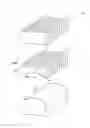
FIG. 1 is a decomposition diagram of an ultrasound probe according to an embodiment of the invention;
FIG. 2 is an assembly diagram of the ultrasound probe of FIG. 1; and
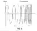
FIG. 3 is a waveform of a coding wave according to an embodiment of the invention.
DETAILED DESCRIPTION OF THE INVENTION
Refer to FIGS. 1-3. FIG. 1 is a decomposition diagram of an ultrasound probe 100 according to an embodiment of the invention. FIG. 2 is an assembly diagram of the ultrasound probe 100 of FIG. 1. FIG. 3 is a waveform of a coding wave P1 according to an embodiment of the invention.
The ultrasound probe 100 includes a plurality of matching elements 110, a backing layer 120, a plurality of piezoelectric elements 130 and a driver 140.
The matching elements 110 may be made of material including epoxy mixing sliver powders, epoxy mixing aluminum oxide powders, etc. The matching elements 110 and ultrasound gel have an impedance in between that of the piezoelectric elements 130 and skin of a patient to reduce the amount of reflection at this interface and accordingly improve transmission into the patient.
The backing layer 120 may be made of material including polyurethane (PU), epoxy mixing tungsten powders, epoxy mixing carbon fibers, etc. The backing layer 120 can provide an effect on widening the bandwidth.
The piezoelectric element 130 has a concave surface 103s1 and a plane 130s2 disposed oppositely. The concave surface 103s1 can be a curved surface, a plane or a combination thereof. The curved surface can be a circular curved surface, an elliptic curved surface or a curved surface with other geometric shape. The plane 130s2 faces a detecting direction (exemplified by the +Z axis in the present embodiment), that is, the direction towards the analyte 10, and the concave surface 130s1 backs to the detecting direction (the −Z axis). The backing layer 120 has a convex surface 120s1 matching the concave surface 130s1 of the piezoelectric element 130.
The piezoelectric element 130 is disposed between the matching element 110 and the backing layer 120. Each piezoelectric element 130 has an edge portion 131 and a middle portion 132.
The driver 140, such as a coding-wave driver, generates a coding wave P1 inputted to the piezoelectric element 130, such that the piezoelectric element 130 outputs a focusing sonic wave field W1 along a short axis S1 (as indicated in FIG. 2). The short axis S1 is a direction moving towards the middle portion 132 from the edge portion 131, and is substantially perpendicular to a long axis S2. The long axis S2 is the arrangement direction of a plurality of piezoelectric elements 130. The ultrasound probe 100 detects the properties of the analyte 10 through the focusing sonic wave field W1. The analyte 10 can be a living tissue (such as human or animal) or a non-living tissue.
In addition, the piezoelectric element 130 has a variable thickness t along a short axis S1 and correspondingly generates the focusing sonic wave field W1. That is, the field pattern of the focusing sonic wave field W1 varies with the thickness t of the piezoelectric element 130 along the short axis S1, such that different focusing sonic wave fields W1 can be used to detect different tissue portions or varieties. As indicated in FIG. 2, the focusing sonic wave field W1 has a focal spot W11 whose position varies with the thickness t of the piezoelectric element 130 along the short axis S1.
As indicated in FIG. 1, the thickness t2 of the middle portion 132 is smaller than the thickness t1 of the edge portion 131. For example, the thickness t of the piezoelectric element 130 diminishes in a direction towards the middle portion 132 from the edge portion 131. As indicated in FIG. 3, the coding wave P1 includes a high frequency wave-pattern P11 and a low frequency wave-pattern P12. The time sequence of the coding wave P1 is that the low frequency wave-pattern P12 comes before the high frequency wave-pattern P11. That is, the time sequence inputted to the piezoelectric element 130 is: low frequency wave-pattern P12 to high frequency wave-pattern P11, which means the low frequency signal enters the piezoelectric element 130 earlier than the high frequency signal. After entering the piezoelectric element 130, the low frequency signal resonates with the thicker portion and is transmitted outwards, and the high frequency signal resonates with the thinner portion and is transmitted outwards. Thus, the focusing sonic wave field W1 is generated.
Let FIG. 2 be taken for example. Since the time sequence of the coding wave P1 is that the low frequency wave-pattern P12 comes before the high frequency wave-pattern P11, the low frequency wave-pattern P12 enters the piezoelectric element 130 earlier than the high frequency wave-pattern P11. After entering the piezoelectric element 130, the low frequency wave-pattern P12 resonates with the thicker portion, that is, the edge portion 131, and then is transmitted towards the +Z axis; the high frequency wave-pattern P11 resonates with the thinner portion, that is, the middle portion 132, and then is transmitted towards the +Z axis. Regarding the time sequence by which the signal is transmitted outwards from the piezoelectric element 130, the low frequency wave-pattern P12 in the edge portion 131 with a larger thickness is transmitted outwards earlier than the high frequency wave-pattern P11 in the edge portion 131 with a larger thickness so as to generate the focusing sonic wave field W1. Here, the Z axis is basically perpendicular to the short axis S1 and the long axis S2, and the direction of the Z axis faces towards the analyte 10.
In addition, the coding wave P1 is adjustable, such that the piezoelectric element 130 can output a focusing sonic wave field W1 correspondingly modulated according to the adjustment of the coding wave P1. The field pattern of the focusing sonic wave field W1 and/or the position of the focusing sonic wave field W1 can be changed according to the adjustment. To put it in greater details, when the high frequency wave-pattern P11 and/or the frequency, amplitude and/or cycle of the low frequency wave-pattern P12 changes, the field pattern of the focusing sonic wave field W1 and/or the position of the focal spot W11 will change accordingly. For example, the focal spot W11 becomes farther away from or closer to the piezoelectric element 130 along the direction of the Z axis.
In an embodiment, the coding wave P1 can be a chirp coding wave, a barker coding wave, or a Golay coding wave. The coding wave P1 can be expressed in formula (1). In formula (1),
g ( t - T 2 )
represents a Gauss function; f1 represents a low frequency signal frequency; f2 represents a high frequency signal frequency; T represents a signal cycle.
P 1 = g ( t - T 2 ) cos ( 2 π ( f 1 t + f 2 - f 1 2 T t 2 ) ) ( 1 )
The piezoelectric element 130 can output a focusing sonic wave field W1 correspondingly modulated according to the design of the coding wave P1 and/or the thickness of the piezoelectric element 130 along the short axis S, such that the conventional acoustic lens can be dispensed with. That is, the matching element 110 does not need to have any acoustic lenses disposed thereon. In other words, the ultrasound probe 100 of the embodiment of the invention can be an ultrasound probe without having any acoustic lenses.
It can be understood from the above disclosure that the piezoelectric element 130 can output a focusing sonic wave field W1 correspondingly modulated according to the design of the coding wave P1 and/or the thickness of the piezoelectric element 130 to detect different varieties of tissues. Since the focusing sonic wave field W1 is outputted along the short axis S1, the ultrasound probe 100 of the embodiment of the invention can selectively dispense with the conventional acoustic lens.
While the invention has been described by way of example and in terms of the preferred embodiment(s), it is to be understood that the invention is not limited thereto. On the contrary, it is intended to cover various modifications and similar arrangements and procedures, and the scope of the appended claims therefore should be accorded the broadest interpretation so as to encompass all such modifications and similar arrangements and procedures.
Claims
What is claimed is:1. An ultrasound probe, comprising:
a matching element;
a backing layer;
a piezoelectric element disposed between the matching element and the backing layer; and
a driver;
wherein the driver generates a coding wave, wherein the coding wave is inputted to the piezoelectric element, such that the piezoelectric element outputs a focusing sonic wave field along a short axis.
2. The ultrasound probe according to claim 1, wherein the piezoelectric element comprises an edge portion and a middle portion, the piezoelectric element has a thickness diminishing in a direction towards the middle portion from the edge portion.
3. The ultrasound probe according to claim 2, wherein the coding wave comprises a high frequency wave-pattern and a low frequency wave-pattern, and the time sequence of the coding wave changes to the high frequency wave-pattern from the low frequency wave-pattern.
4. The ultrasound probe according to claim 1, wherein the matching element does not have any acoustic lenses disposed thereon.
5. The ultrasound probe according to claim 1, wherein the focusing sonic wave field has a focal spot whose position varies with the coding wave.
6. The ultrasound probe according to claim 1, wherein the coding wave is adjustable, such that the piezoelectric element outputs a focusing sonic wave field correspondingly modulated according to the adjustment of the coding wave.
7. The ultrasound probe according to claim 1, wherein the driver is a coding-wave driver.
8. An ultrasound probe, comprising:
a matching element;
a backing layer;
a piezoelectric element disposed between the matching element and the backing layer and having a variable thickness along a short axis; and
a driver;
wherein the driver generates an adjustable coding wave inputted to the piezoelectric element, such that the piezoelectric element outputs a focusing sonic wave field correspondingly modulated according to the adjustment of the coding wave and the thickness of the piezoelectric element.
9. The ultrasound probe according to claim 8, wherein the piezoelectric element comprises a middle portion and an edge portion, and the middle portion has a thickness smaller than that of the edge portion.
10. The ultrasound probe according to claim 8, wherein the piezoelectric element has a concave surface and a plane, and the concave surface and the plane are opposite to each other.
11. The ultrasound probe according to claim 8, wherein the coding wave comprises a low frequency wave-pattern and a high frequency wave-pattern, and both the low frequency wave-pattern and the high frequency wave-pattern are adjustable.
12. The ultrasound probe according to claim 8, wherein the coding wave comprises a high frequency wave-pattern and a low frequency wave-pattern, the time sequence of the coding wave changes to the high frequency wave-pattern from the low frequency wave-pattern.
13. The ultrasound probe according to claim 8, comprising a plurality of piezoelectric elements arranged along a long axis, each piezoelectric element has a thickness changing along a short axis, and the focusing sonic wave field is emitted towards a detecting direction substantially perpendicular to the long axis and the short axis.
14. The ultrasound probe according to claim 8, wherein the piezoelectric element has a concave surface backing to a detecting direction.
15. The ultrasound probe according to claim 8, wherein the piezoelectric element has a concave surface, the backing layer has a convex surface matching the concave surface.
16. The ultrasound probe according to claim 8, wherein the piezoelectric element comprises an edge portion and a middle portion, the piezoelectric element has a thickness diminishing towards the middle portion from the edge portion.
17. An ultrasound probe, comprising:
a matching element;
a backing layer;
a piezoelectric element disposed between the matching element and the backing layer; and
a driver;
wherein the matching element does not have any acoustic lenses disposed thereon, and the driver generates a wave signal inputted to the piezoelectric element, such that the piezoelectric element outputs a focusing sonic wave field along a short axis.
18. The ultrasound probe according to claim 17, wherein the piezoelectric element comprises a middle portion and an edge portion, and the middle portion has a thickness smaller than that of the edge portion.
19. The ultrasound probe according to claim 17, wherein the coding wave comprises a high frequency wave-pattern and a low frequency wave-pattern, and the time sequence of the wave signal changes to the high frequency wave-pattern from the low frequency wave-pattern.
20. The ultrasound probe according to claim 17, wherein the driver is a coding-wave driver.
Images & Drawings included:


Sources:
- United States Patent and Trademark Office - verify current appl. status at the USPTO↗
Similar patent applications:
- » 20220327735
ULTRASOUND PROBE POSITION REGISTRATION METHOD, ULTRASOUND IMAGING SYSTEM, ULTRASOUND PROBE POSITION REGISTRATION SYSTEM, ULTRASOUND PROBE POSITION REGISTRATION PHANTOM, AND ULTRASOUND PROBE POSITION REGISTRATION PROGRAM - » 20230263508
METHOD FOR DRIVING AN ULTRASOUND PROBE, ULTRASOUND PROBE AND ULTRASOUND SYSTEM COMPRISING SAID ULTRASOUND PROBE - » 20210007718
Ultrasound probe, control method of ultrasound probe, and ultrasound probe inspection system - » 20230014965
Wireless ultrasound probe using wirelessly supplied power, ultrasound diagnosis apparatus wirelessly connected to wireless ultrasound probe, operating method of ultrasound diagnosis apparatus, and operating method of wireless ultrasound probe - » 20200100767
Wireless ultrasound probe using wirelessly supplied power, ultrasound diagnosis apparatus wirelessly connected to wireless ultrasound probe, operating method of ultrasound diagnosis apparatus, and operating method of wireless ultrasound probe - » 20140323861
Wireless ultrasound probe using wirelessly supplied power, ultrasound diagnosis apparatus wirelessly connected to wireless ultrasound probe, operating method of ultrasound diagnosis apparatus, and operating method of wireless ultrasound probe - » 20190365352
Wireless ultrasound probe, ultrasound diagnostic apparatus connected to wireless ultrasound probe, and operating method of ultrasound diagnostic apparatus - » 20220133272
Wireless ultrasound probe, ultrasound diagnostic apparatus connected to wireless ultrasound probe, and operating method of ultrasound diagnostic apparatus - » 20240335179
WIRELESS ULTRASOUND PROBE, ULTRASOUND DIAGNOSTIC APPARATUS CONNECTED TO WIRELESS ULTRASOUND PROBE, AND OPERATING METHOD OF ULTRASOUND DIAGNOSTIC APPARATUS - » 20140221841
Ultrasound probe, ultrasound diagnostic imaging apparatus and manufacturing method of ultrasound probe
Recent applications in this class:
- » 20250178028 2025-06-05
ULTRASONIC TRANSMITTING CIRCUIT, ULTRASONIC IMAGING APPARATUS, AND METHOD FOR GENERATING EXCITATION SIGNAL - » 20250121407 2025-04-17
Method and Device for Driving a Beamforming Ultrasound Transducer Array, and Corresponding System - » 20250058352 2025-02-20
POWER SUPPLY DEVICE FOR PUSH WAVE GENERATION - » 20250025915 2025-01-23
ELECTRONIC DEVICE AND METHOD FOR OPERATING RESONATOR ELEMENT AT RESONANCE FREQUENCY - » 20250018426 2025-01-16
ACOUSTIC CLEAVING APPARATUS AND METHODS OF ACOUSTIC CLEAVING - » 20240416384 2024-12-19
PULSE SHAPING METHODS FOR NON-LINEAR ACOUSTIC PIEZOELECTRIC TRANSDUCERS - » 20240165664 2024-05-23
METHOD FOR DRIVING A WAVE EMITTER AND RECEIVER DEVICE - » 20240165663 2024-05-23
Capacitive micromachined ultrasonic transducer with contoured electrode - » 20240109101 2024-04-04
METHOD FOR DRIVING A TRANSMITTING DEVICE - » 20240050986 2024-02-15
ULTRASOUND TRANSMITTER
Recent applications for this Assignee:
- » 20250295036 2025-09-18
Flexible Ultrasonic Transducer and Flexible Ultrasonic Transducer Module - » 20250279077 2025-09-04
DISPLAY AND DISPLAY MANUFACTURING METHOD - » 20250277661 2025-09-04
THREE DIMENSIONAL SCANNING APPARATUS - » 20250274146 2025-08-28
Wireless transmission module for an unmanned aerial vehicle - » 20250273978 2025-08-28
POWER CONTROL METHOD AND RELATED ELECTRONIC DEVICE - » 20250254283 2025-08-07
STEREOSCOPIC SCANNING DEVICE AND STEREOSCOPIC SCANNING METHOD - » 20250251536 2025-08-07
STEREOSCOPIC SCANNING DEVICE AND STEREOSCOPIC SCANNING METHOD - » 20250251236 2025-08-07
STEREOSCOPIC SCANNING DEVICE AND STEREOSCOPIC SCANNING METHOD - » 20250251108 2025-08-07
ILLUMINATION SYSTEM - » 20250244653 2025-07-31
PROJECTION DEVICE