ADJUSTING DIMENSIONING RESULTS USING AUGMENTED REALITY
US20170017301A1
2017-01-19
14/801,023
2015-07-16
Abstract:
A system and method for using an augmented reality interface to adjust the results from a dimensioning system are disclosed. The augmented reality interface allows users to easily correct dimensioning errors, improve dimensioning results, and guide dimensioning analysis. In one embodiment, the user may adjust/select the results via hand gesturing/positioning within the system's field of view. In another embodiment, the user may use virtual tools, enabled by hand gesturing/positioning, to adjust the results. In still another embodiment, the user may shine a light into the system's field of view to adjust the results. The augmented reality interface embraced by the present invention provides the user with an easier, more-intuitive means for interacting with dimensioning system results.
Inventors:
- Jeffrey Mark Hunt 9 🇺🇸 Kirkland, WA, United States
- Tyler Doornenbal 2 🇺🇸 Bothell, WA, United States
- Sanjaya Bandaragoda 2 🇺🇸 Mukilteo, WA, United States
Interested in similar patents?
Get notified when new applications in this technology area are published.
Classification:
G06F3/017 » CPC main
Input arrangements for transferring data to be processed into a form capable of being handled by the computer; Output arrangements for transferring data from processing unit to output unit, e.g. interface arrangements; Input arrangements or combined input and output arrangements for interaction between user and computer Gesture based interaction, e.g. based on a set of recognized hand gestures
G06T19/006 » CPC further
Manipulating 3D models or images for computer graphics Mixed reality
G06F3/01 IPC
Input arrangements for transferring data to be processed into a form capable of being handled by the computer; Output arrangements for transferring data from processing unit to output unit, e.g. interface arrangements Input arrangements or combined input and output arrangements for interaction between user and computer
G06T19/00 IPC
Manipulating 3D models or images for computer graphics
Description
FIELD OF THE INVENTION
The present invention relates to dimensioning systems and more specifically, to a means for adjusting the results from dimensioning systems using augmented reality.
BACKGROUND
Many applications require non-contact, three-dimensional (3D) scanning of objects. An object may be scanned remotely without the need to touch the object. Active 3D scanners project radiation (e.g., light, ultrasound, X-ray, etc.) into a field of view and detect the radiation reflected from an object. A time-of-flight 3D scanner, for example, projects pulse of light onto an object and measures the time taken for the pulse of light to reflect from the object and return to the range finder. In another example, a structured light 3D scanner projects a light pattern (e.g., a dot pattern of light) onto an object, while a camera, offset from the projector, captures an image of the reflected pattern. The projector and camera may use triangulation to determine a range for each of the dots in the reflected dot pattern of light.
Dimensioning systems (i.e., dimensioners) may use 3D scanners (i.e., 3D sensors) to determine the dimensions (e.g., surface length, surface area, and object volume) of an object. These systems have found use in the transport and logistics industries. For example, dimensioning systems may facilitate the calculation of shipping cost based on package volume. In another example, dimensioning systems may help form packing strategies for transportation and/or storage.
During the dimensioning process, feedback may provide a user a way of verifying that the 3D scanner has scanned an object correctly. This feedback may include an image of the object overlaid with graphics showing the results of the 3D scan. For example, a package may have its edges highlighted by an overlaid wireframe graphic.
Dimensioning systems may return errors. For example, shading and/or glare could cause the dimensioning system to determine an edge of an object erroneously. In this case, the feedback would include a wireframe that did not align with the object's true edge. A human might easily see this misalignment in the feedback image and could help adjust the wireframe to fit the edges, thereby improving the results from the dimensioner.
Wireframe manipulation maybe difficult using traditional touch displays because using a 2D display to manipulate an object in three dimensions can easily result in errors. For example, an intended adjustment along one axis could cause an unwanted adjustment in another axis because it is difficult for a user to decouple height/width from depth using a 2D display.
Therefore, a need exists for an augmented reality interface to allow a user to (i) correct dimensioning errors, (ii) improve dimensioning results, and (iii) guide dimensioning analysis. The augmented reality interface embraced by the present invention provides the user with an easier, more-intuitive means for interacting with a dimensioning system.
SUMMARY
Accordingly, in one aspect, the present invention embraces a dimensioning system. The dimensioning system includes a three-dimensional (3D) sensor for measuring the dimensions of objects (i.e., dimensioning) in a field of view. The dimensioning system also includes a camera for capturing real-time images of the objects. The dimensioning system further includes a processor that is communicatively coupled to the 3D Sensor, the camera, and a display. The processor is configured to create augmented-reality feedback that is displayed, in real-time, to a user via the display. The augmented-reality feedback includes the real-time images captured by the camera and graphic elements that are overlaid on the real-time images. Gestures in the real-time images are recognized by the processor and the graphic elements are adjusted in response.
In an exemplary embodiment of the dimensioning system, the gestures include a hand gesture.
In another exemplary embodiment of the dimensioning system, the gestures include the position and/or motion of a point of light projected into the field of view and reflected from the objects in the field of view.
In another exemplary embodiment of the dimensioning system, the graphic elements include wireframes that correspond to the edges of the objects in the field of view.
In another exemplary embodiment of the dimensioning system, the graphic elements include wireframes and virtual tools for adjusting and/or selecting the wireframes.
In another exemplary embodiment of the dimensioning system, the graphic elements include wireframes and virtual tools. The virtual tools include a tweezer for grabbing an edge of the wireframes, a pointer for selecting a face of the wireframes, and/or a virtual hand for grabbing the wireframes.
In another exemplary embodiment of the dimensioning system, the graphic elements include wireframes and the adjustment of the graphic elements includes selecting a portion of the wireframes for dimensioning.
In another exemplary embodiment of the dimensioning system, the graphic elements include wireframes and the adjustment of the graphic elements includes rotating and/or translating the wireframes.
In another aspect, the present invention embraces an augmented reality interface for a dimensioning system. The interface includes a camera for capturing images of a field of view that is aligned with the dimensioning system's field of view. The interface also includes a display for displaying images and graphical information to a user. A processor is communicatively coupled to the camera, the display, and the dimensioning system. The processor is configured by software to receive images from the camera and to receive dimensioning information, corresponding to an object in the dimensioning system's field of view, from the dimensioner. Using the dimensioning information, the processor is configured to create wireframe graphics that correspond to the edges of the object. The images and the wireframe graphics are presented on the display, wherein the wireframe graphics overlay and are aligned with the object. The processor is further configured to recognize adjustment cues in the images and to adjust the wireframe graphics in response to the adjustment cues.
In an exemplary embodiment of the augmented reality interface, the processor is further configured to update the dimensioning information in response to the adjustment of the wireframe graphics. The processor is also configured to communicate this updated wireframe information to the dimensioning system.
In another exemplary embodiment of the augmented reality interface, the adjustment cues include a user's hand reaching into the field of view and virtually manipulating the wireframe graphics presented on the display.
In another exemplary embodiment of the augmented reality interface, the adjustment cures include a light spot projected into the field of view to select a surface indicated by the wireframe graphics presented on the display.
In another exemplary embodiment of the augmented reality interface, the adjustment to the wireframe graphics includes resizing the wireframe graphics.
In another exemplary embodiment of the augmented reality interface, the adjustment to the wireframe graphics includes rotating and/or translating the wireframe graphics.
In another exemplary embodiment of the augmented reality interface, the adjustment to the wireframe graphics includes deleting a portion of the wireframe graphics.
In another exemplary embodiment of the augmented reality interface, the adjustment to the wireframe graphics includes combining wireframe graphics.
In another aspect, the present invention embraces a method for correcting dimensioning errors using an augmented reality interface. The method begins with the step of observing the results from a dimensioning system, wherein the results are displayed as virtual wireframes overlaid on real-time images of objects in a field of view. The virtual wireframes correspond to the edges of one or more surfaces on one or more objects in the dimensioning system's field of view. Errors in the virtual wireframes are identified. A hand is then reached into the dimensioning system's field of view so that it is displayed with the objects and the virtual wireframes. One of the virtual wireframes is selected using a virtual tool enabled by the hand or by using the hand itself. The selected virtual wireframe is then adjusted by moving the hand or the virtual tool. The steps of (i) identifying errors in the virtual wireframes, (ii) reaching into the field of view, (iii) selecting one of the virtual wireframes, and (iv) adjusting the selected virtual wireframe is repeated until all of the errors in the virtual wireframes have been corrected.
In an exemplary method for correcting dimensioning errors using an augmented reality interface, the errors in the virtual wireframes include (i) virtual wireframes that overlap, (ii) virtual wireframes that cover more than one object, and/or (iii) virtual wireframes that do not cover an object completely.
In another exemplary method for correcting dimensioning errors using an augmented reality interface, the augmented reality interface is an optical head-mounted display worn by a user.
The foregoing illustrative summary, as well as other exemplary objectives and/or advantages of the invention, and the manner in which the same are accomplished, are further explained within the following detailed description and its accompanying drawings.
BRIEF DESCRIPTION OF THE DRAWINGS
FIG. 1 graphically depicts a perspective view of a user adjusting the output of a dimensioning system using an augmented reality interface according to an exemplary embodiment of the present invention.
FIG. 2 graphically depicts an image from an augmented reality interface showing a user manipulating a virtual tool to interact with the results from a dimensioning system according to an exemplary embodiment of the present invention.
FIG. 3 graphically depicts an image from an augmented reality interface showing a user manipulating a projected laser beam to interact with the results from a dimensioning system according to an exemplary embodiment of the present invention.
FIG. 4 schematically depicts a block diagram of a dimensioning system according to an embodiment of the present invention.
FIG. 5 schematically depicts a block diagram of an augmented reality interface for a dimensioning system according to an embodiment of the present invention.
FIG. 6 depicts a flowchart of a method for correcting dimensioning errors using an augmented reality interface according to an embodiment of the present invention.
DETAILED DESCRIPTION
Dimensioning systems are convenient tools to obtain dimensional information (e.g., volume, area of a side, etc.) about an object automatically and remotely (i.e., non-contact). The output from these systems may include images of the object and its environment. These images may also include graphics that add context to dimensioning results. For example, wireframe graphics (i.e., wireframes, virtual wireframes, wireframe models, etc.) may be overlaid onto the image of the object so that a user can understand dimensioning results (e.g., what has been dimensioned, how an object has been dimensioned, etc.).
Wireframes provide important feedback, and often user interaction with the wireframes is necessary. This interaction can correct inaccurate results returned by the dimensioner.
Inaccurate dimensioning may result from poor lighting (e.g., overly dark/bright lighting, inhomogeneous lighting, etc.) or poor object positioning (e.g., the object is too close/far, an insufficient number of surfaces are in view, etc.). Inaccurate dimensioning results may also occur when multiple objects are placed in front of (i.e., within the field of view) the dimensioner. Here, the overall dimensions of the multiple objects may be the desired output. Errors may result when the dimensioner only returns the dimension of a single object instead of the group of objects. On the other hand, errors can also result when the dimensioner combines objects that should otherwise be measured individually. Errors may also result when measuring irregularly shaped objects. For example, objects with high aspect ratios may be difficult for the dimensioning system to measure accurately.
Besides error correction, interaction with the wireframes may add functionality. For example, the side of a wireframe may be selected to highlight that portion of the object for additional operations (e.g., area analysis).
It is highly desirable to provide a user with a convenient and intuitive interface for adjusting or otherwise interacting with the results from the wireframes. Two-dimensional (2D) (e.g., touch screens), however, do not provide the most intuitive interface for interaction with 3D models. Augmented reality is better suited for these purposes.
Augmented reality (AR) provides a direct (i.e., via one's eye) or indirect (i.e., via a screen) view of a physical object along with sound, text, video, and/or graphics to supplement (i.e., augment) this view of reality. As the view of a real object is changed (e.g., by a user moving the AR interface) the supplemental information displayed is changed accordingly and in real-time. The result is an effective means for interacting with 3D objects.
The AR interface may be embodied in a variety of ways. Some possible embodiments include (but are not limited to) a handheld camera/display (e.g., smartphone, tablet, dimensioner, mobile computing device, imaging barcode reader, etc.), a fixed position camera/display (e.g., a fixed position dimensioner), and a head-mounted display (e.g., optical head-mounted display). Optical head-mounted displays are convenient interfaces because, in some embodiments, they may be worn like glasses and allow the user to look through a transparent plate at the object.
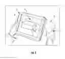
Figure (FIG. 1 illustrates a user adjusting the output of a dimensioning system using an exemplary augmented reality interface. Here, the augmented reality interface 1 is configured with a rear facing camera (i.e., opposite of display facing) for capturing digital images and a display 2 for rendering a real-time video stream of these captured digital images.
The augmented reality interface shown in FIG. 1 is positioned so that the object 3 is displayed on the display 2. In addition, the display 2 shows the object's dimensioning results displayed as wireframe graphics 4. These results are transmitted to the AR interface via a wired or wireless data link. This data link may be a one-way or two-way communication channel between the AR interface and the dimensioning system and may convey information such as augmented reality results and AR interface positioning.
While not shown in FIG. 1, other feedback information, besides wireframe graphics, may be displayed with the images. For example controls, data, and/or tools may displayed in the form of text (e.g., dimensions), images (e.g., range images from a range camera), and/or graphics (e.g., tools). Further, multiple wireframes may be displayed for embodiments where the dimensioning system measures multiple objects simultaneously.
A user may interact with the feedback information (e.g., wireframes) in a variety of ways. A user may move the AR interface (e.g., redirect the AR interface's field of view) to change the perspective view of the object 3 and wireframe 4 accordingly. A user may also reach into the field of view and interact virtually the feedback information.
Virtual interaction may use the recognition of the user's hand, hand-position, and/or gestures in the images captured by the AR interface to affect changes to the dimensioner's output. Virtual interaction may also recognize other cues to affect changes. For example, light from a laser (e.g., laser pointer) may be projected into the field of view to select an object or a portion of the object.
The virtual interaction may affect many possible operations. These operations may include (but are not limited to) selecting an object, selecting an object side, selecting a wireframe, selecting a portion of a wireframe, adjusting the wireframe position, combining wireframes, deleting wireframes, adding/subtracting wireframe elements, and/or resizing wireframes.
A user may also use virtual tools to interact with the results from the dimensioner. Virtual tools are graphics that may be enabled via hand movements in the captured images. Exemplary virtual tools may include (but are not limited to) (i) tools to grab an edge or face of a wireframe (e.g., tweezers), (ii) tools to select an edge/face for subsequent operations (e.g., fine movement), or (iii) tools to grab the entire wireframe for translation/rotation (e.g., an augmented hand).
An exemplary embodiment of an AR image that illustrates a user's interaction with a wireframe using a virtual tool is shown in FIG. 2. Here, the user hand 5 is enabling a virtual tweezer 6 to grab a wireframe 4 surrounding an object 3. The user may adjust the wireframe 4 with the tweezer 6 so that it better fits the object 4.
A user may also use a light beam projected into the field of view to interact with the results from the dimensioner. FIG. 3 depicts an image from an augmented reality interface showing a user interacting with the results of a dimensioning system using a beam of light. Here, a light beam 15 from a laser 16 (e.g., laser pointer) is directed at an object 3 to select the corresponding side 17 of the wireframe 4.
A block diagram of an exemplary dimensioning system 20 enabled for augmented reality interaction is shown in FIG. 4. An object 3 positioned within the dimensioning system's field of view (FOV) 7 can be sensed by the dimensioning system's 3D sensor 8. The 3D sensor is typically an active optical sensor that has a transmitter and receiver. The 3D sensor typically transmits optical radiation (e.g., infrared light) that strikes items in the FOV 7. The optical radiation is reflected from the items and returned to the receiver, where it is gathered and converted into electrical signals.
A processor 9, running software algorithms, may receive/interpret/analyze the electrical signals from the 3D sensor. The algorithms detect changes between the transmitted light and the received light in order to determine the range of the items in the FOV. This range information may be used to determine the dimensions of the items in the FOV.
The processor 9 may be embodied in a variety of ways. Exemplary processors suitable for the present invention include (but are not limited to) microprocessors, application-specific integrated circuits (ASIC), graphics processing units (GPU), digital signal processors (DSP), image processors, and multi-core processors. It is possible that the dimensioning system uses one or more of these processors types to facilitate dimensioning and AR interface operations.
The 3D sensor 8 may use a variety of sensing techniques to gather the information necessary for dimensioning. Some sensing techniques include (but are not limited to) sensing the timing of the transmitted light (e.g., time-of-flight) and sensing the apparent position of the transmitted light (e.g., triangulation, structured light, etc.).
The dimensioning system's augmented reality interface is enabled by a camera 10 and a display 11 that are communicatively coupled to the processor and the 3D sensor. The camera captures digital images of the camera's field of view 12, which corresponds to the 3D sensor's field of view 13. The camera 10 includes the necessary optics and electronics to convert images into electrical signals. Possible cameras for the augmented reality interface include a charge-couple device (CCD) or a complementary metal oxide semiconductor (CMOS) sensor.
The dimensioning system 20 is configured by software (executed by the processor) to recognize adjustment cues in the images. Two exemplary adjustment cues shown in FIG. 3 are a hand 5 and a beam of light 15 projected by a laser 16.
The display 11 presents the dimensioning results and images from the camera to a user. Exemplary displays suitable for the dimensioning system include (but are not limited to) a heads-up display (HUD) and a liquid crystal display (LCD) (e.g., a touch display).
A block diagram of an augmented reality interface 21 enabled is shown in FIG. 5. In this embodiment, the AR interface 21 is not integrated with the dimensioning system 22. Rather, the AR interface is communicatively coupled to the dimensioning system. Typically, communication is accomplished through a wireless data link 23 (e.g., Wi-Fi, Bluetooth, etc.).
An exemplary method correcting dimensioning errors using an augmented reality interface according to an embodiment of the present invention is shown in FIG. 6. A dimensioner returns results 30 that are observed 31 by a user with an augmented reality interface as described previously. The user is able to identify errors visually in the returned results 32 (i.e., errors in the virtual wireframes). If errors are found, then the user may reach into the field of view of the AR interface 33, which may or may not correspond to the field of view of the dimensioner. The user may then select 34 and adjust 35 a virtual wireframe using a hand or a hand-enabled virtual tool. The user then checks whether all errors have been corrected 36. If all errors have been corrected, then the results (e.g., the updated virtual wireframes) may be returned 38, otherwise the user may repeat the aforementioned steps to correct additional errors 37. Once complete, the corrected wireframes are returned 38 (e.g., displayed). In a possible embodiment, the corrected wireframes are returned to the dimensioner for further analysis (e.g., volume calculation, area calculation, etc.).
To supplement the present disclosure, this application incorporates entirely by reference the following commonly assigned patents, patent application publications, and patent applications:
- U.S. Pat. No. 6,832,725; U.S. Pat. No. 7,128,266;
- U.S. Pat. No. 7,159,783; U.S. Pat. No. 7,413,127;
- U.S. Pat. No. 7,726,575; U.S. Pat. No. 8,294,969;
- U.S. Pat. No. 8,317,105; U.S. Pat. No. 8,322,622;
- U.S. Pat. No. 8,366,005; U.S. Pat. No. 8,371,507;
- U.S. Pat. No. 8,376,233; U.S. Pat. No. 8,381,979;
- U.S. Pat. No. 8,390,909; U.S. Pat. No. 8,408,464;
- U.S. Pat. No. 8,408,468; U.S. Pat. No. 8,408,469;
- U.S. Pat. No. 8,424,768; U.S. Pat. No. 8,448,863;
- U.S. Pat. No. 8,457,013; U.S. Pat. No. 8,459,557;
- U.S. Pat. No. 8,469,272; U.S. Pat. No. 8,474,712;
- U.S. Pat. No. 8,479,992; U.S. Pat. No. 8,490,877;
- U.S. Pat. No. 8,517,271; U.S. Pat. No. 8,523,076;
- U.S. Pat. No. 8,528,818; U.S. Pat. No. 8,544,737;
- U.S. Pat. No. 8,548,242; U.S. Pat. No. 8,548,420;
- U.S. Pat. No. 8,550,335; U.S. Pat. No. 8,550,354;
- U.S. Pat. No. 8,550,357; U.S. Pat. No. 8,556,174;
- U.S. Pat. No. 8,556,176; U.S. Pat. No. 8,556,177;
- U.S. Pat. No. 8,559,767; U.S. Pat. No. 8,599,957;
- U.S. Pat. No. 8,561,895; U.S. Pat. No. 8,561,903;
- U.S. Pat. No. 8,561,905; U.S. Pat. No. 8,565,107;
- U.S. Pat. No. 8,571,307; U.S. Pat. No. 8,579,200;
- U.S. Pat. No. 8,583,924; U.S. Pat. No. 8,584,945;
- U.S. Pat. No. 8,587,595; U.S. Pat. No. 8,587,697;
- U.S. Pat. No. 8,588,869; U.S. Pat. No. 8,590,789;
- U.S. Pat. No. 8,596,539; U.S. Pat. No. 8,596,542;
- U.S. Pat. No. 8,596,543; U.S. Pat. No. 8,599,271;
- U.S. Pat. No. 8,599,957; U.S. Pat. No. 8,600,158;
- U.S. Pat. No. 8,600,167; U.S. Pat. No. 8,602,309;
- U.S. Pat. No. 8,608,053; U.S. Pat. No. 8,608,071;
- U.S. Pat. No. 8,611,309; U.S. Pat. No. 8,615,487;
- U.S. Pat. No. 8,616,454; U.S. Pat. No. 8,621,123;
- U.S. Pat. No. 8,622,303; U.S. Pat. No. 8,628,013;
- U.S. Pat. No. 8,628,015; U.S. Pat. No. 8,628,016;
- U.S. Pat. No. 8,629,926; U.S. Pat. No. 8,630,491;
- U.S. Pat. No. 8,635,309; U.S. Pat. No. 8,636,200;
- U.S. Pat. No. 8,636,212; U.S. Pat. No. 8,636,215;
- U.S. Pat. No. 8,636,224; U.S. Pat. No. 8,638,806;
- U.S. Pat. No. 8,640,958; U.S. Pat. No. 8,640,960;
- U.S. Pat. No. 8,643,717; U.S. Pat. No. 8,646,692;
- U.S. Pat. No. 8,646,694; U.S. Pat. No. 8,657,200;
- U.S. Pat. No. 8,659,397; U.S. Pat. No. 8,668,149;
- U.S. Pat. No. 8,678,285; U.S. Pat. No. 8,678,286;
- U.S. Pat. No. 8,682,077; U.S. Pat. No. 8,687,282;
- U.S. Pat. No. 8,692,927; U.S. Pat. No. 8,695,880;
- U.S. Pat. No. 8,698,949; U.S. Pat. No. 8,717,494;
- U.S. Pat. No. 8,717,494; U.S. Pat. No. 8,720,783;
- U.S. Pat. No. 8,723,804; U.S. Pat. No. 8,723,904;
- U.S. Pat. No. 8,727,223; U.S. Pat. No. D702,237;
- U.S. Pat. No. 8,740,082; U.S. Pat. No. 8,740,085;
- U.S. Pat. No. 8,746,563; U.S. Pat. No. 8,750,445;
- U.S. Pat. No. 8,752,766; U.S. Pat. No. 8,756,059;
- U.S. Pat. No. 8,757,495; U.S. Pat. No. 8,760,563;
- U.S. Pat. No. 8,763,909; U.S. Pat. No. 8,777,108;
- U.S. Pat. No. 8,777,109; U.S. Pat. No. 8,779,898;
- U.S. Pat. No. 8,781,520; U.S. Pat. No. 8,783,573;
- U.S. Pat. No. 8,789,757; U.S. Pat. No. 8,789,758;
- U.S. Pat. No. 8,789,759; U.S. Pat. No. 8,794,520;
- U.S. Pat. No. 8,794,522; U.S. Pat. No. 8,794,526;
- U.S. Pat. No. 8,798,367; U.S. Pat. No. 8,807,431;
- U.S. Pat. No. 8,807,432; U.S. Pat. No. 8,820,630;
- International Publication No. 2013/163789;
- International Publication No. 2013/173985;
- International Publication No. 2014/019130;
- International Publication No. 2014/110495;
- U.S. Patent Application Publication No. 2008/0185432;
- U.S. Patent Application Publication No. 2009/0134221;
- U.S. Patent Application Publication No. 2010/0177080;
- U.S. Patent Application Publication No. 2010/0177076;
- U.S. Patent Application Publication No. 2010/0177707;
- U.S. Patent Application Publication No. 2010/0177749;
- U.S. Patent Application Publication No. 2011/0202554;
- U.S. Patent Application Publication No. 2012/0111946;
- U.S. Patent Application Publication No. 2012/0138685;
- U.S. Patent Application Publication No. 2012/0168511;
- U.S. Patent Application Publication No. 2012/0168512;
- U.S. Patent Application Publication No. 2012/0193423;
- U.S. Patent Application Publication No. 2012/0203647;
- U.S. Patent Application Publication No. 2012/0223141;
- U.S. Patent Application Publication No. 2012/0228382;
- U.S. Patent Application Publication No. 2012/0248188;
- U.S. Patent Application Publication No. 2013/0043312;
- U.S. Patent Application Publication No. 2013/0056285;
- U.S. Patent Application Publication No. 2013/0070322;
- U.S. Patent Application Publication No. 2013/0075168;
- U.S. Patent Application Publication No. 2013/0082104;
- U.S. Patent Application Publication No. 2013/0175341;
- U.S. Patent Application Publication No. 2013/0175343;
- U.S. Patent Application Publication No. 2013/0200158;
- U.S. Patent Application Publication No. 2013/0256418;
- U.S. Patent Application Publication No. 2013/0257744;
- U.S. Patent Application Publication No. 2013/0257759;
- U.S. Patent Application Publication No. 2013/0270346;
- U.S. Patent Application Publication No. 2013/0278425;
- U.S. Patent Application Publication No. 2013/0287258;
- U.S. Patent Application Publication No. 2013/0292475;
- U.S. Patent Application Publication No. 2013/0292477;
- U.S. Patent Application Publication No. 2013/0293539;
- U.S. Patent Application Publication No. 2013/0293540;
- U.S. Patent Application Publication No. 2013/0306728;
- U.S. Patent Application Publication No. 2013/0306730;
- U.S. Patent Application Publication No. 2013/0306731;
- U.S. Patent Application Publication No. 2013/0307964;
- U.S. Patent Application Publication No. 2013/0308625;
- U.S. Patent Application Publication No. 2013/0313324;
- U.S. Patent Application Publication No. 2013/0313325;
- U.S. Patent Application Publication No. 2013/0341399;
- U.S. Patent Application Publication No. 2013/0342717;
- U.S. Patent Application Publication No. 2014/0001267;
- U.S. Patent Application Publication No. 2014/0002828;
- U.S. Patent Application Publication No. 2014/0008430;
- U.S. Patent Application Publication No. 2014/0008439;
- U.S. Patent Application Publication No. 2014/0025584;
- U.S. Patent Application Publication No. 2014/0027518;
- U.S. Patent Application Publication No. 2014/0034734;
- U.S. Patent Application Publication No. 2014/0036848;
- U.S. Patent Application Publication No. 2014/0039693;
- U.S. Patent Application Publication No. 2014/0042814;
- U.S. Patent Application Publication No. 2014/0049120;
- U.S. Patent Application Publication No. 2014/0049635;
- U.S. Patent Application Publication No. 2014/0061305;
- U.S. Patent Application Publication No. 2014/0061306;
- U.S. Patent Application Publication No. 2014/0063289;
- U.S. Patent Application Publication No. 2014/0066136;
- U.S. Patent Application Publication No. 2014/0067692;
- U.S. Patent Application Publication No. 2014/0070005;
- U.S. Patent Application Publication No. 2014/0071840;
- U.S. Patent Application Publication No. 2014/0074746;
- U.S. Patent Application Publication No. 2014/0075846;
- U.S. Patent Application Publication No. 2014/0076974;
- U.S. Patent Application Publication No. 2014/0078341;
- U.S. Patent Application Publication No. 2014/0078342;
- U.S. Patent Application Publication No. 2014/0078345;
- U.S. Patent Application Publication No. 2014/0084068;
- U.S. Patent Application Publication No. 2014/0097249;
- U.S. Patent Application Publication No. 2014/0098792;
- U.S. Patent Application Publication No. 2014/0100774;
- U.S. Patent Application Publication No. 2014/0100813;
- U.S. Patent Application Publication No. 2014/0103115;
- U.S. Patent Application Publication No. 2014/0104413;
- U.S. Patent Application Publication No. 2014/0104414;
- U.S. Patent Application Publication No. 2014/0104416;
- U.S. Patent Application Publication No. 2014/0104451;
- U.S. Patent Application Publication No. 2014/0106594;
- U.S. Patent Application Publication No. 2014/0106725;
- U.S. Patent Application Publication No. 2014/0108010;
- U.S. Patent Application Publication No. 2014/0108402;
- U.S. Patent Application Publication No. 2014/0108682;
- U.S. Patent Application Publication No. 2014/0110485;
- U.S. Patent Application Publication No. 2014/0114530;
- U.S. Patent Application Publication No. 2014/0124577;
- U.S. Patent Application Publication No. 2014/0124579;
- U.S. Patent Application Publication No. 2014/0125842;
- U.S. Patent Application Publication No. 2014/0125853;
- U.S. Patent Application Publication No. 2014/0125999;
- U.S. Patent Application Publication No. 2014/0129378;
- U.S. Patent Application Publication No. 2014/0131438;
- U.S. Patent Application Publication No. 2014/0131441;
- U.S. Patent Application Publication No. 2014/0131443;
- U.S. Patent Application Publication No. 2014/0131444;
- U.S. Patent Application Publication No. 2014/0131445;
- U.S. Patent Application Publication No. 2014/0131448;
- U.S. Patent Application Publication No. 2014/0133379;
- U.S. Patent Application Publication No. 2014/0136208;
- U.S. Patent Application Publication No. 2014/0140585;
- U.S. Patent Application Publication No. 2014/0151453;
- U.S. Patent Application Publication No. 2014/0152882;
- U.S. Patent Application Publication No. 2014/0158770;
- U.S. Patent Application Publication No. 2014/0159869;
- U.S. Patent Application Publication No. 2014/0160329;
- U.S. Patent Application Publication No. 2014/0166755;
- U.S. Patent Application Publication No. 2014/0166757;
- U.S. Patent Application Publication No. 2014/0166759;
- U.S. Patent Application Publication No. 2014/0166760;
- U.S. Patent Application Publication No. 2014/0166761;
- U.S. Patent Application Publication No. 2014/0168787;
- U.S. Patent Application Publication No. 2014/0175165;
- U.S. Patent Application Publication No. 2014/0175169;
- U.S. Patent Application Publication No. 2014/0175172;
- U.S. Patent Application Publication No. 2014/0175174;
- U.S. Patent Application Publication No. 2014/0191644;
- U.S. Patent Application Publication No. 2014/0191913;
- U.S. Patent Application Publication No. 2014/0197238;
- U.S. Patent Application Publication No. 2014/0197239;
- U.S. Patent Application Publication No. 2014/0197304;
- U.S. Patent Application Publication No. 2014/0203087;
- U.S. Patent Application Publication No. 2014/0204268;
- U.S. Patent Application Publication No. 2014/0214631;
- U.S. Patent Application Publication No. 2014/0217166;
- U.S. Patent Application Publication No. 2014/0217180;
- U.S. patent application Ser. No. 13/367,978 for a Laser Scanning Module Employing an Elastomeric U-Hinge Based Laser Scanning Assembly, filed Feb. 7, 2012 (Feng et al.);
- U.S. patent application Ser. No. 29/436,337 for an Electronic Device, filed Nov. 5, 2012 (Fitch et al.);
- U.S. patent application Ser. No. 13/771,508 for an Optical Redirection Adapter, filed Feb. 20, 2013 (Anderson);
- U.S. patent application Ser. No. 13/852,097 for a System and Method for Capturing and Preserving Vehicle Event Data, filed Mar. 28, 2013 (Barker et al.);
- U.S. patent application Ser. No. 13/902,110 for a System and Method for Display of Information Using a Vehicle-Mount Computer, filed May 24, 2013 (Hollifield);
- U.S. patent application Ser. No. 13/902,144, for a System and Method for Display of Information Using a Vehicle-Mount Computer, filed May 24, 2013 (Chamberlin);
- U.S. patent application Ser. No. 13/902,242 for a System For Providing A Continuous Communication Link With A Symbol Reading Device, filed May 24, 2013 (Smith et al.);
- U.S. patent application Ser. No. 13/912,262 for a Method of Error Correction for 3D Imaging Device, filed Jun. 7, 2013 (Jovanovski et al.);
- U.S. patent application Ser. No. 13/912,702 for a System and Method for Reading Code Symbols at Long Range Using Source Power Control, filed Jun. 7, 2013 (Xian et al.);
- U.S. patent application Ser. No. 29/458,405 for an Electronic Device, filed Jun. 19, 2013 (Fitch et al.);
- U.S. patent application Ser. No. 13/922,339 for a System and Method for Reading Code Symbols Using a Variable Field of View, filed Jun. 20, 2013 (Xian et al.);
- U.S. patent application Ser. No. 13/927,398 for a Code Symbol Reading System Having Adaptive Autofocus, filed Jun. 26, 2013 (Todeschini);
- U.S. patent application Ser. No. 13/930,913 for a Mobile Device Having an Improved User Interface for Reading Code Symbols, filed Jun. 28, 2013 (Gelay et al.);
- U.S. patent application Ser. No. 29/459,620 for an Electronic Device Enclosure, filed Jul. 2, 2013 (London et al.);
- U.S. patent application Ser. No. 29/459,681 for an Electronic Device Enclosure, filed Jul. 2, 2013 (Chaney et al.);
- U.S. patent application Ser. No. 13/933,415 for an Electronic Device Case, filed Jul. 2, 2013 (London et al.);
- U.S. patent application Ser. No. 29/459,785 for a Scanner and Charging Base, filed Jul. 3, 2013 (Fitch et al.);
- U.S. patent application Ser. No. 29/459,823 for a Scanner, filed Jul. 3, 2013 (Zhou et al.);
- U.S. patent application Ser. No. 13/947,296 for a System and Method for Selectively Reading Code Symbols, filed Jul. 22, 2013 (Rueblinger et al.);
- U.S. patent application Ser. No. 13/950,544 for a Code Symbol Reading System Having Adjustable Object Detection, filed Jul. 25, 2013 (Jiang);
- U.S. patent application Ser. No. 13/961,408 for a Method for Manufacturing Laser Scanners, filed Aug. 7, 2013 (Saber et al.);
- U.S. patent application Ser. No. 14/018,729 for a Method for Operating a Laser Scanner, filed Sep. 5, 2013 (Feng et al.);
- U.S. patent application Ser. No. 14/019,616 for a Device Having Light Source to Reduce Surface Pathogens, filed Sep. 6, 2013 (Todeschini);
- U.S. patent application Ser. No. 14/023,762 for a Handheld Indicia Reader Having Locking Endcap, filed Sep. 11, 2013 (Gannon);
- U.S. patent application Ser. No. 14/035,474 for Augmented-Reality Signature Capture, filed Sep. 24, 2013 (Todeschini);
- U.S. patent application Ser. No. 29/468,118 for an Electronic Device Case, filed Sep. 26, 2013 (Oberpriller et al.);
- U.S. patent application Ser. No. 14/055,234 for Dimensioning System, filed Oct. 16, 2013 (Fletcher);
- U.S. patent application Ser. No. 14/053,314 for Indicia Reader, filed Oct. 14, 2013 (Huck);
- U.S. patent application Ser. No. 14/065,768 for Hybrid System and Method for Reading Indicia, filed Oct. 29, 2013 (Meier et al.);
- U.S. patent application Ser. No. 14/074,746 for Self-Checkout Shopping System, filed Nov. 8, 2013 (Hejl et al.);
- U.S. patent application Ser. No. 14/074,787 for Method and System for Configuring Mobile Devices via NFC Technology, filed Nov. 8, 2013 (Smith et al.);
- U.S. patent application Ser. No. 14/087,190 for Optimal Range Indicators for Bar Code Validation, filed Nov. 22, 2013 (Hejl);
- U.S. patent application Ser. No. 14/094,087 for Method and System for Communicating Information in an Digital Signal, filed Dec. 2, 2013 (Peake et al.);
- U.S. patent application Ser. No. 14/101,965 for High Dynamic-Range Indicia Reading System, filed Dec. 10, 2013 (Xian);
- U.S. patent application Ser. No. 14/150,393 for Indicia-reader Having Unitary Construction Scanner, filed Jan. 8, 2014 (Colavito et al.);
- U.S. patent application Ser. No. 14/154,207 for Laser Barcode Scanner, filed Jan. 14, 2014 (Hou et al.);
- U.S. patent application Ser. No. 14/165,980 for System and Method for Measuring Irregular Objects with a Single Camera filed Jan. 28, 2014 (Li et al.);
- U.S. patent application Ser. No. 14/166,103 for Indicia Reading Terminal Including Optical Filter filed Jan. 28, 2014 (Lu et al.);
- U.S. patent application Ser. No. 14/200,405 for Indicia Reader for Size-Limited Applications filed Mar. 7, 2014 (Feng et al.);
- U.S. patent application Ser. No. 14/231,898 for Hand-Mounted Indicia-Reading Device with Finger Motion Triggering filed Apr. 1, 2014 (Van Horn et al.);
- U.S. patent application Ser. No. 14/250,923 for Reading Apparatus Having Partial Frame Operating Mode filed Apr. 11, 2014, (Deng et al.);
- U.S. patent application Ser. No. 14/257,174 for Imaging Terminal Having Data Compression filed Apr. 21, 2014, (Barber et al.);
- U.S. patent application Ser. No. 14/257,364 for Docking System and Method Using Near Field Communication filed Apr. 21, 2014 (Showering);
- U.S. patent application Ser. No. 14/264,173 for Autofocus Lens System for Indicia Readers filed Apr. 29, 2014 (Ackley et al.);
- U.S. patent application Ser. No. 14/274,858 for Mobile Printer with Optional Battery Accessory filed May 12, 2014 (Marty et al.);
- U.S. patent application Ser. No. 14/277,337 for MULTIPURPOSE OPTICAL READER, filed May 14, 2014 (Jovanovski et al.);
- U.S. patent application Ser. No. 14/283,282 for TERMINAL HAVING ILLUMINATION AND FOCUS CONTROL filed May 21, 2014 (Liu et al.);
- U.S. patent application Ser. No. 14/300,276 for METHOD AND SYSTEM FOR CONSIDERING INFORMATION ABOUT AN EXPECTED RESPONSE WHEN PERFORMING SPEECH RECOGNITION, filed Jun. 10, 2014 (Braho et al.);
- U.S. patent application Ser. No. 14/305,153 for INDICIA READING SYSTEM EMPLOYING DIGITAL GAIN CONTROL filed Jun. 16, 2014 (Xian et al.);
- U.S. patent application Ser. No. 14/310,226 for AUTOFOCUSING OPTICAL IMAGING DEVICE filed Jun. 20, 2014 (Koziol et al.);
- U.S. patent application Ser. No. 14/327,722 for CUSTOMER FACING IMAGING SYSTEMS AND METHODS FOR OBTAINING IMAGES filed Jul. 10, 2014 (Oberpriller et al,);
- U.S. patent application Ser. No. 14/327,827 for a MOBILE-PHONE ADAPTER FOR ELECTRONIC TRANSACTIONS, filed Jul. 10, 2014 (Hejl);
- U.S. patent application Ser. No. 14/329,303 for CELL PHONE READING MODE USING IMAGE TIMER filed Jul. 11, 2014 (Coyle);
- U.S. patent application Ser. No. 14/333,588 for SYMBOL READING SYSTEM WITH INTEGRATED SCALE BASE filed Jul. 17, 2014 (Barten);
- U.S. patent application Ser. No. 14/334,934 for a SYSTEM AND METHOD FOR INDICIA VERIFICATION, filed Jul. 18, 2014 (Hejl);
- U.S. patent application Ser. No. 14/336,188 for METHOD OF AND SYSTEM FOR DETECTING OBJECT WEIGHING INTERFERENCES, Filed Jul. 21, 2014 (Amundsen et al.);
- U.S. patent application Ser. No. 14/339,708 for LASER SCANNING CODE SYMBOL READING SYSTEM, filed Jul. 24, 2014 (Xian et al.);
- U.S. patent application Ser. No. 14/340,627 for an AXIALLY REINFORCED FLEXIBLE SCAN ELEMENT, filed Jul. 25, 2014 (Rueblinger et al.);
- U.S. patent application Ser. No. 14/340,716 for an OPTICAL IMAGER AND METHOD FOR CORRELATING A MEDICATION PACKAGE WITH A PATIENT, filed Jul. 25, 2014 (Ellis);
- U.S. patent application Ser. No. 14/342,544 for Imaging Based Barcode Scanner Engine with Multiple Elements Supported on a Common Printed Circuit Board filed Mar. 4, 2014 (Liu et al.);
- U.S. patent application Ser. No. 14/345,735 for Optical Indicia Reading Terminal with Combined Illumination filed Mar. 19, 2014 (Ouyang);
- U.S. patent application Ser. No. 14/336,188 for METHOD OF AND SYSTEM FOR DETECTING OBJECT WEIGHING INTERFERENCES, Filed Jul. 21, 2014 (Amundsen et al.);
- U.S. patent application Ser. No. 14/355,613 for Optical Indicia Reading Terminal with Color Image Sensor filed May 1, 2014 (Lu et al.);
- U.S. patent application Ser. No. 14/370,237 for WEB-BASED SCAN-TASK ENABLED SYSTEM AND METHOD OF AND APPARATUS FOR DEVELOPING AND DEPLOYING THE SAME ON A CLIENT-SERVER NETWORK filed Jul. 2, 2014 (Chen et al.);
- U.S. patent application Ser. No. 14/370,267 for INDUSTRIAL DESIGN FOR CONSUMER DEVICE BASED SCANNING AND MOBILITY, filed Jul. 2, 2014 (Ma et al.);
- U.S. patent application Ser. No. 14/376,472, for an ENCODED INFORMATION READING TERMINAL INCLUDING HTTP SERVER, filed Aug. 4, 2014 (Lu);
- U.S. patent application Ser. No. 14/379,057 for METHOD OF USING CAMERA SENSOR INTERFACE TO TRANSFER MULTIPLE CHANNELS OF SCAN DATA USING AN IMAGE FORMAT filed Aug. 15, 2014 (Wang et al.);
- U.S. patent application Ser. No. 14/452,697 for INTERACTIVE INDICIA READER, filed Aug. 6, 2014 (Todeschini);
- U.S. patent application Ser. No. 14/453,019 for DIMENSIONING SYSTEM WITH GUIDED ALIGNMENT, filed Aug. 6, 2014 (Li et al.);
- U.S. patent application Ser. No. 14/460,387 for APPARATUS FOR DISPLAYING BAR CODES FROM LIGHT EMITTING DISPLAY SURFACES filed Aug. 15, 2014 (Van Horn et al.);
- U.S. patent application Ser. No. 14/460,829 for ENCODED INFORMATION READING TERMINAL WITH WIRELESS PATH SELECTON CAPABILITY, filed Aug. 15, 2014 (Wang et al.);
- U.S. patent application Ser. No. 14/462,801 for MOBILE COMPUTING DEVICE WITH DATA COGNITION SOFTWARE, filed on Aug. 19, 2014 (Todeschini et al.);
- U.S. patent application Ser. No. 14/446,387 for INDICIA READING TERMINAL PROCESSING PLURALITY OF FRAMES OF IMAGE DATA RESPONSIVELY TO TRIGGER SIGNAL ACTIVATION filed Jul. 30, 2014 (Wang et al.);
- U.S. patent application Ser. No. 14/446,391 for MULTIFUNCTION POINT OF SALE APPARATUS WITH OPTICAL SIGNATURE CAPTURE filed Jul. 30, 2014 (Good et al.);
- U.S. patent application Ser. No. 29/486,759 for an Imaging Terminal, filed Apr. 2, 2014 (Oberpriller et al.);
- U.S. patent application Ser. No. 29/492,903 for an INDICIA SCANNER, filed Jun. 4, 2014 (Zhou et al.); and
- U.S. patent application Ser. No. 29/494,725 for an IN-COUNTER BARCODE SCANNER, filed Jun. 24, 2014 (Oberpriller et al.).
In the specification and/or figures, typical embodiments of the invention have been disclosed. The present invention is not limited to such exemplary embodiments. The use of the term “and/or” includes any and all combinations of one or more of the associated listed items. The figures are schematic representations and so are not necessarily drawn to scale. Unless otherwise noted, specific terms have been used in a generic and descriptive sense and not for purposes of limitation.
Claims
1. A dimensioning system, comprising:
a three-dimensional (3D) sensor for dimensioning objects in a field of view;
a camera for capturing real-time images of the objects in the field of view;
a processor communicatively coupled to the 3D sensor and the camera, the processor configured to create augmented-reality feedback comprising (i) the real-time images captured by the camera and (ii) graphic elements overlaid on the real-time images, wherein the processor is further configured to (i) recognize gestures in the real-time images captured by the camera and (ii) adjust the graphic elements in response to the gestures; and
a display communicatively coupled to the processor for displaying the augmented-reality feedback to a user in real time.
2. The dimensioning system according to claim 1, wherein the gestures comprise a hand gesture.
3. The dimensioning system according to claim 1, wherein the gestures comprise the position and/or motion of a point of light projected into the field of view and reflected from the objects in the field of view.
4. The dimensioning system according to claim 1, wherein the graphic elements comprise wireframes that correspond to edges of the objects in the field of view.
5. The dimensioning system according to claim 4, wherein the graphic elements further comprise virtual tools for adjusting and/or selecting the wireframes.
6. The dimensioning system according to claim 5, wherein the virtual tools comprise (i) a tweezer for grabbing an edge of the wireframes, (ii) a pointer for selecting a face of the wireframes, and/or (iii) a virtual hand for grabbing the wireframes.
7. The dimensioning system according to claim 4, wherein the adjustment of the graphic elements comprises changing the size and/or shape of the wireframes.
8. The dimensioning system according to claim 4, wherein the adjustment of the graphic elements comprises selecting a portion of the wireframes for dimensioning.
9. The dimensioning system according to claim 4, wherein the adjustment of the graphic elements comprises rotating, and/or translating the wireframes.
10. An augmented reality interface for a dimensioning system, comprising:
a camera for capturing images of a field of view that is aligned with the dimensioning system's field of view;
a display for displaying images and graphical information to a user; and
a processor communicatively coupled to the camera, the display, and the dimensioning system, wherein the processor is configured by software to:
(i) receive the images from the camera,
(ii) receive dimensioning information from the dimensioning system, the dimensioning information corresponding to an object in the dimensioning system's field of view,
(iii) create, using the dimensioning information, wireframe graphics that correspond to the edges of the object,
(iv) present the images and the wireframe graphics on the display, the wireframe graphics overlaid and aligned with the object in the images,
(v) recognize adjustment cues in the images, and
(vi) adjust the wireframe graphics in response to the adjustment cues.
11. The augmented reality interface for a dimensioning system according to claim 10, wherein the processor is further configured to:
(i) update the dimensioning information in response to the adjustment to the wireframe graphics, and
(ii) communicate the updated wireframe information to the dimensioning system.
12. The augmented reality interface for a dimensioning system according to claim 10, wherein the adjustment cues comprise a user's hand reaching into the field of view and virtually manipulating the wireframe graphics presented on the display.
13. The augmented reality interface for a dimensioning system according to claim 10, wherein the adjustment cues comprise a light spot projected into the field of view to select a surface indicated by the wireframe graphics presented on the display.
14. The augmented reality interface for a dimensioning system according to claim 10, wherein the adjustment to the wireframe graphics comprises resizing the wireframe graphics.
15. The augmented reality interface for a dimensioning system according to claim 10, wherein the adjustment to the wireframe graphics comprises rotating and/or translating the wireframe graphics.
16. The augmented reality interface for a dimensioning system according to claim 10, wherein the adjustment to the wireframe graphics comprises deleting a portion of the wireframe graphics.
17. The augmented reality interface for a dimensioning system according to claim 10, wherein the adjustment to the wireframe graphics comprises combining wireframe graphics.
18. A method for correcting dimensioning errors using an augmented reality interface, the method comprising:
observing results from a dimensioning system displayed as virtual wireframes overlaid on real-time images of objects in a field of view, the virtual wireframes corresponding to edges of one or more surfaces of one or more objects in the dimensioning system's field of view;
identifying errors in the virtual wireframes;
reaching a hand into the dimensioning system's field of view so that it is displayed with the objects and the virtual wireframes;
selecting one of the virtual wireframes using the hand or a virtual tool enabled by the hand;
adjusting the selected virtual wireframe by moving the hand or the virtual tool; and
repeating the steps identifying, reaching, virtually selecting, and virtually adjusting until all of the errors in the virtual wireframes have been corrected.
19. The method for correcting dimensioning errors using an augmented reality interface according to claim 18, wherein the errors in the virtual wireframes comprise (i) virtual wireframes that overlap, (ii) virtual wireframes that cover more than one object, and/or (iii) virtual wireframes that do not cover an object completely.
20. The method for correcting dimensioning errors using an augmented reality interface according to claim 18, wherein the augmented reality interface is an optical head-mounted display worn by a user.
Images & Drawings included:


Sources:
- United States Patent and Trademark Office - verify current appl. status at the USPTO↗
Similar patent applications:
Recent applications in this class:
- » 20250173001 2025-05-29
MODE SWITCHING FOR INTEGRATED GESTURAL INTERACTION AND MULTI-USER COLLABORATION IN IMMERSIVE VIRTUAL REALITY ENVIRONMENTS - » 20250173000 2025-05-29
SYSTEMS FOR NAVIGATING USER INTERFACES ON MULTIPLE DEVICES BASED ON SPATIAL ORIENTATIONS OF A USER'S HAND, AND METHOD OF USE THEREOF - » 20250172999 2025-05-29
Pinch state detection system and methods - » 20250165080 2025-05-22
Suppression of Hand Gestures upon Detection of Peripheral Events on a Peripheral Device - » 20250165079 2025-05-22
SYSTEMS AND METHODS FOR MACHINE CONTROL - » 20250165078 2025-05-22
INFORMATION PROCESSING APPARATUS AND INFORMATION PROCESSING METHOD - » 20250165077 2025-05-22
WEARABLE DEVICE, GESTURE RECOGNITION METHOD AND NON-TRANSITORY COMPUTER READABLE STORAGE MEDIUM THEREOF - » 20250155988 2025-05-15
Spatiotemporal Smoothing for Improved Hand Tracking - » 20250155987 2025-05-15
BRAIN MACHINE INTERFACE FOR PERFORMING SUSTAINED ACTIONS USING DISCRETE COMMANDS - » 20250155986 2025-05-15
METHOD FOR DETECTING AND DISCRIMINATING GESTURES