LACROSSE STICK HEAD MOUNTING SYSTEM
US20170036080A1
2017-02-09
15/223,354
2016-07-29
✅ Patent granted
US 12,447,384 B2
2025-10-21
-
-
Jeffrey S Vanderveen
STAAS & HALSEY LLP
2036-08-07
Abstract:
A lacrosse stick head has a protrusion at a base of the lacrosse stick head, which internally mounts to the lacrosse stick handle or pole. The protrusion has an angled end, which makes contact with the angled end of the wedged end cap. The protrusion and the wedged end cap are drawn together via a screw through the centerline of the lacrosse stick head and mated to a threaded wedged end cap, creating a wedging force internal to the lacrosse stick handle or pole, and uniting of the lacrosse stick head to the lacrosse stick handle or pole.
Applicant:
Interested in similar patents?
Get notified when new applications in this technology area are published.
Classification:
A63B2102/14 » CPC further
Application of clubs, bats, rackets or the like to the sporting activity ; particular sports involving the use of balls and clubs, bats, rackets, or the like Lacrosse
A63B59/20 » CPC main
Bats, rackets, or the like, not covered by groups - having means, e.g. pockets, netting or adhesive type surfaces, for catching or holding a ball, e.g. for lacrosse or pelota
Description
CROSS-REFERENCE TO RELATED APPLICATIONS
This application is based upon and claims the benefit of priority of U.S. Provisional Application Ser. No. 62/201,159, filed Aug. 5, 2015, the entire contents of which are incorporated herein by reference.
BACKGROUND
1. Field
This invention relates to how a lacrosse stick head is mounted or affixed to a lacrosse stick handle or pole.
2. Description of the Related Art
Most lacrosse stick heads are mounted to the lacrosse stick handle or pole via a single screw which penetrates the lacrosse stick head and lacrosse stick handle or pole where the two pieces overlap.
Thus if the single screw becomes loosened due to vibration or torsion force, the lacrosse stick head will become loosened from the lacrosse stick handle or pole thereby causing the user to have less control over the combined lacrosse stick head and lacrosse stick handle or pole assembly.
SUMMARY
In one aspect, a lacrosse stick head is comprised of a protrusion at the base of the lacrosse stick head, which internally mounts to the lacrosse stick handle or pole, which said protrusion has an angled end, which makes contact with the angled end of the wedged end cap, which are drawn together via a screw through the centerline of the lacrosse stick head and mated to the threaded wedged end cap creating a wedging force internal to the lacrosse stick handle or pole creating the union of the lacrosse stick head to the lacrosse stick handle or pole.
In another aspect, a lacrosse stick head has a first wedge surface of a base and an oblique wedged end cap and a head longitudinal axis. The oblique wedged end cap is disposed proximate to the first wedge surface. The head longitudinal axis is substantially coaxial with a head base longitudinal axis.
In another aspect, a head assembly made up of the lacrosse stick head and the oblique wedged end cap is inserted into a handle. A fastener is passed through a throat of the lacrosse stick head and is substantially coaxial with the head longitudinal axis.
In another aspect, the handle may have a cross-section that is circular, square, triangular, oval, or a polygon.
In another aspect, an angle of the first wedge surface relative to the head longitudinal axis may be oblique, acute, nonzero, positive, 30°, and 45°.
In another aspect, contact between the first wedge surface and the oblique wedged end cap can be repositioned relative to each other to create an offset relative to an axial position of the first wedge surface and the oblique wedged end cap that resists rotation of the lacrosse stick head about the handle longitudinal axis.
In another aspect, contact between the first wedge surface and the oblique wedged end cap can be repositioned relative to each other to create an offset relative to an axial position of the first wedge surface and the oblique wedged end cap that resists longitudinal motion of the lacrosse stick head along the handle longitudinal axis.
In another aspect, the fastener may be a head screw, a bolt, a rivet, a spike, and an anchor.
In another aspect, a lacrosse stick head mounting system has a head having a throat and a basket. The head is fastened to a handle by a fastener. The throat has a planar throat surface at an oblique angle to an axis of rotation of the fastener through the throat. An oblique wedged end cap has a planar handle surface at the oblique angle to the axis of rotation. The planar handle surface contacts the planar throat surface to resist rotation of the head about the axis of rotation.
The above and other features and advantages of the present invention, as well as the structure and operation of various embodiments of the present invention, are described in detail below with reference to the accompanying drawings.
BRIEF DESCRIPTION OF THE DRAWINGS
The accompanying drawings, which are incorporated herein and form part of the specification, illustrate various embodiments of the present invention and, together with the description, further serve to explain the principles of the invention and to enable a person skilled in the pertinent art to make and use the invention. In the drawings, like reference numbers indicate identical or functionally similar elements. A more complete appreciation of the invention and many of the attendant advantages thereof will be readily obtained as the same becomes better understood by reference to the following detailed description when considered in connection with the accompanying drawings, wherein:
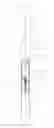
FIG. 1 shows an exploded front view of a lacrosse stick according to an embodiment;
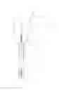
FIG. 2 shows an exploded side view of the lacrosse stick according to an embodiment; and
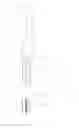
FIG. 3 shows an assembled view of the lacrosse stick according to an embodiment.
DETAILED DESCRIPTION OF THE PREFERRED EMBODIMENTS
In FIGS. 1, 2, and 3 is shown a lacrosse stick head according to an embodiment. FIG. 1 shows a front view of the lacrosse stick head comprised of a protrusion at the base of the lacrosse stick head, which has a wedged end. The wedged end makes contact with a wedged end cap, which are drawn together via a screw through the centerline of the lacrosse stick head and mated to threads in the wedged end cap.
FIG. 2 shows a side view of the lacrosse stick head comprised of a protrusion at the base of the lacrosse stick head, which has a wedged end. The wedged end makes contact with a wedged end cap, which are drawn together via a screw through the centerline of the lacrosse stick head and mated to threads in the wedged end cap.
FIG. 3 shows a side view of the lacrosse stick head mounted to the lacrosse stick handle or pole via the tightening screw. The tightening screw creates wedging force internal to the lacrosse handle or pole therefore securing the lacrosse stick head to the lacrosse stick handle or pole.
The lacrosse stick head has a protruding end 15 at its base, which is to be inserted into the end of the lacrosse handle or pole 16. The protrusion at the base of the lacrosse stick head 11 will have an angled end 13, and a wedge tightening screw tunnel 17 to accommodate the wedge tightening screw 12.
The wedge tightening screw tunnel 17 will be through the centerline of the protruding base 15 of the lacrosse stick head 11. The lacrosse stick head 11 will have a recess 18 to accommodate the head of the wedge tightening screw 12 positioned at the top of the wedge tightening screw tunnel 17 to accommodate the head of the head of the wedge tightening screw 12.
The wedge end cap 14 will fit internal to the lacrosse stick handle or pole 16, will have some internal threads along its centerline to accommodate the wedge tightening screw 12 and have an angle on the end cap 20 to make contact with and supplement or approximately supplement the angle at the end on the protruding base 13 of the lacrosse stick head 11.
The lacrosse stick head 11 and wedge end cap 14 will be mounted to the lacrosse stick handle or pole 16 by inserting the wedge tightening screw 12 into the wedge tightening screw tunnel 17 in the base of the lacrosse stick head 11. The wedge end cap 14 will have its angle on the end cap 20 positioned at a supplemental angle at the end of protruding base of the lacrosse stick head 13. The wedge tightening screw 12 will then mate with the threads for the wedge tightening screw 19 on the wedge end cap 14.
The assembly of the lacrosse stick head 11 connected to the wedge end cap 14 via the wedge tightening screw 12 will be inserted into the end of the lacrosse stick handle or pole 16. By tightening the wedge tightening screw 12 the wedge end cap 14 will be drawn towards the angle at the end of the protruding base 13 of the lacrosse stick head 11. Tightening the wedge tightening screw 12 to the wedge end cap 14 via the threads for the wedge tightening screw 19 will force the wedge end cap 14 to move into the offset position relative to the protruding base of the lacrosse stick head 15.
Increasing the offset between the protruding end if the lacrosse stick head 15 and the wedge end cap 14 will reduce the space between the wedge end cap 14 and the inner wall of the lacrosse stick handle or pole 16 and increasing the offset between the protruding end if the lacrosse stick head 15 and the wedge end cap 14 will reduce the space between the protruding base of the lacrosse stick head 15 and the inner wall of the lacrosse stick handle or pole 16 thereby wedging the lacrosse stick head 11 and wedge end cap 14 inside of the lacrosse stick handle or pole 16 creating the union of the lacrosse stick head 11 to the lacrosse stick handle or pole 16.
In one embodiment, a lacrosse stick head 11 has a first wedge surface 13 of a base 15 and an oblique wedged end cap 20 and a head longitudinal axis 22. The oblique wedged end cap 20 is disposed proximate to the first wedge surface 13. The head longitudinal axis 22 is substantially coaxial with a head base longitudinal axis 24.
A head assembly made up of the lacrosse stick head 11 and the oblique wedged end cap 20 is inserted into a handle 16. A fastener 12 is passed through a throat of the lacrosse stick head 11 and is substantially coaxial with the head longitudinal axis 22.
The handle 16 may have a cross-section that is circular, square, triangular, oval, or a polygon.
An angle of the first wedge surface 13 relative to the head longitudinal axis 22 may be oblique, acute, nonzero, positive, 30°, and 45°.
Contact between the first wedge surface 13 and the oblique wedged end cap 20 can be repositioned relative to each other to create an offset relative to an axial position of the first wedge surface 13 and the oblique wedged end cap 20 that resists rotation of the lacrosse stick head 11 about the handle longitudinal axis 22.
Contact between the first wedge surface 13 and the oblique wedged end cap 20 can be repositioned relative to each other to create an offset relative to an axial position of the first wedge surface 13 and the oblique wedged end cap 20 that resists longitudinal motion of the lacrosse stick head 11 along the handle longitudinal axis 22.
The fastener 12 may be a head screw, a bolt, a rivet, a spike, and an anchor.
In another embodiment, a lacrosse stick head mounting system has a head 11 having a throat 15 and a basket. The head 11 is fastened to a handle by a fastener 12. The throat 15 has a planar throat surface 13 at an oblique angle to an axis of rotation 22 of the fastener 12 through the throat 15. An oblique wedged end cap 14 has a planar handle surface 20 at the oblique angle to the axis of rotation 22. The planar handle surface 20 contacts the planar throat surface 13 to resist rotation of the head 11 about the axis of rotation 22.
In several embodiments, the improved mounting of the lacrosse stick head to the lacrosse stick handle or pole will allow for the lacrosse stick head redesign to be more streamlined due to the lacrosse stick head mount being totally internal to the lacrosse stick handle or pole.
The improved mounting of the lacrosse stick head to the lacrosse stick handle or pole will increase the torsion load, which can be placed on the lacrosse stick head, lacrosse, handle or pole assembly.
The improved mounting of the lacrosse stick head to the lacrosse stick handle or pole will allow for fewer repairs than the old single screw mounting which penetrates the lacrosse stick head and lacrosse stick pole or handle where the two said pieces overlap due to needed to retightening due to screw loosening from vibration or torsion forces.
The improved mounting of the lacrosse stick head to the lacrosse stick handle or pole will contain more gripping force in the mounting contact area between the lacrosse stick mount and the lacrosse stick handle or pole creating a stronger union of the lacrosse stick head to the lacrosse stick handle or pole.
The improved mounting of the lacrosse stick head to the lacrosse stick handle or pole will allow for a stronger union of the lacrosse stick head to the lacrosse handle or pole and increase the torsion load, which can be placed on the lacrosse stick head, lacrosse, handle or pole assembly.
Mounting the wedge tightening screw to be internal to the lacrosse stick head will allow for fewer repairs versus the old external single screw mounting which penetrates from an external position the lacrosse stick head and lacrosse stick handle or pole where the two said pieces overlap and need retightening due to screw loosening from vibration or torsion forces.
The improved mounting of the lacrosse stick head to the lacrosse stick handle or pole will allow for a lacrosse stick head redesign that would allow for a smoother union between the lacrosse stick head and lacrosse stick handle or pole thereby reducing possible injuries.
The improved mounting of the lacrosse stick head to the lacrosse stick handle or pole will reduce lacrosse stick head breakage at the mounting supports due to the mounting will be internal to the lacrosse handle or pole versus the existing mounting being external to the lacrosse stick pole or handle.
Although the description above contains many specificities, these should not be construed as limiting the scope of the invention but as merely providing illustrations of some of the presently preferred embodiments of this invention. For example, the protruding base of the lacrosse stick head and wedge end cap can be of any external shape to accommodate the interior of the lacrosse stick handle or pole, the upper portion of the lacrosse stick head can be of various designs and colors, the lacrosse stick handle or pole can be of various designs, etc.
REFERENCE NUMERALS IN DRAWINGS
-
- 11 lacrosse stick head
- 12 wedge tightening screw
- 13 angle at the end of protruding base
- 14 wedge end cap
- 15 protruding base of lacrosse stick head
- 16 lacrosse stick handle or pole
- 17 wedge tightening screw tunnel
- 18 recess for wedge tightening screw head
- 19 threads for wedge tightening screw
- 20 angle on end cap
The foregoing has described the principles, embodiments, and modes of operation of the present invention. However, the invention should not be construed as being limited to the particular embodiments described above, as they should be regarded as being illustrative and not restrictive. It should be appreciated that variations may be made in those embodiments by those skilled in the art without departing from the scope of the present invention.
While a preferred embodiment of the present invention has been described above, it should be understood that it has been presented by way of example only, and not limitation. Thus, the breadth and scope of the present invention should not be limited by the above described exemplary embodiment.
Obviously, numerous modifications and variations of the present invention are possible in light of the above teachings. It is therefore to be understood that the invention may be practiced otherwise than as specifically described herein.
Claims
What is claimed is:1. A lacrosse stick head comprising:
a first wedge surface of a base and an oblique wedged end cap and a head longitudinal axis, the oblique wedged end cap disposed proximate to the first wedge surface, and the head longitudinal axis substantially coaxial with a head base longitudinal axis; and
a head assembly comprising the lacrosse stick head and the oblique wedged end cap inserted into a handle with a fastener passing through a throat of the lacrosse stick head and substantially coaxial with the head longitudinal axis.
2. The lacrosse stick head of claim 1, wherein a cross-section of the handle is selected from the group consisting of:
circular,
square,
triangular,
oval, and
polygon.
3. The lacrosse stick head of claim 1, wherein an angle of the first wedge surface relative to the head longitudinal axis is selected from the group consisting of:
oblique,
acute,
nonzero,
positive,
30°, and
45°.
4. The lacrosse stick head of claim 1, wherein contact between the first wedge surface and the oblique wedged end cap can be repositioned relative to each other to create an offset relative to an axial position of the first wedge surface and the oblique wedged end cap that resists rotation of the lacrosse stick head about the handle longitudinal axis.
5. The lacrosse stick head of claim 1, wherein contact between the first wedge surface and the oblique wedged end cap can be repositioned relative to each other to create an offset relative to an axial position of the first wedge surface and the oblique wedged end cap that resists longitudinal motion of the lacrosse stick head along the handle longitudinal axis.
6. The lacrosse stick head of claim 1, wherein the fastener is selected from the group consisting of:
a head screw,
a bolt,
a rivet,
a spike, and
an anchor.
7. A lacrosse stick head mounting system, comprising:
a head having a throat and a basket, the head fastened to a handle by a fastener, the throat having a planar throat surface at an oblique angle to an axis of rotation of the fastener through the throat, an oblique wedged end cap comprising a planar handle surface at the oblique angle to the axis of rotation, the planar handle surface contacting the planar throat surface to resist rotation of the head about the axis of rotation.
8. The lacrosse stick head of claim 7, wherein a cross-section of the handle is selected from the group consisting of:
circular,
square,
triangular,
oval, and
polygon.
9. The lacrosse stick head of claim 7, wherein the fastener is selected from the group consisting of:
a head screw,
a bolt,
a rivet,
a spike, and
an anchor.
Images & Drawings included:
Sources:
- United States Patent and Trademark Office - verify current appl. status at the USPTO↗
Recent applications in this class:
- » 20250295966 2025-09-25
Paddle Ball Game Apparatus with Removable Net Assembly - » 20250242217 2025-07-31
DEVICE FOR SECURING LACROSSE MESH WITHOUT KNOTS - » 20250195968 2025-06-19
Method of Using a Game Stick - » 20250153016 2025-05-15
Lacrosse Stick Pocket Enhancement - » 20250099826 2025-03-27
LACROSSE HEAD REMOVAL AND INSTALLATION TOOL - » 20250041684 2025-02-06
SPORTS EQUIPMENT ASSEMBLY - » 20240390751 2024-11-28
PADDED LACROSSE STICK - » 20240252892 2024-08-01
Unitary Lacrosse Stick And Method For Making - » 20240108954 2024-04-04
GRAPHENE ENHANCED LACROSSE SHAFT - » 20240017140 2024-01-18
Lacrosse stick and substrate for pocket