Transportable rowing unit
US20170043208A1
2017-02-16
14/821,838
2015-08-10
✅ Patent granted
US 9,764,185 B2
2017-09-19
-
-
Andrew S Lo
Steven W. Webb
2035-08-10
Abstract:
The unit includes a single rowing and seat component connected to a simplified braking mechanism. The sliding seat is attached to a dual track frame. The rowing component includes a handle attached to a deep profile sprocket and synchronous belt attached to a flywheel. The unit folds onto itself, and telescopes together compacting and weighing approximately 27 pounds for transport in a small carry case.
Applicant:
Interested in similar patents?
Get notified when new applications in this technology area are published.
Classification:
A63B23/0233 » CPC further
Exercising apparatus specially adapted for particular parts of the body for the abdomen, the spinal column or the torso muscles related to shoulders (e.g. chest muscles) Muscles of the back, e.g. by an extension of the body against a resistance, reverse crunch
A63B22/0076 » CPC main
Exercising apparatus specially adapted for conditioning the cardio-vascular system, for training agility or co-ordination of movements Rowing machines for conditioning the cardio-vascular system
A63B22/0087 » CPC further
Exercising apparatus specially adapted for conditioning the cardio-vascular system, for training agility or co-ordination of movements with a seat or torso support moving during the exercise, e.g. reformers
A63B21/0088 » CPC further
Exercising apparatus for developing or strengthening the muscles or joints of the body by working against a counterforce, with or without measuring devices using hydraulic or pneumatic force-resisters using pneumatic force-resisters by moving the surrounding air
A63B21/225 » CPC further
Exercising apparatus for developing or strengthening the muscles or joints of the body by working against a counterforce, with or without measuring devices; Resisting devices with rotary bodies with flywheels
A63B2022/0079 » CPC further
Exercising apparatus specially adapted for conditioning the cardio-vascular system, for training agility or co-ordination of movements; Rowing machines for conditioning the cardio-vascular system with a pulling cable
A63B2022/0082 » CPC further
Exercising apparatus specially adapted for conditioning the cardio-vascular system, for training agility or co-ordination of movements; Rowing machines for conditioning the cardio-vascular system with pivoting handlebars
A63B2210/00 » CPC further
Space saving
A63B2210/50 » CPC further
Space saving Size reducing arrangements for stowing or transport
F16B7/105 » CPC further
Connections of rods or tubes, e.g. of non-circular section, mutually, including resilient connections; Telescoping systems locking in discrete positions, e.g. in extreme extended position
A63B21/00 IPC
Exercising apparatus for developing or strengthening the muscles or joints of the body by working against a counterforce, with or without measuring devices
A63B22/00 IPC
Exercising apparatus specially adapted for conditioning the cardio-vascular system, for training agility or co-ordination of movements
A63B21/008 IPC
Exercising apparatus for developing or strengthening the muscles or joints of the body by working against a counterforce, with or without measuring devices using hydraulic or pneumatic force-resisters
A63B21/22 IPC
Exercising apparatus for developing or strengthening the muscles or joints of the body by working against a counterforce, with or without measuring devices Resisting devices with rotary bodies
F16B7/10 IPC
Connections of rods or tubes, e.g. of non-circular section, mutually, including resilient connections Telescoping systems
Description
BACKGROUND OF THE INVENTION
Field Of The Invention
This invention pertains to exercise devices and exercise rowing units, particularly to units that are light weight, that fold and telescope in such a manner as to become compact in size. It also pertains to units which provide a feel which is similar to the actual sensation of rowing.
Description of the Related Art
In the prior art it is typical to have a friction brake to provide the resistance for training. These units are inherently inferior and wear out quickly. There have been improvements to the above described devices such as shown, for instance, in U.S. Pat. No. 3,315,959, issued Apr. 25, 1967 to G. Carnielli, for A Hinge and Braking Device for Stationary Rowing Exercising Apparatuses. Other devices which can be used as examples of current state-of-the-art devices are in the patent issued to A. R. Johnson on Aug. 16, 1966, U.S. Pat. No. 3,266,801 for a Fluid-Operated Rowing Machine and in the patent issued to P. Elia et. al., U.S. Pat. No. 3,380,737 on Apr. 30, 1968, for Rowing-Type Exercising Equipment plus in the patent issued to Dreissigacker et. al., U.S. Pat No. 4,396,188 issued Aug. 2, 1983 for a Stationary Rowing Unit.
As shown in these patents, the devices provide a sensation of rowing. The machine themselves are built around a large footprint with weight that requires two people to transport the unit. Storage of these units is also another factor.
BRIEF SUMMARY OF THE INVENTION
It is a particular object of this invention to set forth a unit that is easy to store, transportable, and weight of approximately 27 pounds. A unit that that folds and telescopes together on itself and is carried in a small carry case. Further, a unit with a belt and sprocket coupled with rotating flywheel providing resistance. Said flywheel is connected to the main shaft assembly which is attached to the frame, Also a sliding seat, and adjustable foot positioning element. A braking means for said flywheel, handle means interposed between said rowing means, driving flywheel and return means for said drive are integrated to the device.
Further objects and features of this invention will become more apparent by reference to the following description.
BRIEF DESCRIPTION OF THE SEVERAL VIEWS OF THE DRAWINGS
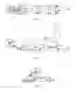
FIG. 1 is a top plan view of the transportable rowing unit.
FIG. 2 is a side elevation view thereof; and
FIG. 3 is a side elevation view of rowing unit in transportable position.
DETAILED DESCRIPTION OF THE INVENTION
As shown in the figures, the invention is a transportable rowing unit 10, comprised of a wind resistant flywheel 11, a gearing mechanism 12 connected rotatably with said wind resistant flywheel 11, said flywheel 11 and gearing mechanism 12 is held in place by fold frame assembly 13, comprised of a locking nut mechanism 14 and the fold frame assembly 13,
said fold frame assembly 13 connected rotatably to a foot stretcher 15, with attached strap 16, attached to main frame square tube 17,
cross member 18 is attached to tube 17, said tube 17 possessing fixedly attached seat rails 19,20,
said tube 17 enclosing slideably telescoping square tube 21, which telescoping square tube 21 slideably encloses smaller telescoping square tube 22, which telescoping and smaller telescoping square tubes 21,22 are released by cam pins 23 and 24, respectively. This arrangement allows sections of the invention to slide into one another for compact transport.
To use the invention, rower grasps handle 25, attached to synchronous belt 26, and pulls on said handle 25, which by pulling, drives gearing mechanism 12, and flywheel 11; elastic system 27 returns handle 25 to static position. Seat car 28, moves rower fore and aft along seat rails 19,20.
While I have described my invention in connection with a specific embodiment of function and portability thereof it is to be clearly understood that this is done only by way of example. It is not as a limitation to the scope of my invention as set forth in the objects thereof and the appended claim.
Claims
I claim:1. A transportable rowing unit, said rowing unit comprised of a horizontally extended frame, a foldable frame assembly, a pulling handle and pull cable, and a seat car,
the horizontally extended frame comprised of a main frame comprised of square cross section metal tubing with a nested square tube located slideably within the horizontally extended frame, the nested square tube possessing a smaller-diameter nested square tube within it,
the nested square tube and the smaller-diameter nested square tube prevented from sliding within each other and said horizontally extended frame and held in place by means of two cam pins,
the horizontally extended frame connected at one end to a foldable frame assembly, said assembly comprised of a foldeable frame, said foldable frame foldable around a lock nut, the foldable frame possessing at its end a wind-resistant flywheel and a gearing mechanism, the gearing mechanism connected via pull cable around the axis of the wind-resistant flywheel to the pull handle,
the other end of the pull cable passing through said horizontally extended frame and the nested and smaller-diameter nested square tubes to an elastic system positioned at the end of the smaller-diameter nested square tube,
said seat car mounted slideably on two sliding rails which are attached fixedly to the horizontally extended frame.
2. The transportable rowing unit of claim 1 where the horizontally extended frame, the nested and smaller-diameter nested square tubes are comprised of tube steel.
3. A method of use for the transportable rowing unit of claim 1 to prepare it for transport, comprised of the steps of
collapsing the smaller-diameter nested square tub into the nested square tube after releasing the cam pins,
collapsing the nested square tube into the horizontally extended frame,
folding the foldable frame towards the rest of the rowing unit around the lock nut after releasing the lock nut,
tightening the lock nut.
Images & Drawings included:

Sources:
- United States Patent and Trademark Office - verify current appl. status at the USPTO↗
Similar patent applications:
Recent applications in this class:
- » 20250281791 2025-09-11
Rowing Exercise Machines Having A Configurable Rowing Feel - » 20250229123 2025-07-17
Dry Land Trainer - » 20250213912 2025-07-03
EXERCISE MACHINE WITH MOVABLE BELT OR CHAIN - » 20250152996 2025-05-15
TRANSLATING CARRIAGE EXERCISE MACHINES AND METHODS OF USE - » 20250041658 2025-02-06
PORTABLE EXERCISE APPARATUS - » 20250025744 2025-01-23
Rower Accessory System for Exercise Machine - » 20250018243 2025-01-16
ROW BAR MOUNTING ASSEMBLY - » 20250010128 2025-01-09
MULTI-FUNCTIONAL EXERCISE MACHINE - » 20240408442 2024-12-12
Rowing Machine Adaptor - » 20240408441 2024-12-12
TWO-WAY ROW MACHINE