Integrated input/output connector
US20170052921A1
2017-02-23
14/831,169
2015-08-20
✅ Patent granted
US 10,198,391 B2
2019-02-05
-
-
Zachary K Huson
Locke Lord LLP | Joshua L. Jones | Georgi Korobanov
2036-10-05
Abstract:
An active input/output connector includes a first printed circuit board and a second printed circuit board enclosed within a housing. A first plug is in electronic communication with the first printed circuit board. A second plug is in electronic communication with the second printed circuit board. The first and second printed circuit boards are connected for communication of sensor signals from the first plug to the second plug.
Inventors:
- Kenneth J. Trotman 18 🇺🇸 Granby, CT, United States
- Jason C. Duffy 5 🇺🇸 Granby, CT, United States
Assignee:
- HAMILTON SUNDSTRAND CORPORATION 2,631 🇺🇸 Charlotte, NC, United States
- Hamilton Sunstrand Corporation 267 🇺🇸 Charlotte, NC, United States
Applicant:
Interested in similar patents?
Get notified when new applications in this technology area are published.
Classification:
G06F13/4081 » CPC main
Interconnection of, or transfer of information or other signals between, memories, input/output devices or central processing units; Information transfer, e.g. on bus; Bus structure; Device-to-bus coupling; Electrical coupling Live connection to bus, e.g. hot-plugging
H01R13/6675 » CPC further
Details of coupling devices of the kinds covered by groups or -; Structural association with built-in electrical component with built-in electronic circuit with built-in power supply
G06F13/40 IPC
Interconnection of, or transfer of information or other signals between, memories, input/output devices or central processing units; Information transfer, e.g. on bus Bus structure
H01R13/66 IPC
Details of coupling devices of the kinds covered by groups or - Structural association with built-in electrical component
H01R13/5202 » CPC further
Details of coupling devices of the kinds covered by groups or -; Bases; Cases; Dustproof, splashproof, drip-proof, waterproof, or flameproof cases Sealing means between parts of housing or between housing part and a wall, e.g. sealing rings
H01R2201/26 » CPC further
Connectors or connections adapted for particular applications for vehicles
H01R13/52 IPC
Details of coupling devices of the kinds covered by groups or -; Bases; Cases Dustproof, splashproof, drip-proof, waterproof, or flameproof cases
H01R13/6658 » CPC further
Details of coupling devices of the kinds covered by groups or -; Structural association with built-in electrical component with built-in electronic circuit on printed circuit board
H01R31/065 » CPC further
Coupling parts supported only by co-operation with counterpart; Intermediate parts for linking two coupling parts, e.g. adapter with built-in electric apparatus
H01R13/622 » CPC further
Details of coupling devices of the kinds covered by groups or -; Means for facilitating engagement or disengagement of coupling parts or for holding them in engagement Screw-ring or screw-casing
H01R13/00 IPC
Details of coupling devices of the kinds covered by groups or -
H01R12/73 » CPC further
Structural associations of a plurality of mutually-insulated electrical connecting elements, specially adapted for printed circuits, e.g. printed circuit boards [PCBs], flat or ribbon cables, or like generally planar structures, e.g. terminal strips, terminal blocks; Coupling devices specially adapted for printed circuits, flat or ribbon cables, or like generally planar structures; Terminals specially adapted for contact with, or insertion into, printed circuits, flat or ribbon cables, or like generally planar structures; Coupling devices for rigid printing circuits or like structures coupling with the edge of the rigid printed circuits or like structures connecting to other rigid printed circuits or like structures
H01R31/06 IPC
Coupling parts supported only by co-operation with counterpart Intermediate parts for linking two coupling parts, e.g. adapter
H03M1/00 » CPC further
Analogue/digital conversion; Digital/analogue conversion
Description
GOVERNMENT RIGHTS STATEMENT
This invention was made with government support under contract number FA8650-09-D-2923 awarded by the United States Air Force. The government has certain rights in the invention.
BACKGROUND OF THE INVENTION
1. Field of the Invention
This present disclosure relates to electronic systems and, more particularly, to apparatuses for providing input/output connectors capable of use with a plurality of physical connector arrangements.
2. Description of Related Art
Many modern vehicle applications utilize electronic sensors and controllers in their standard operations. In a typical vehicle, many of the components will require data from sensors or other components to perform their designated function. To facilitate the data transfer between components, most vehicles use a bundle of wires and interconnects, referred to as an electrical harness. The harness can contain thousands of data lines, typically constructed of copper wires, and can be heavy. In such a construction each data line has an interconnect on each end. The interconnects can be plugged into the vehicle components, and data can then be communicated through the harness to a component connected at the opposite end of the data line.
Current state of the art electrical harnesses utilize analog data transmission, requiring dedicated wires in the harness for each component. Analog signals are used because most sensors and other components require analog data or take analog measurements.
In order to reduce the weight of the harness, attempts have been made to utilize digital communications between the components. These attempts have typically been met with failure at least in part because many of the sensors and other components in existing systems have not been modified to allow for digital communications.
Thus, there is a need in the art for improved devices for input/output connections. The present disclosure provides a solution for this need.
SUMMARY OF THE INVENTION
A active input/output connector includes a first printed circuit board and a second printed circuit board enclosed within a housing. A first plug is in electronic communication with the first printed circuit board. A second plug is in electronic communication with the second printed circuit board. The first and second printed circuit boards are connected for communication of sensor signals from the first plug to the second plug.
A collar can be threadably engaged to the housing with a watertight sealant around a threaded interface of the collar. The collar can engage the housing to create a watertight seal around components within the housing. The collar can include a plurality of anti-rotation legs. Each of the first and second printed circuit boards can include a plurality of indentations for slidably accepting a respective anti-rotation leg therein. The anti-rotation legs positioned between the second plug and the housing prevent rotation of the second plug. The collar can include an O-ring positioned between the second plug and the housing to provide an environmental seal with the second plug.
The first circuit board can include a power supply and processor. The second circuit board can be an analog circuit board. The first printed circuit board can be configured to convert sensor signals to standard digital format for a central computer. The first circuit board can include at least one board to board connectors and the second circuit board includes at least one opening for accepting a respective board to board connector therein. It is also contemplated that, the first and second circuit boards will be mated together.
The first plug can be configured and adapted to connect directly to aircraft avionics sensors and to receive an interconnect harness.
These and other features of the systems and methods of the subject disclosure will become more readily apparent to those skilled in the art from the following detailed description of the preferred embodiments taken in conjunction with the drawings.
BRIEF DESCRIPTION OF THE DRAWINGS
So that those skilled in the art to which the subject disclosure appertains will readily understand how to make and use the devices and methods of the subject disclosure without undue experimentation, preferred embodiments thereof will be described in detail herein below with reference to certain figures, wherein:
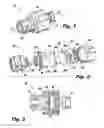
FIG. 1 is a perspective view of an exemplary embodiment of active input/output connector constructed in accordance with the present disclosure;
FIG. 2 is an exploded perspective view of the connector of FIG. 1, showing components of the connector configured to communicate sensor signals; and
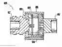
FIG. 3 is a cross-sectional side elevation view of the assembled connector of FIG. 1 taken along line 3-3.
DETAILED DESCRIPTION OF THE PREFERRED EMBODIMENTS
Reference will now be made to the drawings wherein like reference numerals identify similar structural features or aspects of the subject disclosure. For purposes of explanation and illustration, and not limitation, a partial view of an exemplary embodiment of an input/output (TO) connector in accordance with the disclosure is shown in FIG. 1 and is designated generally by reference character 100. Other embodiments of the connector in accordance with the disclosure, or aspects thereof, are provided in FIGS. 2-3, as will be described.
FIG. 1 illustrates the IO connector 100 of the present disclosure. The connector 100 includes a housing 106 for storing components of the connector 100 between a first plug 112 and a second plug 114. With reference to FIG. 2 an exploded view of the IO connector 100 is shown. The connector 100 is configured and adapted to interface with various sensors, for example sensors onboard an aircraft. The connector 100 allows for interfacing with the existing sensors on the aircraft without additional cost to the sensor or the central processing computer and allows for reduction in wiring harness weight. The connector 100 includes a first printed circuit board 102 and a second printed circuit board 104 enclosed within the housing 106. The first printed circuit board 102 includes a power supply, processor and communication means. The second printed circuit 104 is an analog board. The first printed circuit board 104 includes at least two board-to-board connections 108 extending outwardly towards the second printed circuit board 104. The second printed circuit boards include at least one opening 108a for accepting a respective board-to-board connector therein. In addition to or in lieu of board-to-board connections 108, the first and second printed circuit boards 102,104 can be mated together.
The first plug 112 is in electrical communication through leads 112a with the first printed circuit board 102 and the second plug 114 is similarly in electrical communication 114a with the second printed circuit board 104. The first and second plugs 112, 114 can be standard connections, for example the first plug can be a shell size 13 plug and the second plug can be a shell size 13 receptacle. The first and second printed circuit boards 102, 104 are connected to communicate sensor signals between the first and second plugs 112, 114. For example, the first printed circuit board 102 is configured to convert sensor signals received from the second circuit board 104 to a standard digital format to transmit sensor data through the first plug 112. It is envisioned that current systems can be retrofitted with the active connector 100 of the present disclosure. For example, referring to the state of the art in aircraft, the current aircraft harness systems can be disconnected from the sensors and the connector can be attached to the sensor. A new harness using lighter and less wiring can be added to the connector to communicate the digital signals outputted from the connector without having to replace the existing sensors or central avionics.
With reference to FIGS. 2 and 3, a collar 120 is positioned between the first printed circuit board 102 and the first plug 112 and threadably engages the housing. The collar has a watertight sealant around a threaded surface 122 which engages threads 124 of the housing 106 to create a watertight seal around the components within the housing 106. The collar 120 further provides an anti-rotation feature to the connector. The collar includes a plurality of anti-rotation legs 120a. Each of the first and second printed circuit boards 102, 104 includes a plurality of indentations 102a, 104a, respectively, along respective outer edges for slideably accepting a respective anti-rotation leg 120a therein. An O-ring 130 is also included within connector 100 to further provide an environmental seal. The O-ring 130 is disposed between the second plug 114 and the housing 106 to provide an environmental seal with the second plug 114.
The systems of the present disclosure, as described above and shown in the drawings, provide for an active IO connector with superior properties including digital to analog conversion while being accessible for current and future systems. While the apparatus and methods of the subject disclosure have been shown and described with reference to preferred embodiments, those skilled in the art will readily appreciate that change and/or modification may be made thereto without departing from the scope of the subject disclosure.
Claims
What is claimed is:1. An active input/output connector, comprising:
a first printed circuit board and a second printed circuit board enclosed within a housing;
a first plug in electronic communication with the first printed circuit board; and
a second plug in electronic communication with the second printed circuit board,
wherein the first and second printed circuit boards are connected for communication of sensor signals from the first plug to the second plug.
2. The connector of claim 1, further comprising a collar threadably engaged to the housing having a watertight sealant around a threaded interface of the collar which engages the housing to create a watertight seal around components within the housing.
3. The connector of claim 2, wherein the collar includes a plurality of anti-rotation legs for engaging the first and second printed circuit boards.
4. The connector of claim 3, wherein each of the first and second printed circuit boards includes a plurality of indentations for slidably accepting a respective anti-rotation leg therein.
5. The connector of claim 1, further comprising an O-ring positioned between the second plug and the housing to provide an environmental seal with the second plug.
6. The connector of claim 1, wherein the first circuit board includes a power supply and processor.
7. The connector of claim 6, wherein the second circuit board is an analog circuit board.
8. The connector of claim 7, wherein the first printed circuit board is configured to convert sensor signals to standard digital format for a central computer.
9. The connector of claim 7, wherein the first circuit board includes at least two board to board connectors and the second circuit board includes at least one opening for accepting a respective board to board connector therein.
10. The connector of claim 7, wherein the first and second circuit boards are mated together.
11. The connector as in any of the preceding claims, wherein the first plug is configured and adapted to connect directly to aircraft avionics sensors and the second plug is configured and adapted to receive a wiring harness.
12. An active input/output connector, comprising:
a housing;
a collar threadably engaging the housing configured to prevent rotation and seal components within the housing;
a first printed circuit board and a second printed circuit board enclosed within the housing;
a first plug threaded to the collar in electronic communication with the first printed circuit board; and
a second plug enclosed within the housing in electronic communication with the second printed circuit board,
wherein the first and second printed circuit boards are connected for communication of sensor signals from the first plug to the second plug.
Images & Drawings included:
Sources:
- United States Patent and Trademark Office - verify current appl. status at the USPTO↗
Recent applications in this class:
- » 20250265213 2025-08-21
PCIE DEVICE MANAGEMENT METHOD, DEVICE, AND SERVER - » 20250173299 2025-05-29
HOT-SWAPPABLE STRUCTURE OF CONNECTOR AND METHOD THEREOF - » 20250117351 2025-04-10
SERVER SYSTEM, AND METHOD FOR IMPLEMENTING HOT- SWAPPING ON A SERVER - » 20240427723 2024-12-26
STORAGE DEVICES CONNECTORS - » 20240394208 2024-11-28
EXPANSION CARD ADAPTATION - » 20240370398 2024-11-07
UNIVERSAL INTERSYSTEM CONNECTION FOR A WEARABLE DISPLAY DEVICE - » 20240370397 2024-11-07
SYSTEM AND METHOD FOR DYNAMICALLY FREEZING INFORMATION HANDLING SYSTEM PORTS TO MINIMIZE POWER CONSUMED BY IDLE PLUG AND PLAY DEVICES - » 20240345981 2024-10-17
DUAL CONNECTION PERIPHERAL DEVICE WITH CAPTIVE CABLE AND AUXILIARY PORT - » 20240311326 2024-09-19
Controlling Driver Access Based on Docking Status - » 20240303212 2024-09-12
INDUSTRIAL ELECTRICAL CONNECTOR HAVING A DATA DIODE MODULE
Recent applications for this Assignee:
- » 20250260037 2025-08-14
SYSTEMS AND METHODS FOR ALANE-BASED POWER GENERATION - » 20250250000 2025-08-07
HYDRAULIC DRAG BRAKE - » 20250230772 2025-07-17
MULTI TEMPERATURE GENERATOR AND ENGINE SHARED OIL - » 20250227854 2025-07-10
COVERLAY AS PRINTED CIRCUIT BOARD (PCB) VOLTAGE INSULATOR UNDER CONNECTORS - » 20250226734 2025-07-10
COMPOSITE ROTORS AND METHODS OF MAKING COMPOSITE ROTORS - » 20250224141 2025-07-10
THERMOELECTRIC VORTEX TUBES - » 20250218620 2025-07-03
ISOLATION BARRIER SYSTEMS - » 20250217200 2025-07-03
DECENTRALIZED SCHEDULER OF COMPUTATION JOBS FOR UNSTABLE NETWORK OF HETEROGENOUS NODES - » 20250196039 2025-06-19
FILTER ASSEMBLY - » 20250189500 2025-06-12
AEROSOL DETECTION SYSTEMS