Electronic device having latching portions
US20170055357A1
2017-02-23
15/238,887
2016-08-17
✅ Patent granted
US 9,979,803 B2
2018-05-22
-
-
Hung S Bui
Wei Te Chung | Ming Chieh Chang
2036-08-17
Abstract:
An electronic device includes: a framework; a number of modules assembled detachably to the framework; and a number of latching portions assembling the modules on the framework. Each latching portion includes a ball spring beam having a first positioning portion and a first contacting beam, a reinforcement beam having a second positioning portion attached to the first positioning portion and a second contacting beam spaced from the first contacting beam, and a screw affixing the first positioning portion and the second positioning portion to the framework. The first contacting beam has a tuber mated with the module.
Assignee:
- FOXCONN INTERCONNECT TECHNOLOGY LIMITED 922 Grand Cayman, Cayman Islands
Applicant:
Interested in similar patents?
Get notified when new applications in this technology area are published.
Classification:
H05K7/1401 » CPC main
Constructional details common to different types of electric apparatus; Mounting supporting structure in casing or on frame or rack comprising clamping or extracting means
H05K7/1401 » CPC main
Constructional details common to different types of electric apparatus; Mounting supporting structure in casing or on frame or rack comprising clamping or extracting means
H05K5/0256 » CPC further
Casings, cabinets or drawers for electric apparatus; Details of interchangeable modules or receptacles therefor, e.g. cartridge mechanisms
H05K5/0256 » CPC further
Casings, cabinets or drawers for electric apparatus; Details of interchangeable modules or receptacles therefor, e.g. cartridge mechanisms
H05K7/14 IPC
Constructional details common to different types of electric apparatus Mounting supporting structure in casing or on frame or rack
H05K7/14 IPC
Constructional details common to different types of electric apparatus Mounting supporting structure in casing or on frame or rack
H05K7/12 » CPC further
Constructional details common to different types of electric apparatus; Arrangements of circuit components or wiring on supporting structure Resilient or clamping means for holding component to structure
H05K7/12 » CPC further
Constructional details common to different types of electric apparatus; Arrangements of circuit components or wiring on supporting structure Resilient or clamping means for holding component to structure
H05K5/02 IPC
Casings, cabinets or drawers for electric apparatus Details
H05K5/02 IPC
Casings, cabinets or drawers for electric apparatus Details
H04M1/0202 » CPC main
Substation equipment, e.g. for use by subscribers; Constructional features of telephone sets Portable telephone sets, e.g. cordless phones, mobile phones or bar type handsets
H05K5/00 IPC
Casings, cabinets or drawers for electric apparatus
H05K5/00 IPC
Casings, cabinets or drawers for electric apparatus
H04M1/02 IPC
Substation equipment, e.g. for use by subscribers Constructional features of telephone sets
G06F1/16 » CPC further
Details not covered by groups - and Constructional details or arrangements
Description
BACKGROUND OF THE INVENTION
1. Field of the Invention
The present disclosure relates generally to an electronic device, and more particularly to an electronic device with a number of latching portions.
2. Description of Related Arts
U.S. Patent Application Publication No. 20150288422 discloses a system for enabling a chassis-coupled modular mobile electronic device. The system includes a modular electronic device enablement system, a set of module couplers, and a framework or chassis. The module couplers preferably couple modules mechanically to the chassis. The module couplers may have detents or structures that resist movement of the modules when they are fully coupled, including spring-loaded balls mounted on a surface of the module that fits into corresponding shallow holes on a complementary surface of the module coupler. The module coupler may also retain the module using a latching mechanism, e.g., a pin that when extended prevents the module from being removed, or a snap latch that holds the module tight against the contact surfaces of the module coupler when engaged. The module couplers preferably have mechanical guides or other guides to aid in aligning the module during coupling and in module retention through friction.
An electronic device having improved latching portions is desired.
SUMMARY OF THE INVENTION
Accordingly, an object of the present invention is to provide an electronic device having a number of latching portions for grouping a plurality of modules on a chassis or framework.
To achieve the above object, an electronic device comprises: a framework; a plurality of modules assembled detachably to the framework; and a plurality of latching portions assembling the modules on the framework, each latching portion comprising a ball spring beam comprising a first positioning portion and a first contacting beam, a reinforcement beam having a second positioning portion attached to the first positioning portion and a second contacting beam spaced from the first contacting beam, and a screw affixing the first positioning portion and the second positioning portion to the framework, the first contacting beam having a tuber mated with the module.
Other objects, advantages and novel features of the invention will become more apparent from the following detailed description when taken in conjunction with the accompanying drawings.
BRIEF DESCRIPTION OF THE DRAWINGS
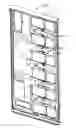
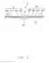
FIG. 1 is a perspective, assembled view of an electronic device in a first embodiment;
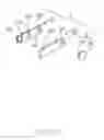
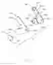
FIG. 2 is a perspective, exploded view of a latching portion of the electronic device in the first embodiment;
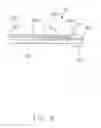
FIG. 3 is an elevation view of the latching portion of the electronic device in the first embodiment;
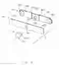
FIG. 4 is a perspective, exploded view of the latching portion of the electronic device in a second embodiment;
FIG. 5 is an elevation view of the latching portion of the electronic device in the second embodiment;
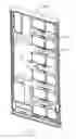
FIG. 6 is a perspective, assembled view of the electronic device in the second embodiment;
FIG. 7 is a perspective, exploded view of the latching portion of the electronic device in a third embodiment;
FIG. 8 is an left view of the latching portion of the electronic device in the third embodiment; and
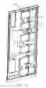
FIG. 9 is a back view of two modules attached to the electronic device.
DETAILED DESCRIPTION OF THE PREFERRED EMBODIMENT
Reference will now be made in detail to the preferred embodiment of the present invention.
Referring to FIGS. 1 to 9, an electronic device 100 includes a framework 1, a number of latching portions 3, 3′, 3″ and a number of modules 101 detachably attached to the framework 1 via the latching portions 3, 3′, 3″. The framework 1 extends in a horizontal direction and defines a longitudinal direction, a transverse direction perpendicular to the longitudinal direction, and a vertical direction perpendicular to the transverse direction and the longitudinal direction. The modules 101 are attached to/detached from the framework 1 along the vertical direction.
Referring to FIGS. 2-5 and 7-8 in a first through third embodiments, each latching portion 3, 3′, 3″ includes a screw or attaching pin 31, 31′, 31″ a ball spring beam 32, 32′, 32″, and a reinforcement beam 33, 33′, 33″. The screw 31, 31′, 31″ is used for fastening the ball spring beam 32, 32′, 32″ and the reinforcement beam 33, 33′, 33″ to the framework 1. The screw 31, 31′, 31″ includes a base portion 311, 311′, 311″ and a post portion 312, 312′, 312″ extending upwardly from the base portion 311, 311′, 311″ along the vertical direction. The diameter of the base portion 311, 311′, 311″ is longer than the diameter of the post portion 312, 312′, 312″. The reinforcement beam 33, 33′, 33″ is fastened to the screw 31, 31′, 31″ to ball spring beam 32, 32′, 32″.
The ball spring beam 32, 32′, 32″ includes a first positioning portion 321, 321′, 321″ a first contacting beam 322, 322′, 322″ in a different plane with the first positioning portion 321, 321′, 321″ and a stepped portion 323, 323′, 323″ connected the first positioning portion 321, 321′, 321″ and the first contacting beam 322, 322′, 322″. The first positioning portion 321, 321′, 321″ defines a first opening 320, 320′, 320″ and the post portion 312, 312′, 312″ is inserted through the first opening 320, 320′, 320″. The first contacting beam 322, 322′, 322″ includes a number of tubers 324, 324′, 324″ latching with the modules. The tubers 324, 324′, 324″ are formed at one surface of the ball spring beam 32, 32′, 32″ separated from the reinforcement beam 33, 33′, 33″.
The reinforcement beam 33, 33′, 33″ includes a second positioning portion 331, 331′, 331″ and a second contacting beam 332, 332′, 332″ coplanar with the second positioning portion 331, 331′, 331″. The second positioning portion 331, 331′, 331″ defines a second opening for insertion of the post portion 312, 312′, 312″. When the screw 31, 31′, 31″ is inserted though the first opening 320, 320′, 320″ and the second opening 330, 330′, 330″, the first positioning portion 321, 321′, 321″ and the second positioning portion 331, 331′, 331″ are connected with each other by spot welding for preventing the relative rotation between the ball spring beam 32, 32′, 32″ and the reinforcement beam 33, 33′, 33″. The first contacting beam 322, 322′, 322″ is separated from the second contacting beam 332, 332′, 332″ along the vertical direction.
Referring to FIGS. 2 to 3, the latching portions 3 in the first embodiment are shown. The second positioning portion 331 and the second contacting beam 332 are located at two sides of the reinforcement portion 33. The first positioning portion 321 is located at one side of the stepped portion 323 corresponding to the second positioning portion. The first contacting beam 322 is located at the other side of the stepped portion 323. The first opening 320 is located at one side of the first positioning portion 321. The second opening 330 is located at one side of the second positioning portion 331 corresponding to the first opening 320. The screw 31 is inserted through the first opening 320 and the second opening 330 to connect the ball spring beam 32 and the reinforcement portion 33.
Referring to FIGS. 4 to 5, the latching portions 3′ in the second embodiment are shown. The second positioning portion 331′ is located at a middle of the reinforcement portion 33′. The second opening 330′ is located at a middle of the second positioning portion 331′. The second contacting beam 332′ is divided into two parts located at two sides of the second positioning portion 331′. The first positioning portion 321′ is located at a middle of the ball spring beam 32′ corresponding to the second positioning portion 331′. The first opening 320′ is located at a middle of the first positioning portion 321′. The first contacting beam 322′ is divided into two parts located at two sides of the first positioning portion 321′ and connected with the stepped portion 323′. The screw 31′ is inserted through the first opening 320′ and the second opening 330′ to connect the ball spring beam 32′ and the reinforcement portion 33′.
Referring to FIGS. 7 to 8, the latching portions 3″ in the third embodiment are shown. The first contacting beam 322″ is divided into two parts extending from the first positioning portion 321″. The two parts of the first contacting beam 322″ have therebetween a first angle between 0 and 180 degree. The second contacting beam 332″ is divided into two parts extending from the second positioning portion 331″. The two parts of the second contacting beam 332″ have therebetween a second angle equal to the first angle.
The ball spring beam 32, 32′, 32″ and the reinforcement beam 33, 33′, 33″ are made of two different materials. The thickness of the ball spring beam 32, 32′, 32″ is smaller than the thickness of the reinforcement beam 33, 33′, 33″. The ball spring beam 32, 32′, 32″ is greater than the reinforcement beam 33, 33′, 33″ in ductility and the ball spring beam 32, 32′, 32″ is weaker than the reinforcement beam 33, 33′, 33″ in strength. When the modules 101 are assembled to framework 1, the modules 101 are resisted against by the tubers 324 of the latching portions 3. The first contacting beam 322, 322′, 322″ is susceptible to rotate caused by compression for the ductility of the ball spring beam 32, 32′, 32″. The reinforcement beam 33, 33′, 33″ could support the ball spring beam 32, 32′, 32″ for the strength of the reinforcement beam 33, 33′, 33″. The first contacting beam 322, 322′, 322″ is deflected downwardly into contacting with the second contacting beam 332, 332′, 332″. The ball spring beam 32, 32′, 32″ continues to press downwardly against the reinforcement beam 33, 33′, 33″ to reduce the amount of compression avoiding permanent deformation of the reinforcement beam 33, 33′, 33″.
When the modules 101 of the electronic device 100 need to be replaced, the modules 101 are detached from the framework 1, the retention force between the framework 1 and the modules 101 needs to be overcome.
While a preferred embodiment in accordance with the present invention has been shown and described, equivalent modifications and changes known to persons skilled in the art according to the spirit of the present invention are considered within the scope of the present invention as described in the appended claims.
Claims
What is claimed is:1. An electronic device comprising:
a framework;
a plurality of modules assembled detachably to the framework; and
a plurality of latching portions assembling the modules on the framework, each latching portion comprising a ball spring beam comprising a first positioning portion and a first contacting beam, a reinforcement beam having a second positioning portion attached to the first positioning portion and a second contacting beam spaced from the first contacting beam, and a screw affixing the first positioning portion and the second positioning portion to the framework, the first contacting beam having a tuber mated with the module.
2. The electronic device as claimed in claim 1, wherein the ball spring beam comprises a stepped portion connected with the first positioning portion and the first contacting beam, and the first positioning portion and the first contacting beam extend in respective planes.
3. The electronic device as claimed in claim 2, wherein the second positioning portion and the second contacting beam are stacked.
4. The electronic device as claimed in claim 1, wherein the screw comprises a base portion and a post portion, the first positioning portion defines a first opening, the second positioning portion defines a second opening, and the post portion is inserted through the first opening and the second opening.
5. The electronic device as claimed in claim 4, wherein the first positioning portion and the second positioning portion are attached together by spot welding.
6. The electronic device as claimed in claim 1, wherein the ball spring beam and the reinforcement beam are made from different materials, and the ball spring beam is more ductile than the reinforcement beam.
7. The electronic device as claimed in claim 6, wherein the ball spring beam is thicker than the reinforcement beam.
8. The electronic device as claimed in claim 1, wherein the second contacting beam includes two parts located alignedly at two sides of the second positioning portion, and the first contacting beam includes two parts located alignedly at two sides of the first positioning portion.
9. The electronic device as claimed in claim 1, wherein the first contacting beam includes two parts extending angularly from the first positioning portion, and the second contacting beam includes two parts extending angularly from the second positioning portion.
10. An electronic device comprising:
a framework defining two opposite first and second surfaces in a vertical direction with a plurality of through holes extending therethrough in said vertical direction;
a plurality of modules detachably attached upon the first surface; and
a plurality of latching portions positioned upon the second surface to assemble the modules on the framework, each latching portion comprising a ball spring beam and a reinforcement beam, said spring beam being sandwiched between the reinforcement beam and the framework, said ball spring beam comprising a first positioning portion and a first contacting beam, said reinforcement beam having a second positioning portion and a second contacting beam, said second positioning portion attached to the first positioning portion and further fixed to the framework, said second contacting beam being spaced from the first contacting beam in said vertical direction; wherein
the first contacting beam includes a tuber extending through the corresponding through hole for coupling to the corresponding module, and said ball spring beam is deflectable in the vertical direction.
11. The electronic device as claimed in claim 10, wherein the spring beam and the reinforcement beam have different thicknesses and different materials from each other.
12. The electronic device as claimed in claim 10, wherein both the second positioning portion and the first positioning portion are attached to the framework by an attaching pin.
13. The electronic device as claimed in claim 10, wherein said reinforcement beam is immoveable.
14. The electronic device as claimed in claim 10, wherein said first positioning portion is offset from the first contacting beam in the vertical direction.
15. The electronic device as claimed in claim 14, wherein said second positioning portion is coplanar with said second contacting beam.
Images & Drawings included:

Sources:
- United States Patent and Trademark Office - verify current appl. status at the USPTO↗
Recent applications in this class:
- » 20250254813 2025-08-07
EJECTOR - » 20250185200 2025-06-05
UNIVERSAL MOUNTING BRACKET - » 20250159831 2025-05-15
UNIVERSAL MOUNTING BRACKET - » 20250133676 2025-04-24
LOCKING MECHANISM FOR LIQUID COOLED PLUGGABLE MODULES - » 20250016946 2025-01-09
PUSH-PULL ROTATING MECHANISM AND LATCH DEVICE HAVING THE SAME - » 20250016945 2025-01-09
BUCKLING DEVICE AND CHASSIS - » 20240431060 2024-12-26
Universal mounting bracket - » 20240215192 2024-06-27
ELECTRONIC DEVICE EJECTION MECHANISM WITH SELECTIVELY DISABLEABLE EJECTION FUNCTION - » 20240206099 2024-06-20
SELF-RETRACTABLE EJECTOR ASSEMBLY FOR AUGMENTED FIELD REPLACEABLE UNIT (FRU) EXTRACTION - » 20240008209 2024-01-04
Portable streaming media player holder
Recent applications for this Assignee:
- » 20240199157 2024-06-20
METHOD OF CONTROLLING STATE OF ELECTRIC ASSIST BICYCLE, CONTROL SYSTEM, AND ELECTRONIC DEVICE - » 20240177887 2024-05-30
CORE WIRE AND METHOD OF MAKING SAME AND CABLE INCLUDING THE CORE WIRE - » 20240072477 2024-02-29
ELECTRICAL CONNECTOR WITH IMPROVED CONTACTS - » 20240055792 2024-02-15
Electrical connector having an angled part and a U-shaped plate together defining a tubular structure - » 20230352880 2023-11-02
ELECTRICAL CONNECTOR WITH IMPROVED INSERTING MEMBER - » 20230335934 2023-10-19
ELECTRICAL CONNECTOR - » 20230307870 2023-09-28
Electrical connector assembly having improved locking elements - » 20230283018 2023-09-07
ELECTRICAL CONNECTOR ASSEMBLY WITH IMPROVED TERMINALS - » 20230268679 2023-08-24
Electrical connector assembly - » 20230238732 2023-07-27
ELECTRICAL CONNECTOR ASSEMBLY HAVING A METAL PLATE FOR MOUNTING A CONNECTOR TO A HOUSING