Parallel motion heat energy power machine and working method thereof
US20170058701A1
2017-03-02
15/307,839
2014-09-23
✅ Patent granted
US 9,708,935 B2
2017-07-18
WO; PCT/CN2014/087197; 20140923
WO; WO2015/165200; 20151105
Jason Shanske
Gokalp Bayramoglu
2034-09-23
Abstract:
A parallel motion heat energy power machine and a working method thereof, includes a heat collector, an insulating pipe, a gasification reactor, an atomizer, a cylinder, a piston, a piston ring, an automatic exhaust valve, a cooler, a liquid storage tank, a pressure pump, a push-pull rod, an insulating layer, and a housing. The two cylinders are oppositely arranged on the housing in parallel. The piston is arranged inside the cylinder. The piston is provided with the piston ring. The pistons are arranged on both ends of the push-pull rod. The heat collector is connected to the gasification reactor through the insulating pipe. The atomizer is arranged on the air inlet end of the gasification reactor. The parallel motion heat energy power machine and working method thereof has a high heat-energy conversion efficiency. It is energy-saving, environmentally friendly, and less noisy.
Assignee:
- Yuanjun Guo 3 🇨🇳 Yongzhou, China
Applicant:
Interested in similar patents?
Get notified when new applications in this technology area are published.
Classification:
F01B31/28 » CPC further
Component parts, details, or accessories not provided for in, or of interest apart from, other groups; Other component parts, details, or accessories, peculiar to steam engines Cylinders or cylinder covers
F01K13/00 IPC
General layout or general methods of operation of complete plants
F01K13/006 » CPC further
General layout or general methods of operation of complete plants Auxiliaries or details not otherwise provided for
F01K23/064 » CPC further
Plants characterised by more than one engine delivering power external to the plant, the engines being driven by different fluids the engine cycles being thermally coupled combustion heat from one cycle heating the fluid in another cycle in combination with an industrial process, e.g. chemical, metallurgical
F01K23/065 » CPC further
Plants characterised by more than one engine delivering power external to the plant, the engines being driven by different fluids the engine cycles being thermally coupled combustion heat from one cycle heating the fluid in another cycle the combustion taking place in an internal combustion piston engine, e.g. a diesel engine
F03G6/003 » CPC further
Devices for producing mechanical power from solar energy having a Rankine cycle
F01K23/06 IPC
Plants characterised by more than one engine delivering power external to the plant, the engines being driven by different fluids the engine cycles being thermally coupled combustion heat from one cycle heating the fluid in another cycle
F03G6/00 IPC
Devices for producing mechanical power from solar energy
F03G7/04 » CPC further
Mechanical-power-producing mechanisms, not otherwise provided for or using energy sources not otherwise provided for using pressure differences or thermal differences occurring in nature
F01B11/004 » CPC further
Reciprocating-piston machines or engines without rotary main shaft, e.g. of free-piston type in which the movement in the two directions is obtained by two single acting piston motors, each acting in one direction
F02B63/041 » CPC further
Adaptations of engines for driving pumps, hand-held tools or electric generators; Portable combinations of engines with engine-driven devices for electric generators Linear electric generators
F01B23/10 » CPC further
Adaptations of machines or engines for special use; Combinations of engines with devices driven thereby Adaptations for driving, or combinations with, electric generators
F03G7/00 IPC
Mechanical-power-producing mechanisms, not otherwise provided for or using energy sources not otherwise provided for
F02G1/044 » CPC further
Hot gas positive-displacement engine plants of closed-cycle type the engine being operated by expansion and contraction of a mass of working gas which is heated and cooled in one of a plurality of constantly communicating expansible chambers, e.g. Stirling cycle type engines having at least two working members, e.g. pistons, delivering power output
F01B11/00 IPC
Reciprocating-piston machines or engines without rotary main shaft, e.g. of free-piston type
F01K3/18 » CPC further
Plants characterised by the use of steam or heat accumulators, or intermediate steam heaters, therein having heaters
F01K3/02 » CPC main
Plants characterised by the use of steam or heat accumulators, or intermediate steam heaters, therein Use of accumulators and specific engine types; Control thereof
F02B63/04 IPC
Adaptations of engines for driving pumps, hand-held tools or electric generators; Portable combinations of engines with engine-driven devices for electric generators
F02B71/04 » CPC further
Free-piston engines; Engines without rotary main shaft Adaptations of such engines for special use; Combinations of such engines with apparatus driven thereby
F01B29/12 » CPC further
Machines or engines with pertinent characteristics other than those provided for in preceding main groups; Reciprocating-piston machines or engines not otherwise provided for; Engines Steam engines
F01B31/08 » CPC further
Component parts, details, or accessories not provided for in, or of interest apart from, other groups Cooling of steam engines ; Heating; Heat insulation
Description
CROSS REFERENCE TO RELATED APPLICATIONS
This application is the national phase entry of International Application No. PCT/CN2014/087197, filed on Sep. 23, 2014, which is based upon and claims priority to CN 201410177409.0, filed on Apr. 30, 2014, the entire contents of which are incorporated herein by reference.
TECHNICAL FIELD
The invention relates to the field of thermal energy power equipment, especially the power machine which can convert heat energy from the solar energy, the geothermal, the high-temperature gas generated by burning of combustibles, the thermal energy or the exhaust gas of internal combustion engine, and the high-temperature gas discharged from factory into the kinetic energy.
BACKGROUND
Conventional power equipment includes the steam engines, internal combustion engines, and external combustion engines.
Steam engine: It cannot work without the boiler. The whole machine is heavy and large. The pressure and the temperature of the new steam cannot be too high, and the exhaust pressure cannot be too low. The heat efficiency is hard to improve. It is a reciprocating machine. The inertia restrains the improvement of the rotational speed. The working is not continuous. The flow of steam is restrained, which limits the improvement of the power.
Internal combustion engine: It has a complicated structure, a high requirement of fuel, and strict requirement of the cleanliness of fuel. It pollutes the environment.
External combustion engine: For example, Stirling engine is one kind of external combustion engine. Compared with internal combustion engine, Stirling engine ha s the following advantages:
It is suitable for all kinds of energy, not matter what state the energy is derived from, liquid, gas, or solid fuel. When using the heat-carrying system (e.g., heat pipe) to heat indirectly, almost all high-temperature heat source (e.g., solar radioactive isotope and nuclear reaction) can be used, while the engine itself (except the heater) does not need any change. At the same time, Stirling engine does not need a compressing machine to increase the pressure, which can be met by an ordinary fan. The fuel with relatively high impurity content is allowed. The unit capacity of Stirling engine is small, the capacity of which ranges from 20 to 50 kw. The system capacity can be increased or reduced according to local conditions. The structure is simple. The number of parts of the external combustion engine is 40% less than that of an internal combustion engine. It has a significant margin of price discount and a low maintenance cost.
When Stirling engine is running, the fuel is burning continuously in the combustion chamber which is outside the cylinder. The working medium, which is independent from the gas, absorbs the heat from the heater and works to the outside environment according to the Stirling cycle. Thus, the engine knocking and intermittent combustion of the internal combustion engine and the like are avoided. An efficient, less noisy, and low-exhaust operation is realized. As being efficient, the total energy efficiency reaches more than 80%. As being less noisy, the noise at a place which is one meter from the bare machine is lower than 68 dBA. As being low-exhaust, the emission of tail gas meets the standard of Euro 5.
Since the working medium does not burn, the external combustion engine avoids the problem of knocking of the conventional internal combustion engine, such that high efficiency, low-noise, low-polluting, and low-running-costs are realized. The external combustion engine can burn various gases, such as natural gas, biogas, petroleum gas, hydrogen, gas, etc. Liquid fuels like diesel, liquefied petroleum gas, etc. can also be used. Burning woods, the solar energy, etc. can also be used. As long as the temperature of the hot chamber reaches 700° C., the equipment will run and work. Lower the environmental temperature, the higher will be the efficiency of the power generation. The most remarkable advantage of the external combustion engine is that the output and efficiency are not affected by the altitude, which makes it very suitable for using in high-altitude areas.
Meanwhile, the mainly existing problems and defects of Stirling engine are as follows: the manufacturing cost is high; the working medium sealing technology is difficult the reliability and serving life of the sealing part have problems; the material cost is high; the power adjusting control system is complex; the machine is heavy; the costs of the expansion chamber, the compression chamber, the heater, the cooling chamber, the regenerator, etc. are high; and the heat loss is twice to three times than that of an internal combustion engine.
Organic Rankine Cycle system includes a pump, an evaporator, an expander, a generator, a condenser, etc. The heat collector absorbs the solar radiation. The temperature of the heat exchanging medium inside the heat collector increases. The heat is transmitted to the organic working medium from the heat exchanging medium through the evaporator. The organic working medium is heated in the evaporator under a constant pressure. The gaseous organic working medium with a high pressure enters the expander to work through expanding, so as to drive the generator to generate power. The organic working medium discharged from the tail of the expander enters the condenser to condense under a constant pressure. After increasing the pressure by the pump, the organic working medium output from the condenser enters the evaporator, such that one power generation cycle is completed.
Organic Rankine Cycle system has the following defects. The conversion efficiency is low. The size is huge. The expander which has a complex structure is essential to work.
SUMMARY OF THE INVENTION
The invention overcomes the existing problems that the costs of the expansion chamber, the compression chamber, the heater, the cooling chamber, the regenerator, etc. are high; and the heat loss is twice to three times than that of an internal combustion engine. The invention overcomes the technical problem that Organic Rankine Cycle system needs an expander or a steam turbine, which renders a high manufacturing cost. The invention provides a parallel motion heat energy power machine that is a heat power machine which combines the advantages of Stirling engine and Organic Rankine Cycle system. After heat is absorbed by the heat collector, the gasification reactor is heated, to make the working medium gasify and expand under a high temperature to push the piston to generate the kinetic energy to work.
The invention provides a heat energy power machine which has a high heat conversion efficiency, in which the working medium is recycled, the output power within the maximum power range is adjustable by adjusting the amount of the working medium, the output power is adjustable by adjusting the temperature, and the machine output power is stable.
The technical solution of the invention is: a parallel motion heat energy power machine, characterized in that, comprising a heat collector, an insulating pipe, a gasification reactor, an atomizer, a cylinder, a piston, a piston ring, an automatic exhaust valve, a cooler, a liquid storage tank, a pressure pump, a push-pull rod, an insulating layer, and a housing. The two cylinders are oppositely arranged on the housing in parallel. The piston is arranged inside the cylinder. The piston is provided with the piston ring. The pistons are arranged on both ends of the push-pull rod. The heat collector is connected to the gasification reactor through the insulating pipe. The atomizer is arranged on the air inlet end of the gasification reactor. The atomizer is connected to the pressure pump through the pipe. The pressure pump is connected to the liquid storage tank through the pipe. The gasification reactor is arranged on the top dead center of the cylinder. The automatic exhaust valve is arranged on the bottom dead center of the cylinder. The automatic exhaust valve is connected to the cooler through the pipe. The cooler is connected to the liquid storage tank through the pipe. The outer layer of the housing is provided with the insulating layer.
Furthermore, the heat collector absorbs the solar energy, the geothermal energy, the high-temperature gas generated by burning the combustible, the exhaust gas of an internal combustion engine, the high-temperature gas discharged from a factory, or other heat energy.
Furthermore, the gasification reactor includes a pressure vessel, a gasification conducting strip, a gas hole, and an atomizer. The gasification conducting strips are arranged on the pressure vessels. The gas holes are arrayed on the gasification conducting strip. The atomizer is arranged on the air inlet end of the pressure vessel.
Furthermore, the pressure pump is connected to the push-pull rod. The pressure pump opens and closes once whenever the circulation is completed.
Furthermore, the push-pull rod is provided with a transmission shaft, which connects to the rotor of a generator to cut magnetic induction lines to form a parallel motion heat energy power machine power generation apparatus.
A work method of the above parallel motion heat energy power machine is: the heat collector absorbs the solar energy, the geothermal energy, the high-temperature gas generated by burning a combustible, the heat energy or exhaust gas of an internal combustion engine, the high-temperature gas discharged from a factory, or other heat energy. The heat is transmitted to the gasification reactor directly or via the pipe. The pipe is provided with flowing heat conducting medium. The liquid working medium is injected through the pressure pumps into the gasification reactor to be atomized. The atomized working medium is gasified and expanded by the gasification reactor. When the piston reaches the bottom dead center of the cylinder, the working gas is discharged from the automatic exhaust valve. The discharged gaseous working medium is cooled down by the cooler. Meanwhile, the other piston reaches the top dead center of the cylinder. The pressure pump of the cylinder opens, such that the liquid working medium is injected through the atomizers into the gasification reactor to be gasified and expanded to push the piston to work. The pressure pumps open and close in turns. The pistons inside two cylinders take turns to work. The kinetic energy is output by the push-pull rod.
The advantages of the invention is: 1. the working medium can be repeatedly used without pollution; 2. the heat energy conversion efficiency is 65%-98%; 3. the output power can be adjusted by adjusting the capacity and number of the machine cylinder according to desired power; 4, the output power can be adjusted within the maximum power range by adjusting the injecting liquid; 5. the machine works by gasifying the working medium, which does not generate knocking during the whole process; 6. the machine has a simple structure, low manufacturing cost, and uses the automatic exhaust function to reduce energy loss; 7. the working power of the present invention is twice than that of the single cylinder; 8. conventional energy consumption can be replaced, which is economic, energy-saving, environment friendly, and less noisy.
BRIEF DESCRIPTION OF THE DRAWINGS
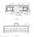
FIG. 1 is the structural schematic diagram of the invention;
FIG. 2 is the structural diagram of the gasification reactor of the invention;
In figures: 1 is a heat collector; 2 is an insulating pipe; 3 is a gasification reactor; 4 is an atomizer; 5 is a cylinder; 6 is a piston; 7 is a piston ring; 8 is an automatic exhaust valve; 9 is a cooler; 10 is a liquid storage tank; 11 is a pressure pump; 12 is a push-pull rod; 13 is an insulating layer; 14 is a housing; 15 is a pressure vessel; 16 is it gasification conducting strip; 17 is a gas hole.
DETAILED DESCRIPTION OF THE EMBODIMENT
Referring to FIGS. 1-2, the embodiments of the invention are as follows:
Embodiment 1
A parallel motion heat energy power machine includes a heat collector 1, insulating pipes 2. gasification reactors 3, atomizers 4, cylinders 5, pistons 6, piston rings 7, automatic exhaust valves 8, cooler 9, liquid storage tank 10, pressure pumps 11, push-pull rod 12, insulating layer 13, and a housing 14. Two cylinders 5 are oppositely arranged on housing 14 in parallel Piston 6 is arranged inside cylinders 5. Piston 6 is provided with piston rings 7. Pistons 6 are arranged on both ends of push-pull rod 12. Heat collector 1 is connected to gasification reactor 3 through insulating pipe 2. Atomizer 4 is arranged on the air inlet end of gasification reactors 3. Atomizer 4 is connected to pressure pumps 11 through the pipes. Pressure pump 11 is connected to liquid storage tank 10 through the pipes. Gasification reactor 3 is arranged on the top dead center of cylinder 5. Automatic exhaust valve 8 is arranged on the bottom dead center of cylinder 5. Automatic exhaust valve 8 is connected to cooler 9 through the pipes. Cooler 9 is connected to liquid storage tank 10 through the pipes. The outer layer of the housing 14 is provided with insulating layer 13.
Embodiment 2
The parallel motion heat energy power machine as described in Embodiment 1, the gasification reactor includes pressure vessel 15, gasification conducting strip 16, gas hole 17, atomizer 4. Gasification conducting strip 16 is arranged on pressure vessel 15. Gas hole 17 is arrayed on gasification conducting strip 16. Atomizer 4 is arranged on the air inlet end of pressure vessel 15. Pressure pump 11 is associated with push-pull rod 12. pressure pump 11 opens and closes once whenever the circulation is completed. Push-pull rod 12 is provided with a transmission shaft, which connects to the rotator of the generator to cut the magnetic induction lines. Cooler 9 uses the natural water cooling method or the condenser.
Claims
What is claimed is:1. A parallel motion heat energy power machine, comprising a heat collector, an insulating pipe, a gasification reactor, an atomizer, a cylinder, a piston, a piston ring, an automatic exhaust valve, a cooler, a liquid storage tank, a pressure pump, a push-pull rod (12), an insulating layer, and a housing;
wherein two cylinders are oppositely arranged on the housing parallel;
wherein the piston is arranged inside the cylinder;
wherein the pistol is provided with the piston ring;
wherein the piston is arranged on both ends of the push-pull rod;
wherein the heat collector is connected to the gasification reactor through the insulating pipe;
wherein the atomizer is arranged on an air inlet end of the gasification reactor;
wherein the atomizer is connected to the pressure pump through the pipe;
wherein the pressure pump is connected to the liquid storage tank through the pipe;
wherein the gasification reactor is arranged on a top dead center of the cylinder;
wherein the automatic exhaust valve is arranged on a bottom dead center of the cylinder;
wherein the automatic exhaust valve is connected to the cooler through the pipes;
wherein the cooler is connected to the liquid storage tank through the pipe; and
wherein the outer layer of the housing is provided with the insulating layer.
2. The parallel motion heat energy power machine according to claim 1, wherein the heat collector can absorb solar energy, geothermal energy, high-temperature gas generated by burning of a combustible, exhaust gas of an internal combustion engine, high-temperature gas discharged from a factory.
3. The parallel motion heat energy power machine according to claim 1, wherein the gasification reactor includes a pressure vessel, a gasification conducting strip, a plurality of gas hole, and an atomizer;
wherein the gasification conducting strip is arranged on the pressure vessel;
wherein a plurality of gas holes are arrayed on the gasification conducting strip; and
wherein the atomizer is arranged on an air inlet end of the pressure vessel.
4. The parallel motion heat energy power machine according to claim 1, wherein the pressure pump is connected to the push-pull rod; wherein the pressure pump opens and closes once whenever a circulation is completed.
5. The parallel motion heat energy power machine power generation device according to claim 1, wherein the push-pull rod is provided with a transmission shaft, which connects to a rotor of a generator to cut magnetic induction lines.
6. A working method of the parallel motion heat energy power machine according to claim 1, comprising:
absorbing, by the hot collector, solar energy, geothermal energy, high-temperature gas generated by burning a combustible, heat energy or exhaust gas of an internal combustion engine, high-temperature gas discharged from a factory, or other heat energy;
transmitting the heat to a gasification reactor directly or via a pipe, wherein the pipe is provided with flowing heat conducting medium;
injecting, through the pressure pump, liquid working medium into the gasification reactor to be atomized;
gasifying and expanding, by the gasification reactor, the atomized working medium;
discharging working gas from the automatic exhaust valve when the piston reaches a bottom dead center of the cylinder;
cooling the discharged gaseous working medium by the cooler;
meanwhile, when the other piston reaches a top dead center of the cylinder, the pressure pump of the cylinder opens, the liquid working medium is injected into the gasification reactor through the atomizer so as to gasify and expand to push the piston to work;
wherein a plurality of pressure pumps open and close in turns;
wherein the pistons inside two cylinders take turns to work; and
wherein kinetic energy is output by the push-pull rod.
7. The working method of the parallel motion heat energy power machine according to claim 2, comprising:
absorbing, by the heat collector, solar energy, geothermal energy, high-temperature gas generated by burning a combustible, heat energy or exhaust gas of an internal combustion engine, high-temperature gas discharged from a factory, or other heat energy:
transmitting the heat to a gasification reactor directly or via a pipe, wherein the pipe is provided with flowing heat conducting medium;
injecting, through the pressure pinup liquid working medium into the gasification reactor to be atomized;
gasifying and expanding, by the gasification reactor, the atomized working medium;
discharging working gas from the automatic exhaust valve when the piston reaches a bottom dead center of the cylinder;
cooling the discharged gaseous working medium by the cooler;
meanwhile, when the other piston reaches a top dead center of the cylinder, the pressure pump of the cylinder opens, the liquid working medium is injected into the gasification reactor through the atomizer so as to gasify and expand to push the piston to work;
wherein a plurality of pressure pumps open and close in turns;
wherein the pistons inside two cylinders take turns to work; and
wherein kinetic energy is output by the push-pull rod.
8. The working method of the parallel motion heat energy power machine according to claim 3, comprising:
absorbing, by the heat collector, solar energy, geothermal energy, high-temperature gas generated by burning a combustible, heat energy or exhaust gas of an internal combustion engine, high-temperature gas discharged from a factory, or other heat energy;
transmitting the heat to a gasification reactor directly or via a pipe, wherein the pipe is provided with flowing heat conducting medium;
injecting, through the pressure pump, liquid working medium into the gasification reactor to be atomized;
gasifying mill expanding, by the gasification reaction the atomized working medium;
discharging working gas from the automatic exhaust valve when the piston reaches a bottom dead center of the cylinder;
cooling the discharged gaseous working medium by the cooler;
meanwhile, when the other piston reaches a top dead center of the cylinder, the pressure pump of the cylinder opens, the liquid working medium is injected into the gasification reactor through the atomizer so as to gasify and expand to push the piston to work;
wherein a plurality of pressure pumps open and close in turns;
wherein the pistons inside two cylinders take turns to work; and
wherein kinetic energy is output by the push-pull rod.
9. The working method of the parallel motion heat energy power machine according to claim 4, comprising:
absorbing, by the heat collector, solar energy, geothermal energy, high-temperature gas generated by burning a combustible, heat energy or exhaust gas of an internal combustion engine, high-temperature gas discharged from a factory, or other heat energy;
transmitting the heat to a gasification reactor directly or via a pipe, wherein the pipe is provided with flowing heat conducting medium;
injecting, through the pressure pimp, liquid working medium into the gasification reactor to be atomized;
gasifying and expanding, by the gasification reactor, the atomized working medium;
discharging working gas from the automatic exhaust valve when the piston reaches a bottom dead center of the cylinder;
cooling the discharged gaseous working medium by the cooler;
meanwhile, when the other piston reaches a top dead center of the cylinder, the pressure pump of the cylinder opens, the liquid working medium is injected into the gasification reactor through the atomizer so as to gasify and expand to push the piston to work;
wherein a plurality of pressure pumps open and close in turns;
wherein the pistons inside two cylinders take turns to work; and
wherein kinetic energy is output by the push-pull rod.
10. The working method of the parallel motion heat energy power machine according to claim 5, comprising:
absorbing, by the heat collector, solar energy, geothermal energy, high-temperature gas generated by burning a combustible, heat energy or exhaust gas of an internal combustion engine, high-temperature gas discharged from a factory, or other heat energy;
transmitting the heat to a gasification reactor directly or via a pipe, wherein the pipe is provided with flowing heat conducting medium;
injecting, through the pressure pump, liquid working medium into the gasification reactor to be atomized;
gasifying and expanding, by the gasification reactor, the atomized working medium;
discharging working gas from the automatic exhaust valve when the piston reaches a bottom dead center of the cylinder;
cooling the discharged gaseous working medium by the cooler;
meanwhile, when the other piston reaches a top dead center of the cylinder, the pressure pump of the cylinder opens, the liquid working medium is injected into the gasification reactor through the atomizer so as to gasify and expand to push the piston to work;
wherein a plurality of pressure pumps open and close in turns;
wherein the pistons inside two cylinders take turns to work; and
wherein kinetic energy is output by the push-pull rod.
Images & Drawings included:

Sources:
- United States Patent and Trademark Office - verify current appl. status at the USPTO↗
Recent applications in this class:
- » 20250243788 2025-07-31
THERMAL ENERGY STORAGE SYSTEM COUPLED WITH A SOLID OXIDE ELECTROLYSIS SYSTEM - » 20250188852 2025-06-12
ENERGY STORAGE SYSTEM AND ALUMINA CALCINATION APPLICATIONS - » 20250179942 2025-06-05
Thermal Energy Storage System with Radiation Cavities - » 20250179941 2025-06-05
Thermal Energy Storage with Fluid Flow Insulation - » 20250179940 2025-06-05
ENERGY STORAGE SYSTEM AND ALUMINA CALCINATION APPLICATIONS - » 20250163831 2025-05-22
THERMAL ENERGY STORAGE SYSTEM COUPLED WITH STEAM CRACKING SYSTEM - » 20250163830 2025-05-22
Thermal Energy Storage System with Deep Discharge - » 20250154882 2025-05-15
Thermal Energy Storage System with Deep Discharge - » 20250116211 2025-04-10
PUMPED HEAT ENERGY STORAGE SYSTEM INTEGRATED WITH COAL-FIRED ENERGY GENERATION UNIT - » 20250092803 2025-03-20
THERMAL ENERGY STORAGE SYSTEMS FOR USE IN MATERIAL PROCESSING
Recent applications for this Assignee:
- » 20170184061 2017-06-29
Efficient thermal energy power engine and working method thereof - » 20170051633 2017-02-23
Rotor high-and-low pressure power apparatus and working method thereof