Wire connector with integrated coaxial connection and front loaded terminal position assurance structures
US20170063003A1
2017-03-02
15/254,606
2016-09-01
✅ Patent granted
US 9,853,391 B2
2017-12-26
-
-
Vanessa Girardi
Dinsmore & Shohl LLP
2036-09-01
Abstract:
A connector assembly includes a male housing having at least one coaxial cavity and terminal cavities. At least one female housing is shaped to be disposed in the male housing when in a connected position. The at least one female housing includes a corresponding coaxial cavity relative to the male housing and corresponding terminal cavities relative to the male housing. At least one front loaded male terminal position assurance structure is disposed in the male housing. At least one front loaded female terminal position assurance structure is connected to the at least one female housing. The front loaded male and female terminal position assurance structures lock coaxial connections and terminal connections within the male and female housings when in the connected position.
Inventors:
- Brian Nagy 5 🇺🇸 Woodhaven, MI, United States
- Joseph Lanzotti 6 🇺🇸 Grosse Pointe, MI, United States
- Martin Spencer 1 🇺🇸 Farmington Hills, MI, United States
- Norihiko Tanigawa 1 🇺🇸 Farmington Hills, MI, United States
Assignee:
- SUMITOMO WIRING SYSTEMS, LTD. 621 🇯🇵 Yokkaichi, Mie, Japan
Applicant:
Interested in similar patents?
Get notified when new applications in this technology area are published.
Classification:
H01R13/6271 » CPC further
Details of coupling devices of the kinds covered by groups or -; Means for facilitating engagement or disengagement of coupling parts or for holding them in engagement; Snap or like fastening Latching means integral with the housing
H01R24/56 » CPC main
Two-part coupling devices, or either of their cooperating parts, characterised by their overall structure having concentrically or coaxially arranged contacts specially adapted for high frequency specially adapted to a specific shape of cables, e.g. corrugated cables, twisted pair cables, cables with two screens or hollow cables
H01R13/627 IPC
Details of coupling devices of the kinds covered by groups or -; Means for facilitating engagement or disengagement of coupling parts or for holding them in engagement Snap or like fastening
H01R13/4368 » CPC further
Details of coupling devices of the kinds covered by groups or -; Securing contact members in or to a base or case; Insulating of contact members; Securing in a demountable manner; Securing a plurality of contact members by one locking piece or operation; Insertion of locking piece from the rear comprising a temporary and a final locking position
H01R13/436 IPC
Details of coupling devices of the kinds covered by groups or -; Securing contact members in or to a base or case; Insulating of contact members; Securing in a demountable manner Securing a plurality of contact members by one locking piece or operation
H01R13/4223 » CPC further
Details of coupling devices of the kinds covered by groups or -; Securing contact members in or to a base or case; Insulating of contact members; Securing in a demountable manner; Securing in resilient one-piece base or case, e.g. by friction ; One-piece base or case formed with resilient locking means comprising integral flexible contact retaining fingers
H01R13/5202 » CPC further
Details of coupling devices of the kinds covered by groups or -; Bases; Cases; Dustproof, splashproof, drip-proof, waterproof, or flameproof cases Sealing means between parts of housing or between housing part and a wall, e.g. sealing rings
H01R13/514 » CPC main
Details of coupling devices of the kinds covered by groups or -; Bases; Cases composed as a modular blocks or assembly, i.e. composed of co-operating parts provided with contact members or holding contact members between them
H01R13/422 IPC
Details of coupling devices of the kinds covered by groups or -; Securing contact members in or to a base or case; Insulating of contact members; Securing in a demountable manner Securing in resilient one-piece base or case, e.g. by friction ; One-piece base or case formed with resilient locking means
H01R13/52 IPC
Details of coupling devices of the kinds covered by groups or -; Bases; Cases Dustproof, splashproof, drip-proof, waterproof, or flameproof cases
H01R13/28 IPC
Details of coupling devices of the kinds covered by groups or -; Contact members Contacts for sliding cooperation with identically-shaped contact, e.g. for hermaphroditic coupling devices
Description
CROSS-REFERENCE TO RELATED APPLICATIONS
This application claims priority of U.S. Provisional Application No. 62/212,914 filed Sep. 1, 2015, the contents of which are incorporated herein by reference.
FIELD OF THE INVENTION
The invention relates to terminal connectors and with more particularity to multi-cavity terminal connectors including coaxial and terminal cavities.
BACKGROUND OF THE INVENTION
In the prior art, coaxial connections are separate from terminal connections in connector assemblies. Typically, the male coaxial component gets locked into a female component and then connects to a clip slot that may attach to a connector or a wire harness. There is therefore a need for a wiring connector that has a compact packaging space requirement that includes both terminal connectors and a coaxial terminal connection. There is also a need for a wiring connector that includes both terminal connectors and a coaxial terminal connection with a terminal position assurance structure that locks both the terminal and coaxial connections.
SUMMARY OF THE INVENTION
In one aspect, there is disclosed a connector assembly that includes a male housing having at least one coaxial cavity and terminal cavities. At least one female housing is shaped to be disposed in the male housing when in a connected position. The at least one female housing includes a corresponding coaxial cavity relative to the male housing and corresponding terminal cavities relative to the male housing. At least one front loaded male terminal position assurance structure is disposed in the male housing. At least one front loaded female terminal position assurance structure is connected to the at least one female housing. The front loaded male and female terminal position assurance structures lock coaxial connections and terminal connections within the male and female housings when in the connected position.
In another aspect, there is disclosed a connector assembly that includes a male housing having at least one coaxial cavity and terminal cavities. At least one female housing is shaped to be disposed in the male housing when in a connected position. The at least one female housing includes a corresponding coaxial cavity relative to the male housing and corresponding terminal cavities relative to the male housing. The coaxial cavity of the male and female housing includes a cam structure formed thereon aligning and holding a coaxial terminal within the coaxial cavity.
In another aspect, there is disclosed a connector assembly that includes a male housing including at least one coaxial cavity and terminal cavities. The male housing includes lance structures formed about the coaxial cavity. At least one female housing is shaped to be disposed within the male housing when in a connected position. The at least one female housing includes a corresponding coaxial cavity relative to the male housing and corresponding terminal cavities relative to the male housing. The female housing includes lance structures formed about the coaxial cavity. At least one front loaded male terminal position assurance structure is disposed in the male housing. The male terminal position assurance structure includes wedges formed therein corresponding to a position of the coaxial cavity. At least one front loaded female terminal position assurance structure is connected to the at least one female housing. The female terminal position assurance structure includes wedges formed therein corresponding to a position of the coaxial cavity. When a coaxial terminal is inserted into the coaxial cavity of the male or female housing the lances of the male or female housing and the wedges of the male or female terminal position assurance structure interact locking the coaxial terminal into position.
BRIEF DESCRIPTION OF THE DRAWINGS
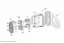
FIG. 1 is an exploded perspective view of a connector assembly;
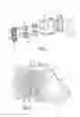
FIG. 2 is a cutaway side view of a connector assembly;
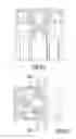
FIG. 3A is an end view of a female housing;
FIG. 3B is an end view of a female housing;
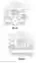
FIG. 4A is partial perspective view of the male terminal position assurance structure detailing the wedges formed thereon;
FIG. 4B is partial perspective view of the female terminal position assurance structure detailing the wedges formed thereon;
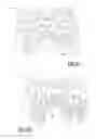
FIG. 5 is an end view of a male housing;
FIG. 6 is an end view of the female housing structure detailing the lance structures;
FIG. 6A is a sectional view of FIG. 6;
FIG. 6B is a partial end view of the female housing structure detailing the lance structures;
FIG. 6C is a sectional view of FIG. 6B;
FIG. 7 is an end view of the male housing structure detailing the lance structures;
FIG. 8 is a partial sectional view detailing the coaxial cavity and insertion of a coaxial terminal;
FIG. 9 is a top view of a male terminal position assurance structure including slots formed therein;
FIG. 10A is a view detailing insertion of a coaxial terminal and the interaction between the lance and wedges of the housing and terminal position assurance structure;
FIG. 10B is a view detailing insertion of a coaxial terminal and the bending of the lance;
FIG. 10C is a view detailing insertion of a coaxial terminal and the interaction between the lance and wedges of the housing and terminal position assurance structure when locked;
FIG. 11 is a partial perspective view of a male housing including panel lock members and a bridge and sidewall structure of the male housing;
FIG. 12a is a partial perspective view of a male housing including panel lock members and a bridge and sidewall structure of the male housing;
FIG. 12b is a view of FIG. 12a taken from the opposite side;
FIG. 13 is a partial perspective view of a female housing detailing the connector lock member including a bridge structure and sidewalls.
DETAILED DESCRIPTION OF THE PREFERRED EMBODIMENTS
Referring to the various figures, there is detailed a connector assembly 12 that may be utilized for wire routing through vehicle openings particularly through vehicle doors. The connector assembly 12 may include a male housing 14 that includes at least one coaxial cavity 16 and terminal cavities 18. At least one female housing 20 is shaped to be disposed in the male housing 14 when in a connected position. The at least one female housing 20 includes a corresponding coaxial cavity 16 relative to the male housing 14 and corresponding terminal cavities 18 relative to the male housing 14. At least one front loaded male terminal position assurance structure 24 is disposed in the male housing 14. At least one front loaded female terminal position assurance structure 26 is connected to the at least one female housing 20. The front loaded male and female terminal position assurance structures 24, 26 lock coaxial connections 28 and terminal connections 30 within the male and female housings 14, 20 when in the connected position.
In the depicted embodiments of FIGS. 1-3, the at least one female housing 20 includes two female housings 20. The female housings 20 may have differing numbers of terminal connections 30 with one including a coaxial cavity 16 in the depicted embodiment. The male housing 14 may be formed of a unitary structure and receives the two female housings 20. In this manner, the male housing 14 may be utilized in various vehicle platforms by switching the number of terminals within the female housings 20 while reusing the common male housing 14. Additionally, in the depicted embodiments of FIGS. 1-2 and 4, two male and female terminal position assurance structures 24, 26 are provided. It should be realized that various numbers of terminal connections or terminals 30 may be provided in the female housing 20 which will also have a corresponding male housing 14 and will also include a corresponding number of terminal position structures in the male and female terminal position assurance structures 24, 26. In one aspect, the connector assembly 12 may further include a grommet 32 attached to the male housing 14, as best seen in FIGS. 1 and 2.
In the depicted embodiments, the connector assembly 12 includes a coaxial cavity 16 and additional terminal cavities 18. The terminals may include various types of systems such as a Tyco Gen Y and FCI Apex type terminals. Additionally, in the depicted embodiments the two female housings 20 allow potential flexibility in design with differing numbers of terminals. In the depicted embodiment of FIG. 3A there is detailed an 18-terminal connector including a coaxial cavity 16 for receiving a coaxial terminal or connection 28 and 18 terminal connections 30 while in FIG. 3B, there is depicted a 25-terminal connector that does not include a coaxial cavity 16. It should be realized that various numbers of terminal connections 30 and coaxial connections 28 may be included.
Referring to FIG. 5, the male housing 14 includes a corresponding number of coaxial cavities 16 and terminal cavities 18 that align with the female housing 20 cavities as described above.
Referring to FIGS. 6 and 6A, the female housing 20 includes lance structures or lances 34 formed about the coaxial cavity 16. In one aspect, the lance structures 34 extend from a face 36 of the female housing 20 and are positioned radially about the coaxial cavity 16. In the depicted embodiment, two lance structures 34 are formed on the female housing 20. Similarly, as shown in FIG. 7, the male housing 14 includes lance structures 34 formed radially about the coaxial cavity 16 and again two lance structures 34 are shown in the depicted embodiment.
Referring to FIGS. 6B and 6C there is shown another position of the lances 34 on the female housing 20. The lances 34 as shown are positioned so as to be diametrically opposed to each other wherein the biasing force of one lance 34 is countered by the biasing force of the opposing lance 34. Accordingly, the coaxial terminal 28 is centered in the coaxial cavity 16, which helps ensure the coaxial terminal 28 is retained therein.
Referring to FIGS. 4A and 4B, the male terminal position assurance structures 24 and the female terminal position assurance structures 26 include wedges 38 formed thereon that correspond to a position of the coaxial cavity 16. In the depicted embodiment, the terminal position assurance structures 24, 26 include two wedges 38 formed thereon and extend from a face 40 of the terminal position assurance structures 24, 26. In one aspect, the wedges 38 interact with the lances 34 of the housings 14, 20 as will be described in more detail below.
Referring to FIG. 8, the coaxial cavity 16 of the male and female housings 14, 20 includes a cam structure 42 formed thereon that facilitates insertion and location of a coaxial terminal 28 into the coaxial cavity 16 and provides a temporary positioning of the coaxial terminal 28 before the terminals are locked in position as will be described in more detail below. As shown in the figure, the cam structure 42 may include at least one or multiple ramps or angles 44 formed on the surface 46 of the cavity 16 to facilitate insertion and location of the coaxial terminal 28 even when the terminal position assurance structures 24, 26 are in a pre-staged or removed position. As the coaxial terminal 28 is inserted into the cavity, it travels on the surface 46 and continues to a first ramp 44a which aligns and temporarily holds the coaxial terminal 28 in position within the cavity 16. As the coaxial terminal 28 is further inserted into the cavity it contacts a second ramp 44b that further aligns the coaxial terminal 28 within the cavity and temporarily holds the coaxial terminal in position.
Referring to FIG. 9, the male terminal position assurance structure 24 includes notches 48 formed thereon that control an insertion force connecting the male terminal position assurance structure 24 to the male housing 14. In this manner, a force can be regulated for connecting the male terminal position assurance structure 24 to the male housing 14 to assure fatigue or other types of failures do not occur.
Referring to FIGS. 10A-C, there is shown views of the interaction of a coaxial terminal 28 and housing 14 and terminal position assurance structure 24. When a coaxial terminal 28 is inserted into the coaxial cavity 16 of either the male or female housing 14, 20, the lances 34 of the housing 14, 20 and the wedges 38 of the terminal position assurance structures 24, 26 interact locking the coaxial terminal 28 into position. When the coaxial terminal 28 is inserted into the coaxial cavity 16 of the male or female housing 14, 20, the lances 34 begin in a starting position (FIG. 10A) and then bend allowing the terminal 28 to be pushed into the cavity (FIG. 10B). Next the lances 34 return to the starting position as the wedges 38 of the terminal position assurance structure 24, 26 slide beneath the lances 34 preventing the lance 34 from bending and locking the coaxial terminal 28 into position (FIG. 10C).
Referring to FIG. 11, the connector assembly 12 includes a male housing 14 having a plurality of panel lock members 50 locking the male housing 14 into an opening formed in a panel. The male housing 14 includes a bridge structure 52 formed thereon proximate the panel locks 50 preventing breakage of the panel locks 50. Additionally, the male housing 14 includes sidewalls 54 formed thereon proximate the panel locks 50 preventing deflection of the panel locks 50. Further, as best shown in FIGS. 12a and 12b, the panel locks 50 extend toward a rear face 56 of the housing 14 less than flush relative to the rear face 56 to minimize snagging of the panel lock members 50.
Referring to FIG. 13, the female housing 20 includes a connector lock 58 locking the female and male housings 14, 20. The female housing 20 includes a bridge structure 60 formed thereon proximate the connector lock 58 preventing breakage of the connector lock 58. Additionally, the female housing 20 includes sidewalls 62 formed thereon proximate the connector lock 58 to prevent deflection of the connector lock 58. Additionally, the connector lock 58 extends toward a rear face 64 of the female housing 20 less than flush relative to the rear face 64 minimizing snagging of the connector lock 58.
The above examples and embodiments are for illustrative purposes only and changes, modifications, and the like will be apparent to those skilled in the art and yet still fall within the scope of the invention. As such, the scope of the invention is defined by the claims.
Claims
I claim:1. A connector assembly comprising:
a male housing including at least one coaxial cavity and terminal cavities;
at least one female housing shaped to be disposed in the male housing when in a connected position, the at least one female housing including a corresponding coaxial cavity relative to the male housing and corresponding terminal cavities relative to the male housing;
at least one front loaded male terminal position assurance structure disposed in the male housing;
at least one front loaded female terminal position assurance structure connected to the at least one female housing; and
wherein the front loaded male and female terminal position assurance structures lock coaxial connections and the terminal connections within the male and female housings when in the connected position.
2. The connector assembly of claim 1 wherein the at least one female housing includes two female housings.
3. The connector assembly of claim 1 further including a grommet attached to the male housing.
4. The connector assembly of claim 1 wherein the male housing includes lance structures formed radially about the coaxial cavity.
5. The connector assembly of claim 1 wherein the male housing includes lance structures formed diametrically opposed to each other about the coaxial cavity.
6. The connector assembly of claim 1 wherein the male terminal position assurance structure includes wedges formed therein corresponding to a position of the coaxial cavity.
7. The connector assembly of claim 1 wherein the female housing includes lance structures formed radially about the coaxial cavity.
8. The connector assembly of claim 1 wherein the female housing includes lance structures formed diametrically opposed to each other about the coaxial cavity.
9. The connector assembly of claim 1 wherein the female terminal position assurance structure includes wedges formed therein corresponding to a position of the coaxial cavity.
10. The connector assembly of claim 1 wherein the coaxial cavity of the male and female housing includes a cam structure formed thereon aligning and holding a coaxial terminal within the coaxial cavity.
11. The connector assembly of claim 10 wherein the cam structure includes at least one ramp formed on a surface of the cavity holding and locating the coaxial terminal within the coaxial cavity.
12. The connector assembly of claim 1 wherein the male terminal position assurance structure includes notches formed thereon controlling an insertion force connecting the male terminal position assurance structure to the male housing.
13. The connector assembly of claim 1 wherein when a coaxial terminal is inserted into the coaxial cavity of the male housing lance structures of the male housing and wedges of the male terminal position assurance structure interact locking the coaxial terminal into position.
14. The connector assembly of claim 1 wherein when a coaxial terminal is inserted into the coaxial cavity of the female housing, lance structures of the female housing and wedges of the female terminal position assurance structure interact locking the coaxial terminal into position.
15. The connector assembly of claim 13 wherein when a coaxial terminal is inserted into the coaxial cavity of the male housing the lance structures begin in a starting position and then bend allowing the terminal to be pushed into the cavity and the lance structures then return to the starting position as the wedges of the male terminal position assurance structure slide beneath the lance structures preventing the lance structures from bending and locking the coaxial terminal into position.
16. The connector assembly of claim 14 wherein when a coaxial terminal is inserted into the coaxial cavity of the female housing the lance structures begin in a starting position and then bend allowing the terminal to be pushed into the cavity and the lance structures then return to the starting position as the wedges of the female terminal position assurance structure slide beneath the lance structures preventing the lance structures from bending and locking the coaxial terminal into position.
17. The connector assembly of claim 1 wherein the male housing includes a plurality of panel lock members locking the male housing into an opening and wherein the male housing includes a bridge structure formed thereon proximate the panel locks preventing breakage of the panel locks.
18. The connector assembly of claim 1 wherein the male housing includes a plurality of panel lock members locking the male housing into an opening and wherein the male housing includes sidewalls formed thereon proximate the panel locks preventing deflection of the panel locks.
19. The connector assembly of claim 1 wherein the male housing includes a plurality of panel lock members locking the male housing into an opening and wherein the panel locks extend toward a rear face of the housing less than flush relative to the rear face minimizing snagging of the panel lock members.
20. The connector assembly of claim 1 wherein the female housing includes a connector lock member locking the female and male housings and wherein the female housing includes a bridge structure formed thereon proximate the connector lock preventing breakage of the connector lock.
21. The connector assembly of claim 1 wherein the female housing includes a connector lock member locking the female and male housings and wherein the female housing includes sidewalls formed thereon proximate the connector lock preventing deflection of the connector lock.
22. The connector assembly of claim 1 wherein the female housing includes a connector lock member locking the female and male housings and wherein the connector lock extends toward a rear face of the housing less than flush relative to the rear face minimizing snagging of the connector lock member.
23. A connector assembly comprising:
a male housing including at least one coaxial cavity and terminal cavities;
at least one female housing shaped to be disposed in the male housing when in a connected position, the at least one female housing including a corresponding coaxial cavity relative to the male housing and corresponding terminal cavities relative to the male housing;
wherein the coaxial cavity of the male and female housing includes a cam structure formed thereon aligning and holding a coaxial terminal within the coaxial cavity.
24. The connector assembly of claim 23 wherein the cam structure includes at least one ramp formed on a surface of the cavity holding and locating the coaxial terminal within the coaxial cavity.
25. A connector assembly comprising:
a male housing including at least one coaxial cavity and terminal cavities, the male housing includes lance structures formed about the coaxial cavity;
at least one female housing shaped to be disposed in the male housing when in a connected position, the at least one female housing including a corresponding coaxial cavity relative to the male housing and corresponding terminal cavities relative to the male housing, the female housing includes lance structures formed about the coaxial cavity;
at least one front loaded male terminal position assurance structure disposed in the male housing, the male terminal position assurance structure including wedges formed therein corresponding to a position of the coaxial cavity;
at least one front loaded female terminal position assurance structure connected to the at least one female housing, the female terminal position assurance structure includes wedges formed therein corresponding to a position of the coaxial cavity; and
wherein when a coaxial terminal is inserted into the coaxial cavity of the male or female housing the lances of the male or female housing and the wedges of the male or female terminal position assurance structure interact locking the coaxial terminal into position.
Images & Drawings included:

Sources:
- United States Patent and Trademark Office - verify current appl. status at the USPTO↗
Recent applications in this class:
- » 20250174945 2025-05-29
SELF-PASSIVATING MATERIAL COMMUNICATION CABLE SYSTEM - » 20220037841 2022-02-03
Coaxial electrical connector - » 20190288464 2019-09-19
Electrical connection assembly with electrical connector mounted and overmolded on an electric cable, associated production method - » 20190052031 2019-02-14
Coaxial cable connector and coaxial connector device - » 20190052030 2019-02-14
Coaxial connector and coaxial connector device - » 20180131143 2018-05-10
Post-less, self-gripping connector for a coaxial cable - » 20140162493 2014-06-12
Coaxial cable connector and method of making same - » 20100112852 2010-05-06
Axial compression coaxial connector with grip surfaces - » 20050239327 2005-10-27
Device for electronically contacting an electrically conductive part of a high-frequency system
Recent applications for this Assignee:
- » 20250022628 2025-01-16
COPPER ALLOY WIRE, COVERED WIRE, COVERED WIRE WITH TERMINAL, AND METHOD FOR MANUFACTURING COPPER ALLOY WIRE - » 20240380133 2024-11-14
TERMINAL, TERMINAL-EQUIPPED ELECTRIC WIRE, AND CONNECTION STRUCTURE - » 20240112509 2024-04-04
VEHICLE - » 20240084425 2024-03-14
Aluminum alloy plate, terminal, electric wire with terminal, and bus bar - » 20220295631 2022-09-15
Flexible printed wiring board and battery wiring module - » 20220272839 2022-08-25
FLEXIBLE PRINTED WIRING BOARD, BATTERY WIRING MODULE, AND METHOD OF MANUFACTURING FLEXIBLE PRINTED WIRING BOARD - » 20220272836 2022-08-25
FLEXIBLE PRINTED WIRING BOARD AND BATTERY WIRING MODULE - » 20210362663 2021-11-25
BEAM MEMBER - » 20210327639 2021-10-21
Reactor - » 20210300270 2021-09-30
Power storage unit control device