MIDDLE/HIGH CARBON STEEL SHEET AND METHOD FOR MANUFACTURING SAME
US20170067132A1
2017-03-09
15/123,119
2015-03-09
Abstract:
A middle/high carbon steel sheet according to an aspect of the present invention is a steel sheet, in which composition thereof contains, by mass %, C: 0.10% to 1.50%, Si: 0.01% to 1.00%, Mn: 0.01% to 3.00%, P: 0.0001% to 0.1000%, and S: 0.0001% to 0.1000%, and a remainder consisting of Fe and impurities, in which the steel sheet has a structure in which a total volume percentage of a martensite, a bainite, a pearlite, and a residual austenite is equal to or lower than 5.0%, and a remainder thereof is a ferrite and carbides, in which a spheroidizing ratio of carbide particles is 70% to 99%, and in which a proportion of a number of the carbide particles including a crystal interface at which an orientation difference is equal to or greater than 5° in the carbide particles is equal to or lower than 20% of a total number of the carbide particles.
Inventors:
- Takashi ARAMAKI 2 🇯🇵 Kitakyushu-shi, Japan
- Kengo TAKEDA 2 🇯🇵 Kimitsu-shi, Japan
- Toshimasa TOMOKIYO 1 🇯🇵 Nagoya-shi, Japan
- Yasushi TSUKANO 2 🇯🇵 Kitakyushu-shi, Japan
Assignee:
- NIPPON STEEL & SUMITOMO METAL CORPORATION 876 🇯🇵 Tokyo, Japan
Interested in similar patents?
Get notified when new applications in this technology area are published.
Classification:
C22C38/008 » CPC further
Ferrous alloys, e.g. steel alloys containing tin
C22C38/005 » CPC further
Ferrous alloys, e.g. steel alloys containing rare earths, i.e. Sc, Y, Lanthanides
C22C38/002 » CPC further
Ferrous alloys, e.g. steel alloys containing In, Mg, or other elements not provided for in one single group -
C22C38/001 » CPC further
Ferrous alloys, e.g. steel alloys containing N
C21D8/0226 » CPC further
Modifying the physical properties by deformation combined with, or followed by, heat treatment during manufacturing of plates or strips characterised by the working steps Hot rolling
C21D8/0236 » CPC further
Modifying the physical properties by deformation combined with, or followed by, heat treatment during manufacturing of plates or strips characterised by the working steps Cold rolling
C21D8/0263 » CPC further
Modifying the physical properties by deformation combined with, or followed by, heat treatment during manufacturing of plates or strips characterised by the heat treatment following hot rolling
C21D2211/001 » CPC further
Microstructure comprising significant phases Austenite
C21D2211/002 » CPC further
Microstructure comprising significant phases Bainite
C21D2211/008 » CPC further
Microstructure comprising significant phases Martensite
C21D2211/009 » CPC further
Microstructure comprising significant phases Pearlite
C21D9/46 » CPC main
Heat treatment, e.g. annealing, hardening, quenching or tempering, adapted for particular articles; Furnaces therefor for sheet metals
C22C38/32 » CPC further
Ferrous alloys, e.g. steel alloys containing chromium with boron
C22C38/16 » CPC further
Ferrous alloys, e.g. steel alloys containing copper
C22C38/14 » CPC further
Ferrous alloys, e.g. steel alloys containing titanium or zirconium
C21D8/02 IPC
Modifying the physical properties by deformation combined with, or followed by, heat treatment during manufacturing of plates or strips
C22C38/08 » CPC further
Ferrous alloys, e.g. steel alloys containing nickel
C22C38/06 » CPC further
Ferrous alloys, e.g. steel alloys containing aluminium
C22C38/04 » CPC further
Ferrous alloys, e.g. steel alloys containing manganese
C22C38/02 » CPC further
Ferrous alloys, e.g. steel alloys containing silicon
C22C38/00 IPC
Ferrous alloys, e.g. steel alloys
C22C38/60 » CPC further
Ferrous alloys, e.g. steel alloys containing lead, selenium, tellurium, or antimony, or more than 0.04% by weight of sulfur
C22C38/12 » CPC further
Ferrous alloys, e.g. steel alloys containing tungsten, tantalum, molybdenum, vanadium, or niobium
Description
TECHNICAL FIELD OF THE INVENTION
The present invention relates to a middle/high carbon steel sheet exhibiting excellent reduction in area during shaping at a high strain rate and a method for manufacturing the same.
The present application claims priority on the basis of Japanese Patent Application No. 2014-045689, filed on Mar. 7, 2014, the content of which is incorporated herein.
RELATED ART
Middle/high carbon steel sheets are used as materials for drive system components such as chains, gears, and clutches in vehicles, saws, blades, and the like. Materials obtained by shaping steel strips of middle/high carbon steel or steel sheets cut out from the steel strips into predetermined shapes are shaped into component shapes by deformation processing such as deep drawing, hole expanding, thickening, or thinning. In cold forging in which each of processes is individually carried out or processes of multiple kinds are carried out at the same time, materials are partially shaped at a high strain rate of approximately 10/sec, and, for steel sheets that are used as materials, there is a demand for excellent formability, that is, excellent reduction in area even during distortion at a high strain rate.
Thus far, there have been a number of proposals regarding techniques that improve the reduction in area of middle/high carbon steel sheets (for example, refer to Patent Documents 1 to 6).
For example, Patent Document 1 discloses an invention of a method for manufacturing a middle/high carbon steel sheet having excellent deep drawability, in which finishing rolling is carried out on a hot-rolled steel sheet or an annealed steel sheet containing C: 0.20% by mass to 0.90% by mass using a work roller having a surface roughness Ra in a range of 0.20 μm to 1.50 μm in at least a final rolling path under conditions of the total rolling reduction being set in a range of 20% to 70%, and then finishing annealing is carried out. However, the technique disclosed by Patent Document 1 is a technique in which reduction in area is increased by improving the roughness of the steel sheet surface, but is not a technique in which reduction in area is increased by improving material quality by the control of the structure forms of steel products and thus does not always provide the desired effects of the invention.
Furthermore, Patent Document 2 discloses an invention of a high-roughness high carbon steel sheet having excellent workability, including C: 0.6% by mass to 1.3% by mass, Si: 0.5% by mass or less, Mn: 0.2% by mass to 1.0% by mass, P: 0.02% by mass or less, and S: 0.01% by mass or less with a remainder substantially having a composition of Fe, in which, by adjustment of hot-rolling conditions, cold-rolling conditions, and annealing conditions, the maximum length of carbides is set to be equal to or shorter than 5.0 μm, the carbide spheroidizing ratio is set to be equal to or higher than 90%, the volume of spherical carbides having a grain size of equal to or larger than 1.0 μm is set to be equal to or higher than 20% of the total spherical carbide volume, and the high carbon steel sheet is made up of carbides and equiaxial ferrite.
Patent Document 3 discloses an invention of middle/high carbon steel exhibiting excellent reduction in size, in which the C content is in a range of 0.10% by mass to 0.90% by mass, and a structure in which carbides are dispersed in ferrite so that a ferrite intergranular abundance (F value) of the carbides reaches equal to or higher than 30% is formed.
Patent Document 4 discloses an invention of a high carbon cold-rolled steel strip which is slightly anisotropic in a deep drawn surface, having a steel composition of C: 0.25% to 0.75%, in which the average grain size of carbides in steel is equal to or larger than 0.5 μm, the spheroidizing ratio is equal to or higher than 90%, and a texture satisfies an expression “(222)/(200)≧6-8.0×C (%)”.
Patent Document 5 discloses an invention of a high carbon steel strip which has favorable deep drawability and, furthermore, is capable of imparting high strength or excellent wear resistance, in which the C content is in a range of 0.20% by mass to 0.70% by mass, and equal to or higher than 50% by area of cementite in the steel is graphitized.
Patent Document 6 discloses a technique of a method for manufacturing a high carbon cold-rolled steel sheet having excellent formability, in which high carbon steel containing C: 0.1% to 0.65%, Si: 0.01% to 0.3%, Mn: 0.4% to 2%, sol. Al: 0.01% to 0.1%, N: 0.002% to 0.008%, B: 0.0005% to 0.005%, Cr: 0 to 0.5, and Mo: 0 to 0.1 is hot-rolled, is coiled at 300° C. to 520° C., is box-annealed at 650° C. to (Ac1-10°) C., is cold-rolled at a rolling reduction in a range of 40% to 80%, and is box-annealed at 650° C. to (Ac1-10°) C.
However, none of the above-described patent documents discloses anything about knowledge and techniques that suppress the cracking of cementite in steel products, which occurs during shaping at a high strain rate, and a decrease in reduction in area caused by the growth and joining of voids initiated due to the initiation of cracks.
PRIOR ART DOCUMENT
Patent Document
[Patent Document 1] Japanese Unexamined Patent Application, First Publication No. 2003-293042
[Patent Document 2] Japanese Unexamined Patent Application, First Publication No. 2003-147485
[Patent Document 3] Japanese Unexamined Patent Application, First Publication No. 2002-155339
[Patent Document 4] Japanese Unexamined Patent Application, First Publication No. 2000-328172
[Patent Document 5] Japanese Unexamined Patent Application, First Publication No. H06-108158
[Patent Document 6] Japanese Unexamined Patent Application, First Publication No. H11-61272
DISCLOSURE OF THE INVENTION
Problems to be Solved by the Invention
The present invention has been made in consideration of the above-described circumstances, and an object of the present invention is to provide a middle/high carbon steel sheet exhibiting excellent reduction in area during shaping at a high strain rate and a method for manufacturing the same.
Means for Solving the Problem
The present inventors carried out intensive studies regarding methods for achieving the above-described object. As a result, the present inventors found that cracks (voids) forming at carbides during distortion propagate and join together, and thus reduction in area is decreased during distortion at a high strain rate. Furthermore, the present inventors found that cracks forming at carbides are initiated from crystal interfaces present in carbide particles which have been considered as a single particle in the related art. The present inventors found that, when the amount of crystal interfaces in carbide particles is decreased, it is possible to obtain a middle/high carbon steel sheet which exhibits excellent reduction in area even during distortion at a high strain rate and, furthermore, exhibits excellent formability in cold forging in which deformation processing such as deep drawing, hole expanding, thickening, or thinning is carried out or multiple kinds thereof are carried out at the same time.
In addition, the present inventors repeated a variety of studies and thus found that it is difficult to manufacture steel sheets having the above-described characteristics in a case in which efforts are made to separately find appropriate hot-rolling conditions, annealing conditions, and the like, and the steel sheets can only be manufactured by achieving optimization by so-called collective processing such as hot-rolling and annealing processing, and completed the present invention.
The outline of the present invention is as described below.
(1) An aspect of the present invention provides a middle/high carbon steel sheet, in which composition thereof contains, by mass %, C: 0.10% to 1.50%, Si: 0.01% to 1.00%, Mn: 0.01% to 3.00%, P: 0.0001% to 0.1000%, and S: 0.0001% to 0.1000%, and a remainder consisting of Fe and impurities, in which the steel sheet has a structure in which a total volume percentage of a martensite, a bainite, a pearlite, and a residual austenite is equal to or lower than 5.0%, and a remainder thereof is a ferrite and carbides, in which the spheroidizing ratio of carbide particles is 70% to 99%, and in which a proportion of a number of the carbide particles including a crystal interface at which an orientation difference is equal to or greater than 5° in the carbide particles is equal to or lower than 20% of a total number of the carbide particles.
(2) The middle/high carbon steel sheet according to (1), in which the composition of the steel sheet may further include, by mass %, one or more selected from the group consisting of Al: 0.001% to 0.500%, N: 0.0001% to 0.0500%, O: 0.0001% to 0.0500%, Cr: 0.001% to 2.00%, Mo: 0.001% to 2.000%, Ni: 0.001% to 2.00%, Cu: 0.001% to 1.000%, Nb: 0.001% to 1.000%, V: 0.001% to 1.000%, Ti: 0.001% to 1.000%, B: 0.0001% to 0.0500%, W: 0.001% to 1.000%, Ta: 0.001% to 1.000%, Sn: 0.001% to 0.020%, Sb: 0.001% to 0.020%, As: 0.001% to 0.020%, Mg: 0.0001% to 0.0200%, Ca: 0.001% to 0.020%, Y: 0.001% to 0.020%, Zr: 0.001% to 0.020%, La: 0.001% to 0.020%, and Ce: 0.001% to 0.020%.
(3) Another aspect of the present invention provides a method for manufacturing a middle/high carbon steel sheet, in which, when a billet having the composition according to (1) or (2) is directly hot-rolled or temporary cooled, heated, and hot-rolled, finish hot-rolling is completed in a temperature region of 600° C. to 1,000° C., the hot-rolled steel sheet coiled at 350° C. to 700° is box-annealed, cold-rolling of 10% to 80% is carried out, and then cold-rolled-sheet-annealing is carried out at an annealing temperature of 650° C. to 780° C. for a retention time of 30 to 1,800 seconds in a continuous annealing line.
Effects of the Invention
According to the present invention, it is possible to provide a middle/high carbon steel sheet exhibiting excellent reduction in area during shaping at a high strain rate and a method for manufacturing the same.
BRIEF DESCRIPTION OF THE DRAWING(S)
FIG. 1 is a view showing a shape of a test specimen used for measuring reduction in area at a high strain rate.
FIG. 2 is a view showing an appearance in which cracks are initiated from crystal interfaces present in carbide particles during distortion
FIG. 3 is a view showing a relationship between a proportion of the number of carbide particles including a crystal interface and reduction in area during a tensile test at a high strain rate.
EMBODIMENT(S) OF THE INVENTION
Hereinafter, the present embodiment will be described in detail.
First, the reasons for limiting the chemical composition of a steel sheet according to the present embodiment will be described. Here, regarding the composition, “%” represents “mass %”.
(C: 0.10% to 1.50%)
C is an element that increases the strength of steel by a heat treatment of quenching. Middle/high carbon steel sheets ensure strength or toughness necessary for components by heat treatments such as quenching and quenching and tempering which are carried out after shaping and before the use of the steel sheets as materials for drive system components such as chains, gears, and clutches in vehicles, saws, blades, and the like. When the C content is lower than 0.10%, the strength cannot be increased by quenching, and thus the lower limit of the C content is set to 0.10%. On the other hand, when the C content exceeds 1.50%, after cold-rolling and annealing, the proportion of the number of carbides including a crystal interface in the particle increases, and reduction in area is decreased at a high strain rate, and thus the upper limit of the C content is set to 1.50%. More preferably, the C content is in a range of 0.15% to 1.30%.
(Si: 0.01% to 1.00%)
Si is an element that acts as a deoxidizing agent and suppresses the coarsening and joining of carbide particles during hot-rolled-sheet-annealing and cold-rolled-sheet-annealing. In a process of the Ostwald growth of carbide particles during cold-rolled-sheet-annealing, when two or more particles that are adjacent to each other come into contact with each other, crystal interfaces are introduced into the carbide particles. During the distortion of the steel sheet, the crystal interfaces in the carbide particles serve as the starting points of cracks. In order to suppress the above-described phenomenon, it is necessary to decrease the growth rate of carbides during hot-rolled-sheet-annealing and cold-rolled-sheet-annealing. One of the typical elements that decrease the growth rate of carbides during hot-rolled-sheet-annealing and cold-rolled-sheet-annealing is Si. When the Si content is lower than 0.01%, the above-described effects cannot be obtained, and thus the lower limit of the Si content is set to 0.01%. On the other hand, when the Si content exceeds 1.00%, ferrite becomes prone to cleavage fracture, and reduction in area is decreased at a high strain rate, and thus the upper limit of the Si content is set to 1.00%. The Si content is more preferably 0.05% to 0.80% and still more preferably 0.08% to 0.50%.
(Mn: 0.01% to 3.00%)
Mn is, similar to Si, an element that suppresses the coarsening and joining of carbide particles during hot-rolled-sheet-annealing and cold-rolled-sheet-annealing. When the Mn content is lower than 0.01%, the above-described effects cannot be obtained, and thus the lower limit of the Mn content is set to 0.01%. On the other hand, when the Mn content exceeds 3.00%, it becomes difficult for carbides to spheroidize during hot-rolled-sheet-annealing and cold-rolled-sheet-annealing, cracks are initiated from needle-like carbides as starting points during distortion at a high strain rate, and reduction in area decreases. Therefore, the upper limit of the Mn content is set to 3.00%. The Mn content is more preferably 0.30% to 2.50% and still more preferably 0.50% to 1.50%.
(P: 0.0001% to 0.1000%)
P is an impurity element that embrittles grain boundaries of ferrite. The P content is preferably lower; however, in a case in which steel is highly purified by setting the P content to be lower than 0.0001% in refining, a time necessary for refining becomes long, and manufacturing costs are significantly increased, and thus the lower limit of the P content is set to 0.0001%. On the other hand, when the P content exceeds 0.1000%, cracks are significantly initiated from grain boundaries of ferrite during distortion at a high strain rate, and reduction in area is significantly decreased, and thus the upper limit of the P content is set to 0.1000%. The P content is more preferably 0.0010% to 0.0500% and still more preferably 0.0020% to 0.0300%.
(S: 0.0001% to 0.1000%)
S is an impurity element that forms non-metallic inclusions such as MnS, and non-metallic inclusions act as starting points for the initiation of cracks during distortion at a high strain rate, and thus the S content is preferably lower. However, a decrease in the S content to lower than 0.0001% leads to a significant increase in refining costs, and thus the lower limit of the S content is set to 0.0001%. On the other hand, when higher than 0.1000% of S is included, reduction in area is significantly decreased, and thus the upper limit of the S content is set to equal to or lower than 0.1000%. The S content is more preferably 0.0003% to 0.0300%.
In the present embodiment, the above-described composition is the base elements of the steel sheet; however, it is also possible to further, optionally, add one or two or more selected from the elements described below in order to improve the mechanical characteristics of the steel sheet. Here, the elements described below do not need to be essentially included, and thus the lower limit values of the elements described below are 0%.
(Al: Preferably 0.001% to 0.500%)
Al is an element that serves as a deoxidizing agent of steel. When the Al content is lower than 0.001%, effects of the inclusion of Al cannot be sufficiently obtained, and thus the lower limit of the Al content may be set to 0.001%. On the other hand, when the Al content exceeds 0.500%, grain boundaries of ferrite are embrittled, and reduction in area during distortion at a high strain rate is decreased. Therefore, the upper limit of the Al content may be set to 0.500%. The Al content is more preferably 0.005% to 0.300% and still more preferably 0.010% to 0.100%.
(N: Preferably 0.0001% to 0.0500%)
N is an element that accelerates the bainite transformation of steel. In addition, N causes ferrite to embrittle when a large amount of N is included. The N content is preferably lower, but a decrease in the N content to lower than 0.0001% leads to an increase in refining costs, and thus the lower limit of the N content may be set to 0.0001%. On the other hand, when the N content exceeds 0.0500%, the cracking of ferrite is caused during distortion at a high strain rate, and thus the upper limit of the N content may be set to 0.0500%. The N content is more preferably 0.0010% to 0.0250% and still more preferably n 0.0020% to 0.0100%.
(O: Preferably 0.0001% to 0.0500%)
O is an element that accelerates the formation of coarse oxides in steel when a large amount of O is included, and thus the O content is preferably lower. However, a decrease in the O content to lower than 0.0001% leads to an increase in refining costs, and thus the lower limit of the O content may be set to 0.0001%. On the other hand, when the O content exceeds 0.0500%, coarse oxides are formed in steel, and cracks are initiated from the coarse oxides as starting points during distortion at a high strain rate, and thus the upper limit of the O content may be set to 0.0500%. The O content is more preferably 0.0005% to 0.0250% and still more preferably 0.0010% to 0.0100%.
(Cr: Preferably 0.001% to 2.000%)
Cr is an element that, similar to Si and Mn, suppresses the coarsening and joining of carbide particles during hot-rolled-sheet-annealing and cold-rolled-sheet-annealing. However, when the Cr content is lower than 0.001%, the above-described effect cannot be obtained, and thus the lower limit of the Cr content may be set to 0.001%. On the other hand, when the Cr content exceeds 2.000%, it becomes difficult for carbides to spheroidize during hot-rolled-sheet-annealing and cold-rolled-sheet-annealing, cracks are initiated from needle-like carbides as starting points during distortion at a high strain rate, and reduction in area is decreased, and thus the upper limit of the Cr content may be set to 2.000%. The Cr content is more preferably 0.005% to 1.500% and still more preferably 0.010% to 1.300%.
(Mo: Preferably 0.001% to 2.000%)
Mo is an element that, similar to Si, Mn, and Cr, suppresses the coarsening and joining of carbide particles during hot-rolled-sheet-annealing and cold-rolled-sheet-annealing. When the Mo content is lower than 0.001%, the above-described effect cannot be obtained, and thus the lower limit of the Mo content may be set to 0.001%. On the other hand, when the Mo content exceeds 2.000%, it becomes difficult for carbides to spheroidize during hot-rolled-sheet-annealing and cold-rolled-sheet-annealing, cracks are initiated from needle-like carbides as starting points during distortion at a high strain rate, and reduction in area is decreased, and thus the upper limit of the Mo content may be set to 2.000%. The Mo content is more preferably 0.005% to 1.900% and still more preferably 0.008% to 0.800%.
(Ni: Preferably 0.001% to 2.000%)
Ni is an element effective for improving the toughness of components and improving hardenability. In order to effectively exhibit the above-described effect, equal to or higher than 0.001% of Ni is preferably included. On the other hand, when the Ni content exceeds 2.000%, it becomes difficult for carbides to spheroidize during hot-rolled-sheet-annealing and cold-rolled-sheet-annealing, cracks are initiated from needle-like carbides as starting points during distortion at a high strain rate, and reduction in area is decreased, and thus the upper limit of the Ni content may be set to 2.000%. The Ni content is more preferably 0.005% to 1.500% and still more preferably 0.005% to 0.700%.
(Cu: Preferably 0.001% to 1.000%)
Cu is an element that increases the strengths of steel products by forming fine precipitates. In order to effectively exhibit the effect of an increase in strength, equal to or higher than 0.001% of Cu is preferably included. On the other hand, when the Cu content exceeds 1.00%, it becomes difficult for carbides to spheroidize during hot-rolled-sheet-annealing and cold-rolled-sheet-annealing, cracks are initiated from needle-like carbides as starting points during distortion at a high strain rate, and reduction in area is decreased, and thus the upper limit of the Cu content may be set to 1.00%. The Cu content is more preferably 0.003% to 0.500% and still more preferably 0.005% to 0.200%.
(Nb: Preferably 0.001% to 1.000%)
Nb is an element that forms carbonitrides and suppresses the coarsening and joining of carbide particles during hot-rolled-sheet-annealing and cold-rolled-sheet-annealing. However, when the Nb content is lower than 0.001%, the above-described effect cannot be obtained, and thus the lower limit of the Nb content may be set to 0.001%. On the other hand, when the Nb content exceeds 1.000%, it becomes difficult for carbides to spheroidize during hot-rolled-sheet-annealing and cold-rolled-sheet-annealing, cracks are initiated from needle-like carbides as starting points during distortion at a high strain rate, and reduction in area is decreased, and thus the upper limit of the Nb content may be set to 1.000%. The Nb content is more preferably 0.005% to 0.600% and still more preferably 0.008% to 0.200%.
(V: Preferably 0.001% to 1.000%)
V is also an element that, similar to Nb, forms carbonitrides and suppresses the coarsening and joining of carbide particles during hot-rolled-sheet-annealing and cold-rolled-sheet-annealing. When the V content is lower than 0.001%, the above-described effect cannot be obtained, and thus the lower limit of the V content may be set to 0.001%. On the other hand, when the V content exceeds 1.000%, it becomes difficult for carbides to spheroidize during hot-rolled-sheet-annealing and cold-rolled-sheet-annealing, cracks are initiated from needle-like carbides as starting points during distortion at a high strain rate, and reduction in area is decreased, and thus the upper limit of the V content may be set to 1.000%. The V content is more preferably 0.001% 0.750% and still more preferably 0.001% to 0.250%.
(Ti: Preferably 0.001% to 1.000%)
Ti is also an element that, similar to Nb and V, forms carbonitrides and suppresses the coarsening and joining of carbide particles during hot-rolled-sheet-annealing and cold-rolled-sheet-annealing. When the Ti content is lower than 0.001%, the above-described effect cannot be obtained, and thus the lower limit of the Ti content may be set to 0.001%. On the other hand, when the Ti content exceeds 1.000%, it becomes difficult for carbides to spheroidize during hot-rolled-sheet-annealing and cold-rolled-sheet-annealing, cracks are initiated from needle-like carbides as starting points during distortion at a high strain rate, and reduction in area is decreased, and thus the upper limit of the Ti content may be set to 1.000%. The Ti content is more preferably 0.001% to 0.500% and still more preferably 0.003% to 0.150%.
(B: Preferably 0.0001% to 0.0500%)
B is an element that improves hardenability during a heat treatment of components. When the B content is lower than 0.0001%, the above-described effect cannot be obtained, and thus the lower limit of the B content may be set to 0.0001%. When the B content exceeds 0.0500%, coarse Fe—B—C compounds are generated and serve as starting points during distortion at a high strain rate, and reduction in area is decreased, and thus the upper limit of the B content may be set to 0.0500%. The B content is more preferably 0.0005% to 0.0300% and still more preferably 0.0010% to 0.0100%.
(W: Preferably 0.001% to 1.000%)
W is also an element that, similar to Nb, V, and Ti, forms carbonitrides and suppresses the coarsening and joining of carbide particles during hot-rolled-sheet-annealing and cold-rolled-sheet-annealing. When the W content is lower than 0.001%, the above-described effect cannot be obtained, and thus the lower limit of the W content may be set to 0.001%. On the other hand, when the W content exceeds 1.000%, it becomes difficult for carbides to spheroidize during hot-rolled-sheet-annealing and cold-rolled-sheet-annealing, cracks are initiated from needle-like carbides as starting points of cracks during distortion at a high strain rate, and reduction in area is decreased, and thus the upper limit of the W content may be set to 1.000%. The W content is more preferably 0.001% to 0.450% and still more preferably 0.001% to 0.160%.
(Ta: Preferably 0.001% to 1.000%)
Ta is also an element that, similar to Nb, V, Ti, and W, forms carbonitrides and suppresses the coarsening and joining of carbide particles during hot-rolled-sheet-annealing and cold-rolled-sheet-annealing. When the Ta content is lower than 0.001%, the above-described effect cannot be obtained, and thus the lower limit of the Ta content may be set to 0.001%. On the other hand, when the Ta content exceeds 1.000%, it becomes difficult for carbides to spheroidize during hot-rolled-sheet-annealing and cold-rolled-sheet-annealing, cracks are initiated from needle-like carbides as starting points during distortion at a high strain rate, and reduction in area is decreased, and thus the upper limit of the Ta content may be set to 1.000%. The Ta content is more preferably 0.001% to 0.750% and still more preferably 0.001% to 0.150%.
(Sn: Preferably 0.001% to 0.020%)
Sn is an element included in steel in a case in which scraps are used as a steel raw material, and the Sn content is preferably lower. In a case in which the Sn content is decreased to lower than 0.001%, refining costs are increased, and thus the lower limit of the Sn content may be set to 0.001%. In addition, in a case in which the Sn content exceeds 0.020%, ferrite embrittles, and reduction in area is decreased during distortion at a high strain rate, and thus the upper limit of the Sn content may be set to 0.020%. The Sn content is more preferably 0.001% to 0.015% and still more preferably 0.001% to 0.010%.
(Sb: Preferably 0.001% to 0.020%)
Sb is, similar to Sb, an element included in steel in a case in which scraps are used as a steel raw material, and the Sb content is preferably lower. In a case in which the Sb content is decreased to lower than 0.001%, refining costs are increased, and thus the lower limit of the Sb content may be set to 0.001%. In addition, in a case in which the Sb content exceeds 0.020%, ferrite embrittles, and reduction in area is decreased during distortion at a high strain rate, and thus the upper limit of the Sb content may be set to 0.020%. The Sb content is more preferably 0.001% to 0.015% and still more preferably 0.001% to 0.011%.
(As: Preferably 0.001% to 0.020%)
As is, similar to Sn and Sb, an element included in steel in a case in which scraps are used as a steel raw material, and the As content is preferably lower. In a case in which the As content is decreased to lower than 0.001%, refining costs are increased, and thus the lower limit of the As content may be set to 0.001%. In addition, in a case in which the As content exceeds 0.020%, ferrite embrittles, and reduction in area is decreased during distortion at a high strain rate, and thus the upper limit of the As content may be set to 0.020%. The As content is more preferably 0.001% to 0.015% and still more preferably 0.001% to 0.007%.
(Mg: Preferably 0.0001% to 0.0200%)
Mg is an element capable of controlling the form of sulfides even when the content thereof is low and can be included as necessary. When the Mg content is lower than 0.0001%, the above-described effect cannot be obtained, and thus the lower limit of the Mg content may be set to 0.0001%. On the other hand, in a case in which Mg is excessively included, grain boundaries of ferrite are embrittled, and reduction in area during distortion at a high strain rate is decreased, and thus the upper limit of the Mg content may be set to 0.0200%. The Mg content is more preferably 0.0001% to 0.0150% and still more preferably 0.0001% to 0.0075%.
(Ca: Preferably 0.001% to 0.020%)
Ca is, similar to Mg, an element capable of controlling the form of sulfides even when the content thereof is low and can be included as necessary. When the Ca content is lower than 0.001%, the above-described effect cannot be obtained, and thus the lower limit of the Ca content may be set to 0.001%. On the other hand, in a case in which Ca is excessively included, grain boundaries of ferrite are embrittled, and reduction in area during distortion at a high strain rate is decreased, and thus the upper limit of the Ca content may be set to 0.020%. The Ca content is more preferably 0.001% to 0.015% and still more preferably 0.001% to 0.010%.
(Y: Preferably 0.001% to 0.020%)
Y is, similar to Mg and Ca, an element capable of controlling the form of sulfides even when the content thereof is low and can be included as necessary. When the Y content is lower than 0.001%, the above-described effect cannot be obtained, and thus the lower limit of the Y content may be set to 0.001%. On the other hand, in a case in which Y is excessively included, grain boundaries of ferrite are embrittled, and reduction in area during distortion at a high strain rate is decreased, and thus the upper limit of the Y content may be set to 0.020%. The Y content is more preferably 0.001% to 0.015% and still more preferably 0.001% to 0.009%.
(Zr: Preferably 0.001% to 0.020%)
Zr is, similar to Mg, Ca, and Y, an element capable of controlling the form of sulfides even when the content thereof is low and can be included as necessary. When the Zr content is lower than 0.001%, the above-described effect cannot be obtained, and thus the lower limit of the Zr content may be set to 0.001%. On the other hand, in a case in which Zr is excessively included, grain boundaries of ferrite are embrittled, and reduction in area during distortion at a high strain rate is decreased, and thus the upper limit of the Zr content may be set to 0.020%. The Zr content is more preferably equal to or lower than 0.015% and still more preferably equal to or lower than 0.010%.
(La: Preferably 0.001% to 0.020%)
La is, similar to Mg, Ca, Y, and Zr, an element capable of controlling the form of sulfides even when the content thereof is low and can be included as necessary. When the La content is lower than 0.001%, the above-described effect cannot be obtained, and thus the lower limit of the La content may be set to 0.001%. On the other hand, in a case in which La is excessively included, grain boundaries of ferrite are embrittled, and reduction in area during distortion at a high strain rate is decreased, and thus the upper limit of the La content may be set to 0.020%. The La content is more preferably 0.001% to 0.015% and still more preferably 0.001% to 0.010%.
(Ce: Preferably 0.001% to 0.020%)
Ce is, similar to Mg, Ca, Y, Zr, and La, an element capable of controlling the form of sulfides even when the content thereof is low and can be included as necessary. When the Ce content is lower than 0.001%, the above-described effect cannot be obtained, and thus the lower limit of the Ce content may be set to 0.001%. On the other hand, in a case in which Ce is excessively included, grain boundaries of ferrite are embrittled, and reduction in area during distortion at a high strain rate is decreased, and thus the upper limit of the Ce content may be set to 0.020%. The Ce content is more preferably 0.001% to 0.015% and still more preferably 0.001% to 0.010%.
Meanwhile, in the steel sheet according to the present embodiment, the remainder of the composition described above is Fe and impurities.
The steel sheet according to the present embodiment does not only have the above-described composition but is also subjected to optimal hot-rolling and annealing, and thus the steel sheet has a structure in which ferrite and carbides are main bodies, the total volume percentage of martensite, bainite, pearlite, and residual austenite is equal to or lower than 5.0%, the spheroidizing ratio of carbide particles is 70% to 99%, and the proportion of the number of the carbide particles including a crystal interface at which an orientation difference is equal to or greater than 5° in the carbide particles is equal to or lower than 20% of the total number of the carbide particles. Due to these characteristics, it is possible to obtain steel sheets having excellent formability when deformation processing such as reduction in area, hole expanding, thickening, or thinning or cold forging in which the above-described processes are combined together is carried out at a high strain rate. This is new knowledge that the present inventors found.
Steel according to the present embodiment has a structure of substantially ferrite and carbides. Meanwhile, carbides refer to not only cementite (Fe3C) which is a compound of iron and carbon but also a compound in which Fe atoms in cementite are substituted with alloy elements such as Mn and Cr and alloy carbides (M23C6, M6C, MC; here, M represents Fe and other alloy elements). Martensite, bainite, pearlite, and residual austenite are preferably not included in the structure, and, in a case in which they are included, the total volume percentage is set to equal to or lower than 5.0%. The lower limit of the total amount of martensite, bainite, pearlite, and residual austenite is not regulated. In a case in which no structures thereof are detected in a structure observation at a magnification of 3,000 times using a scanning electron microscope, which will be described below, the total amount of martensite, bainite, pearlite, and residual austenite is considered as 0.0% by volume, and thus the lower limit of the total amount of martensite, bainite, pearlite, and residual austenite may be set to 0.0%.
The reasons for limiting the total amount of martensite, bainite, pearlite, and residual austenite will be described. Martensite, bainite, pearlite, and residual austenite which are the regulation subjects in the present embodiment are structures generated from austenite in a process in which the steel sheet is heated to a two-phase region of ferrite and austenite during cold-rolled-sheet-annealing and then is cooled to room temperature. Therefore, martensite, bainite, and pearlite are located in grain boundaries of ferrite, and residual austenite is present in lath interfaces or block boundaries between martensite and bainite. First, when austenite transforms to martensite, bainite, or pearlite, the volume expands, and thus stress remains in grain boundaries of ferrite. Stress locally remaining in the grain boundaries of ferrite accelerate the initiation of voids in the vicinities of the grain boundaries during distortion of the steel sheet due to stress loading, and thus stress remaining the grain boundaries of ferrite leads to a decrease in reduction in area during distortion at a high strain rate. In addition, residual austenite turns into martensite during the distortion of the steel sheet by processing-induced transformation caused therein, and thus an increase in stress in the ferrite grain boundaries is further increased, and a decrease in reduction in area is promoted. For the above-described reasons, in order to improve reduction in area during distortion at a high strain rate, it is preferable to set the structure of the steel sheet to a structure of substantially ferrite and carbides and to include no martensite, bainite, pearlite, and residual austenite in the structure, and, in a case in which they are included, it becomes essential to set the total volume percentage of martensite, bainite, pearlite, and residual austenite to equal to or lower than 5.0%. Furthermore, in a case in which pearlitic transformation is caused, the proportion of needle-like carbides also increases. The influences of needle-like carbides will be described below. Meanwhile, in carbides, phase transformation does not occur, and stress does not accumulate between carbides and base metal, and thus it is possible to limit a decrease in reduction in area.
Next, the reasons for setting the spheroidizing ratio of carbides to 70% to 99% will be described. When the spheroidizing ratio of carbides is lower than 70%, stress accumulates at needle-like carbides, carbides crack, thus, voids are initiated, and voids joined together form a broken surface, and thus reduction in area during distortion at a high strain rate is decreased. Therefore, the lower limit of the spheroidizing ratio of carbides is set to 70%. Meanwhile, the spheroidizing ratio is desirably higher; however, in order to control the spheroidizing ratio to be 100%, it is necessary to carry out annealing for an extremely long period of time, which leads to an increase in manufacturing costs, and thus the upper limit of the spheroidizing ratio is desirably lower than 100% and is set to equal to or lower than 99%.
Furthermore, the reasons for setting the proportion of the number of carbide particles including a crystal interface at which a crystal orientation difference is equal to or greater than 5° in carbide particles to be equal to or lower than 20% of the total number of carbide particles will be described. Cracking of carbides during distortion mainly initiates from crystal interfaces at which a crystal orientation difference is equal to or greater than 5° which are present in the carbides which have been considered as a single particle in the related art. During distortion at a high strain rate, voids are initiated due to the cracking of carbides at crystal interfaces, the voids join together, and a broken surface is formed, whereby reduction in area is decreased. The proportion of carbides including a crystal interface at which a crystal orientation difference is equal to or greater than 5° is preferably lower; however, in order to control the proportion of the number of carbides including a crystal interface at which a crystal orientation difference is equal to or greater than 5° to be lower than 0.1% of the total number of carbide particles, collective quality design management becomes essential in continuous forging, hot-rolling, hot-rolled-sheet-annealing, cold-rolling, and cold-rolled-sheet-annealing, and the yield is decreased, and thus the lower limit of the proportion of the number of carbides including a crystal interface at which a crystal orientation difference is equal to or greater than 5° of the total number of carbide particles is preferably set to 0.1% and more preferably set to 0.2%. In addition, in a case in which the proportion of the number of carbides including a crystal interface at which an orientation difference is equal to or greater than 5° in the total number of carbide particles exceeds 20%, reduction in area is significantly decreased during distortion at a high strain rate, and thus the upper limit of the proportion of the number thereof is set to 20% and is more preferably 15% and still more preferably 10%.
Subsequently, a method for observing and measuring the structure regulated above will be described.
Ferrite, carbides, martensite, bainite, and pearlite are observed using a scanning electron microscope. Before observation, samples for structural observation are wet-polished using Emery paper and are polished using diamond abrasive grains having an average particle size of 1 μm, thereby finishing the observed sections to be mirror-like surfaces. Next, the observed sections are etched using a 3% nitric acid-alcohol solution. Regarding the observation magnification, a magnification at which determination of the respective structures of ferrite, carbides, martensite, bainite, and pearlite becomes possible is selected in a range of 1,000 times to 10,000 times. In the present embodiment, a magnification of 3,000 times was selected. At the selected magnification, 30 μm×40 μm visual fields randomly taken from a quarter thickness layer are captured 16 times. The volume percentages of the respective structures are obtained using a point count method. On captured structural photographs, grid lines are drawn vertically and horizontally at intervals of 2 μm, the numbers of the structures at the intersections of the grid lines are respectively counted, and the proportions of the respective structures per the captured photograph are measured from the proportions of the numbers of the respective structures. After that, the average values of the measurement results of the proportions of the respective structures according to all of the 16 structural photographs are obtained as the volume percentages of the structures in the respective samples.
Meanwhile, martensite and bainite are differentiated on the basis of the presence or absence of fine carbides in the structure. A structure which is mainly located on a grain boundary of ferrite and does not include carbides is martensite, and a structure including carbides is bainite. In addition, in a case in which martensite is tempered martensite, since tempered martensite includes carbides therein, there is a possibility that martensite may be misidentified as bainite. However, in steel according to the present embodiment, it has been clarified that, when the total volume percentage of martensite, bainite, pearlite, and residual austenite is set to be 5%, favorable reduction in area can be obtained, and thus the influence of the misidentification of martensite and bainite having influences on the final form of the steel according to the present embodiment is extremely small. Meanwhile, the volume percentage of ferrite is desirably set to equal to or higher than 70%.
The volume percentage of residual austenite is measured by X-ray diffraction. A strained layer on the surface of a sample, which is obtained by finishing the observation surface to be a mirror-like surface in the above-described order, is removed using electro-polishing, thereby preparing a sample for measuring residual austenite. Electro-polishing is carried out using a 5% perchloric acid-acetic acid solution by applying a voltage of 10 V. Cu is selected as an X-ray tube, and the volume percentage of residual austenite is obtained on the basis of strengths on individual planes of (200), (220), and (311) of austenite and of (200) and (211) of ferrite.
Carbides are observed using a scanning electron microscope. Samples for structural observation are prepared by finishing observed sections to be mirror-like surfaces by wet-polishing using Emery paper and polishing using diamond abrasive grains having a particle size of 1 μm and then carrying out etching using a saturated picric acid alcohol solution. The observation magnification is in a range of 1,000 times to 10,000 times, and, in the present embodiment, 16 visual fields including equal to or more than 500 carbides are selected on the structural observation surface at a magnification of 3,000 times, and structural images are obtained. From the obtained structural images, the areas of the respective carbides in this region are measured in detail using image analysis software represented by Win ROOF manufactured by Mitani Corporation. The circle-equivalent diameters (“circle-equivalent diameter”=2×(“area”/3.14)1/2) of the respective carbides are obtained from the areas of the respective carbides, and the average value thereof is used as the carbide particle diameter. Meanwhile, in order to suppress the influence of measurement errors caused by noise, carbides having an area of equal to or smaller than 0.01 μm2 are excluded from evaluation subjects.
A preferred range of the carbide particle diameter is 0.30 μm to 1.50 μm. In a case in which the carbide particle diameter is smaller than 0.30 μm, the ferrite grain size becomes too small, and thus the lower limit of the carbide particle diameter is set to 0.30 μm. When the carbide particle diameter exceeds 1.50 μm, it becomes easy for voids to be initiated in the vicinities of carbides during the distortion of the steel sheet, and deformability is degraded, and thus the upper limit of the carbide particle diameter is set to 1.50 μm. In addition, carbides having a ratio of the long-axis length to the short-axis length of equal to or greater than 3 are determined as needle-like carbides, and carbides having a ratio of the long-axis length to the short-axis length of smaller than 3 are determined as spherical carbides. The value obtained by dividing the number of spherical carbides by the number of all carbides is used as the spheroidizing ratio of carbides (cementite and the like).
The presence or absence of crystal interfaces at which an orientation difference is equal to or greater than 5° is investigated using EBSD. Samples for evaluation are cut out using a discharging wire processing machine from a place, to which strain is not imparted, of a steel strip and a cut sheet cut out from a steel strip or a blank sheet obtained from a steel strip by punching, and planes thereof perpendicular to the surface of the steel sheet are used as observed sections. Since the measurement accuracy of EBSD is affected by the flatness of the observation surface and strain imparted by polishing, the observation surface is finished to be a mirror-like surface by wet-polishing and diamond abrasive grain polishing, and then polishing for removing strain is carried out on the observation surface. Strain-removing polishing is carried out using an oscillatory polishing device (VibroMet 2 manufactured by Buhler AG) under conditions of an output of 40% and a polishing time of 60 min. When SEM-EBSD is used, the device type of SEM and Kikuchi-line detector are not particularly limited. In a quarter thickness layer, four visual fields are measured at measurement step intervals of 0.2 μm in a region 100 μm in the sheet thickness direction and 100 μm in the sheet width direction, and an orientation difference regarding crystal interfaces present in individual cementite are measured and the number of particles having a crystal interface of equal to or greater than 5° are counted from the obtained map information of crystal orientations. Measurement data are preferably analyzed using OIM analysis software manufactured by TSL, and, in order to eliminate the influence on data of measurement errors caused by noise, cleanup is not carried out, and data having a coincidence index (CI value) of equal to or lower than 0.1 is excluded in the analysis.
When the ferrite grain size in the structure after cold-rolled-sheet-annealing is 5 μm to 60 μm, it is possible to suppress reduction in area being decreased during distortion at a high strain rate. When the ferrite grain size is smaller than 5 μm, deformability is degraded, and thus the lower limit of the ferrite grain size is set to 5 μm. In addition, when the ferrite grain size exceeds 60 μm, satin is generated on the surface in the initial phase of distortion, and breakage is accelerated by surface irregularity formed thereon as starting point, thereby decreasing reduction in area. Therefore, the upper limit of the ferrite grain size is set to equal to or smaller than 60 μm. The ferrite grain size is measured by finishing the observation surface to be a mirror-like surface by polishing in the above-described order, etching the surface using a 3% nitric acid-alcohol solution, observing the structure using an optical microscope or a scanning electron microscope, and applying a line segment method on a captured image. The ferrite grain size is preferably 10 μm to 50 μm.
Subsequently, a method for measuring reduction in area during distortion at a high strain rate will be described.
In order to distort the steel sheet at a strain rate of 10 mm/sec and measure reduction in area during breakage, it is necessary to use a special test specimen having 1.5 mm-long parallel portions which are shown in FIG. 1. When a tensile test is carried out on the special test specimen having the 1.5 mm-long parallel portions at a stroke rate of 900 mm/minute, it becomes possible to impart strain to the parallel portions in the test specimen at a strain rate extremely close to 10 mm/sec. In addition, in order to accurately evaluate the behaviors of the fracture of the steel sheet which may occur during shaping into actual components, it is necessary to strictly manage the ratio of the thickness to the width of the parallel portions in the tensile test specimen. During the drawing distortion of the tensile test specimen, necking distortion occurs in two directions of the thickness direction and the width direction. It is needless to say that, when breakage occurs during the shaping of actual components, necking distortion in the thickness direction is a dominant factor of the breakage, and the influence of necking distortion in the width direction is extremely small. Therefore, in evaluation in which a tensile test specimen is used, it is necessary to remove the influence of necking distortion in the width direction, and thus it is necessary to set the ratio of the width of the parallel portion to the thickness of the parallel portion to be equal to or greater than 2. The ratio of width to thickness is preferably greater, more preferably equal to or greater than 4, and still more preferably equal to or greater than 6. In addition, reduction in area is calculated from a change in the thickness before and after tensile breakage using Equation (1)
“Reduction in area (%)”=((“the sheet thickness before the test”−“the sheet thickness after breakage”)/“the sheet thickness before the test”)×100 (1)
Meanwhile, the thickness before the test is obtained by measuring the thickness at the central portion in the width direction of the parallel portion and the thicknesses at two points respectively 1 mm away from the central portion in a direction that is perpendicular to the longitudinal direction and is parallel to the width direction using a micrometer and averaging the measurement values at the three points. The thickness of the sample after breakage is measured using, for example, a microscope (VHX-1000) manufactured by Keyence Corporation. Similar to the measurement before the test, the thicknesses at the width central portions and the thicknesses at locations 1 mm away from the central portions in the width direction in each of the broken surfaces of the sample that has been divided into two pieces due to breakage are respectively measured, and the average of the measurement values at six points is used as the thickness after the test. Samples exhibiting high reduction in area of equal to or greater than 10% in the above-described test were evaluated as samples exhibiting “excellent reduction in area”.
Next, a method for manufacturing a steel sheet according to the present embodiment will be described.
The technical concept of the method for manufacturing a steel sheet according to the present embodiment is to collectively manage the conditions of hot-rolling and annealing using a material having the above-described composition ranges.
The characteristics of a specific method for manufacturing a steel sheet according to the present embodiment will be described below.
In hot-rolling, when a slab having predetermined composition is is hot-rolled directly after continuously-casting as per ordinary method or hot-rolled after temporary cooling and heating, finish hot-rolling is terminated in a temperature range of 600° C. to lower than 1,000° C. The finishing-rolled steel strip is cooled on a run-out table (ROT) at a cooling rate of 10° C./second to 100° C./second and then is coiled in a temperature range of 350° C. or more and less than 700° C., thereby obtaining a hot-rolled coil. Hot-rolled-sheet-annealing is carried out on the hot-rolled coil, subsequently, cold-rolling is carried out at a cold-rolling reduction ratio of 10% to 80%, and furthermore, cold-rolled-sheet-annealing is carried out, thereby obtaining a middle/high carbon steel sheet exhibiting excellent reduction in area during distortion at a high strain rate.
Hereinafter, the method for manufacturing a steel sheet according to the present embodiment will be specifically described.
(Hot-Rolling)
When a slab (billet) having predetermined composition is continuously cast, is heated directly or after temporary cooling, and then is hot-rolled, finish hot-rolling is completed in a temperature range of 600° C. or more and less than 1,000° C., and the obtained steel strip is coiled in a temperature range of 350° C. or more and less than 700° C.
The heating temperature of the slab is 950° C. to 1,250° C., and the heating time is set to 0.5 hours to three hours. In a case in which the heating temperature exceeds 1,250° C. or the heating time exceeds three hours, decarburization from the slab surface layer becomes significant, and the hardness of the surface layer decreases even when a heat treatment of quenching is carried out thereon, and thus wear resistance and the like necessary for components cannot be obtained. Therefore, the upper limit of the heating temperature is set to equal to or lower than 1,250° C., and the upper limit of the heating time is set to equal to or shorter than three hours. In addition, in a case in which the heating temperature is lower than 950° C. or the heating time is shorter than 0.5 hours, micro segregation or macro segregation formed during casting is not resolved, and regions in which alloy elements such as Si and Mn locally thicken remain in steel products, and these regions cause a decrease in reduction in area during distortion at a high strain rate. Therefore, the lower limit of the heating temperature is set to equal to or higher than 950° C., and the lower limit of the heating time is set to equal to or longer than 0.5 hours.
Finish hot-rolling is preferably ended at 600° C. to 1,000° C. When the finish hot-rolling temperature is lower than 600° C., an increase in the deformation resistance of steel products significantly increases the rolling load and, furthermore, increases the roller wear amount, and thus productivity is decreased. Therefore, the finish hot-rolling temperature is set to equal to or higher than 600° C. In addition, when the finish hot-rolling temperature exceeds 1,000° C., thick scales are generated on the steel sheet during the passing of the steel sheet through a run-out table, the scales serve as oxygen sources, and grain boundaries of ferrite or pearlite are oxidized after coiling, thereby forming fine protrusions and recesses on the surface. Since the steel sheet breaks from the fine protrusions and recesses as starting points in an early phase during distortion at a high strain rate, the fine protrusions and recesses cause a decrease in reduction in area. Furthermore, when the finish hot-rolling temperature exceeds 1,000° C., segregation of alloy elements such as Si and Mn into austenite grain boundaries after the finish hot-rolling is accelerated, and the concentrations of the alloy elements in austenite grains decrease, and thus carbides agglomerate during hot-rolled-sheet-annealing and cold-rolled-sheet-annealing at portions at which the concentrations of the alloy elements are low, and the proportion of the number of carbides having a crystal interface increases. Therefore, the finish hot-rolling temperature is set to equal to or lower than 1,000° C.
The cooling rate of the steel strip on ROT after the finish hot-rolling is set to 10° C./second to 100° C./second. In a case in which the cooling rate is slower than 10° C./second, the cooling rate is slow, and thus the growth of ferrite is accelerated, and a structure in which ferrite, pearlite, and bainite are laminated in the sheet thickness direction of the steel strip is formed in the hot-rolled sheet. The above-described structure remains even after cold-rolling and annealing and causes a decrease in the reduction in area of the steel sheet, and thus the cooling rate is set to equal to or faster than 10° C./second. In addition, when the steel strip is cooled at a cooling rate exceeding 100° C./second throughout the entire sheet thickness, the outermost surface part is excessively cooled, and low temperature transformation structures such as bainite and martensite are generated. When a coil cooled to a range of 100° C. to room temperature after coiling is discharged, fine cracks occur at the above-described low temperature transformation structures. In the subsequent pickling and cold-rolling, it is difficult to remove the cracks, and the cracks decrease the reduction in area of the steel sheet that has been subjected to the cold-rolled-sheet-annealing. Therefore, the cooling rate is set to equal to or slower than 100° C./second. Meanwhile, the cooling rate determined above refers to the cooling power received from cooling facilities between individual water injection zones from a timing when a steel strip that has been subjected to finish hot-rolling is water-cooled in a water injection zone after passing through a non-water injection zone and a timing when the steel strip is cooled on ROT to the target coiling temperature, and does not refer to the average cooling rate applied from the start of water injection to coiling in which a coiling device is used.
The coiling temperature is set to 350° C. to 700° C. When the coiling temperature is lower than 350° C., austenite which has remained untransformed during the finishing rolling transforms to martensite, fine ferrite and cementite are maintained even after the cold-rolled-sheet-annealing, and reduction in area is decreased, and thus the coiling temperature is set to be equal to or higher than 350° C. In addition, when the coiling temperature exceeds 700° C., untransformed austenite transforms to pearlite having coarse lamellar, and bulky needle-like cementite remains even after the cold-rolled-sheet-annealing, and thus reduction in area is decreased. Therefore, the coiling temperature is set to be equal to or lower than 700° C.
Box-annealing is carried out on the hot-rolled coil manufactured under the above-described conditions directly or after pickling. The annealing temperature is set to 670° C. to 770° C., and the retention time is set to one hour to 100 hours.
The box-annealing temperature is preferably set to 670° C. to 770° C. When the annealing temperature is lower than 670° C., ferrite grains and carbide particles do not sufficiently coarsen, and reduction in area is decreased during distortion at a high strain rate. Therefore, the annealing temperature is set to be equal to or higher than 670° C. In addition, when the annealing temperature exceeds 770° C., the structural ratio of ferrite during the annealing in two-phase region of ferrite and austenite is excessively small, and thus it is not possible to avoid the generation of pearlite having a large lamellar spacing even when the steel sheet is cooled to room temperature at an extremely slow cooling rate of 1° C./hr during the box-annealing, and the spheroidizing ratio after the cold-rolled-sheet-annealing is decreased, and thus reduction in area during distortion at a high strain rate is decreased. Therefore, the annealing temperature is set to be equal to or lower than 770° C. The annealing temperature is preferably 685° C. to 760° C.
The retention time of the box-annealing is preferably set to one hour to 100 hours. When the retention time is shorter than one hour, carbides do not sufficiently spheroidize during the hot-rolled-sheet-annealing, and the spheroidizing ratio is low even after the cold-rolled-sheet-annealing, and thus reduction in area is decreased. Therefore, the retention time of box-annealing is set to equal to or longer than one hour. Under a condition in which the retention time exceeds 100 hours, productivity degrades, and interfaces are formed due to carbides being combined together or coming into contact with each other, and thus the retention time of box-annealing is set to equal to or shorter than 100 hours. The lower limit of the retention time of box-annealing is preferably two hours and more preferably five hours, and the upper limit thereof is preferably 70 hours and more preferably 38 hours.
Meanwhile, the atmosphere for the box-annealing is not particularly limited and may be any one of an atmosphere of equal to or higher than 95% of nitrogen, an atmosphere of equal to or higher than 95% of hydrogen, and the atmospheric atmosphere.
Next, the reasons for carrying out the cold-rolling at a cold-rolling reduction of 10% to 80% will be described. In the above-described hot-rolling and hot-rolled-sheet-annealing, the coil after hot-rolled-sheet-annealing, which has been subjected to pickling before or after the hot-rolled-sheet-annealing, is cold-rolled at a cold-rolling reduction of 10% to 80%. In a case in which the cold-rolling reduction is lower than 10%, during the cold-rolled-sheet-annealing, the number of nuclei for the recrystallization of ferrite is small, the ferrite grain size coarsens, and the steel sheet breaks from satin generated on the steel sheet surface during distortion at a high strain rate as starting points, and thus reduction in area is decreased. Therefore, the lower limit of the cold-rolling reduction is set to 10%. In addition, when the cold-rolling reduction exceeds 80%, the number of nuclei for the recrystallization of ferrite is large, the grain size of ferrite obtained after the cold-rolled-sheet-annealing becomes too small, and deformability degrades, and thus reduction in area is decreased during distortion at a high strain rate. Therefore, the upper limit of the cold-rolling reduction is set to 80%.
When the cold-rolled-sheet-annealing is carried out on a steel strip that has been cold-rolled at the above-described cold-rolling reduction, it is possible to obtain a middle/high carbon steel sheet exhibiting excellent reduction in area during distortion at a high strain rate.
Meanwhile, during the cold-rolled-sheet-annealing, the diffusion frequency of individual elements in steel increases due to the presence of lattice defects such as dislocation introduced by the cold-rolling. Therefore, during the cold-rolled-sheet-annealing, a change in which carbide particles do Ostwald growth, coarsened carbide particles come into contact with each other and thus form a single particle, and crystal interfaces are formed in the carbide particle, is likely to occur. Long-time annealing allows the above-described change of carbide particles to be more significant, and thus the cold-rolled-sheet-annealing is desirably carried out in a continuous annealing furnace.
Subsequently, the conditions for the cold-rolled-sheet-annealing by continuous annealing will be described. The continuous annealing is desirably carried out at an annealing temperature of 650° C. to 780° C. for a retention time of 30 seconds to 1,800 seconds. When the annealing temperature is lower than 650° C., the size of ferrite obtained after the cold-rolled-sheet-annealing is small, and deformability is low, and thus reduction in area during distortion at a high strain rate is decreased. Therefore, the lower limit of the annealing temperature is set to 650° C. In addition, when the annealing temperature exceeds 780° C., the ratio of austenite being generated during the annealing excessively increases, and thus it is not possible to suppress the generation of martensite, bainite, pearlite, and residual austenite after the cooling, and reduction in area is decreased. Therefore, the upper limit of the annealing temperature is set to 780° C. Furthermore, when the retention time is shorter than 30 seconds, the size of ferrite obtained after the cold-rolled-sheet-annealing becomes small, and thus reduction in area is decreased. Therefore, the lower limit of the retention time is set to 30 seconds. In addition, when the retention time exceeds 1,800 seconds, in a process in which carbide particles grow during the cold-rolled-sheet-annealing, carbide particles come into contact with each other, crystal interfaces are formed in the particles, and reduction in area is decreased. Therefore, the upper limit of the annealing time is set to equal to or shorter than 1,800 seconds. Meanwhile, the heating rate, the cooling rate, and the temperature of an OA zone (over-ageing zone) during the cold-rolled-sheet-annealing are not particularly limited, and, in studies of tests according to the present embodiment, it is confirmed that, under conditions of a heating rate of 3.5° C./second to 35° C./second, a cooling rate of 1° C./second to 30° C./second, and the temperature of the OA zone of 250° C. to 450° C., intended forms of the steel sheet according to the present embodiment are sufficiently obtained.
According to the above-described method for manufacturing a steel sheet of the present embodiment, it is possible to obtain a middle/high carbon steel sheet exhibiting excellent formability when deformation processing such as deep drawing, hole expanding, thickening, or thinning or cold forging in which the above-described processes are combined together is carried out at a high strain rate by providing a structure including ferrite and carbides as main bodies, setting the total volume percentage of martensite, bainite, pearlite, and residual austenite to be equal to or lower than 5.0%, setting the spheroidizing ratio of carbide particles to be 70% to 99%, and setting the proportion of the number of the carbide particles including a crystal interface at which an orientation difference is equal to or greater than 5° in the carbide particles to be equal to or lower than 20% of the total number of carbide particles.
EXAMPLES
Next, the effects of the present invention will be described using examples.
The levels of the examples are examples of conditions for carrying out the present invention which were employed to confirm the feasibility and effects of the present invention, and the present invention is not limited to these condition examples. The present invention allows employment of a variety of conditions within the scope of the gist of the present invention as long as the object of the present invention is achieved.
Continuous cast pieces (steel ingots) having a composition shown in Table 1 were heated at 1,140° C. for 1.6 hours and then were hot-rolled, thereby obtaining 250 mm-thick slabs. The slabs were roughly hot-rolled to a thickness of 40 mm, rough bars, which are materials for finishing hot-rolling, were heated by 36° C. so as to initiate finish hot-rolling, the rough bars were finishing-hot-rolled at 880° C., then, were cooled to 520° C. on ROT at a cooling rate of 45° C./second, and were coiled at 510° C., thereby manufacturing hot-rolled coils having a sheet thickness of 4.6 mm. The hot-rolled coils were pickled and were loaded into a box-type annealing furnace, the atmosphere was controlled to be 95% hydrogen-5% nitrogen, the hot-rolled coils were heated from room temperature to 500° C. at a heating rate of 100° C./hour, and were held at 500° C. for three hours, thereby evening the temperature distributions in the coils. After that, the hot-rolled coils were heated to 705° C. at a heating rate of 30° C./hour, were further held at 705° C. for 24 hours, and then were cooled to room temperature in the furnace. The coils which had been subjected to hot-rolled-sheet-annealing were cold-rolled at a rolling reduction of 50% and cold-rolled-sheet-annealing in which the coil were held at 720° C. for 900 seconds was carried out, and temper rolling was carried out at a rolling reduction of 1.2%, thereby producing samples for characteristic evaluation. The structure and the reduction in area during distortion at a high strain rate of the samples were measured using the above-described methods.
Tables 2-1 and 2-2 show the evaluation results of the reduction in area during distortion at a high strain rate of the manufactured samples. As shown in Tables 2-1 and 2-2, in all of Invention Examples No. B-1, C-1, D-1, E-1, F-1, G-1, H-1, I-1, J-1, M-1, N-1, P-1, Q-1, R-1, S-1, U-1, X-1, Y-1, Z-1, AA-1, AB-1, and AC-1, the total volume percentage of martensite, bainite, pearlite, and residual austenite was equal to or lower than 5%, the spheroidizing ratio of carbide particles was equal to 70% to 99%, and the proportion of the number of carbide particles including a crystal interface at which an orientation difference is equal to or greater than 5° in carbide particles was equal to or lower than 20% of the total number of the carbide particles, and excellent reduction in area during distortion at a high strain rate was exhibited.
In contrast, in Comparative Example A-1, the proportion of carbides having crystal interfaces was low and excellent reduction in area during distortion at a high strain rate was exhibited, but the C content was low, and high-strengthening was not possible in the quenching step for producing products, and thus the steel sheet was evaluated as fail. In Comparative Example K-1, the Mn content was low, the Oswald growth of carbides was accelerated during the cold-rolled-sheet-annealing, and the proportion of carbides having crystal interfaces increased, and thus the reduction in area was decreased. In Comparative Example L-1, the P content was high, ferrite grain boundaries embrittled, and fissures were initiated and propagated from ferrite grain boundaries during distortion at a high strain rate, and thus the reduction in area was decreased. In Comparative Example O-1, the Mn content was high, spheroidization of carbides during the hot-rolled-sheet-annealing and the cold-rolled-sheet-annealing was suppressed, and fissures were initiated and propagated from needle-like carbides during distortion at a high strain rate, and thus the reduction in area was decreased. In Comparative Example T-1, the Si content was low, the Oswald growth of carbides was accelerated during the cold-rolled-sheet-annealing, and the proportion of carbides having crystal interfaces increased, and thus the reduction in area was decreased. In Comparative Example V-1, the S content was high, a number of coarse inclusions such as MnS were present in steel, and fissures were initiated and propagated from the inclusions as starting points, and thus the reduction in area was decreased. In Comparative Example W-1, the Si content was high, it became difficult for austenite generated during the cold-rolled-sheet-annealing to do ferritic transformation during cooling, and bainitic and pearlitic transformation was promoted, and thus the structural proportion of those other than ferrite and carbides increased, whereby stress accumulated in ferrite grain boundaries, and the reduction in area was decreased. In Comparative Example AD-1, the C content and the volume percentage of carbides were high, it was not possible to control the proportion of the number of carbides having crystal interfaces to be equal to or lower than 20%, and the reduction in area was decreased.
| TABLE 1 | ||||||
| No | C | Si | Mn | P | S | NOTE |
| A | 0.07 | 0.32 | 0.94 | 0.0162 | 0.0087 | COMPARATIVE |
| EXAMPLE | ||||||
| B | 0.11 | 0.16 | 0.11 | 0.0048 | 0.0021 | INVENTION |
| EXAMPLE | ||||||
| C | 0.20 | 0.41 | 2.22 | 0.0883 | 0.0027 | INVENTION |
| EXAMPLE | ||||||
| D | 0.21 | 0.39 | 1.22 | 0.0064 | 0.0011 | INVENTION |
| EXAMPLE | ||||||
| E | 0.29 | 0.26 | 0.82 | 0.0497 | 0.0039 | INVENTION |
| EXAMPLE | ||||||
| F | 0.30 | 0.03 | 0.41 | 0.0089 | 0.0081 | INVENTION |
| EXAMPLE | ||||||
| G | 0.32 | 0.22 | 0.22 | 0.0070 | 0.0213 | INVENTION |
| EXAMPLE | ||||||
| H | 0.33 | 0.22 | 0.71 | 0.0088 | 0.0077 | INVENTION |
| EXAMPLE | ||||||
| I | 0.35 | 0.31 | 1.33 | 0.0003 | 0.0049 | INVENTION |
| EXAMPLE | ||||||
| J | 0.39 | 0.65 | 1.45 | 0.0012 | 0.0054 | INVENTION |
| EXAMPLE | ||||||
| K | 0.41 | 0.38 | 0.004 | 0.0005 | 0.0061 | COMPARATIVE |
| EXAMPLE | ||||||
| L | 0.43 | 0.34 | 0.67 | 0.1037 | 0.0082 | COMPARATIVE |
| EXAMPLE | ||||||
| M | 0.45 | 0.26 | 0.03 | 0.0145 | 0.0138 | INVENTION |
| EXAMPLE | ||||||
| N | 0.51 | 0.83 | 2.85 | 0.0163 | 0.0063 | INVENTION |
| EXAMPLE | ||||||
| O | 0.51 | 0.68 | 3.16 | 0.0181 | 0.0081 | COMPARATIVE |
| EXAMPLE | ||||||
| P | 0.54 | 0.18 | 0.36 | 0.0098 | 0.0082 | INVENTION |
| EXAMPLE | ||||||
| Q | 0.59 | 0.20 | 0.67 | 0.0136 | 0.0054 | INVENTION |
| EXAMPLE | ||||||
| R | 0.65 | 0.27 | 1.06 | 0.0107 | 0.0032 | INVENTION |
| EXAMPLE | ||||||
| S | 0.69 | 0.24 | 0.77 | 0.0203 | 0.0756 | INVENTION |
| EXAMPLE | ||||||
| T | 0.74 | 0.008 | 0.77 | 0.0112 | 0.0062 | COMPARATIVE |
| EXAMPLE | ||||||
| U | 0.78 | 0.44 | 2.03 | 0.0266 | 0.0066 | INVENTION |
| EXAMPLE | ||||||
| V | 0.82 | 0.47 | 0.87 | 0.0051 | 0.1134 | COMPARATIVE |
| EXAMPLE | ||||||
| W | 0.98 | 1.09 | 2.11 | 0.0141 | 0.0146 | COMPARATIVE |
| EXAMPLE | ||||||
| X | 0.92 | 0.35 | 1.86 | 0.0122 | 0.0016 | INVENTION |
| EXAMPLE | ||||||
| Y | 0.94 | 0.54 | 1.92 | 0.0222 | 0.0449 | INVENTION |
| EXAMPLE | ||||||
| Z | 1.02 | 0.09 | 0.88 | 0.0027 | 0.0003 | INVENTION |
| EXAMPLE | ||||||
| AA | 1.12 | 0.76 | 1.39 | 0.0155 | 0.0098 | INVENTION |
| EXAMPLE | ||||||
| AB | 1.33 | 0.50 | 0.78 | 0.0116 | 0.0273 | INVENTION |
| EXAMPLE | ||||||
| AC | 1.44 | 0.14 | 0.31 | 0.0230 | 0.0168 | INVENTION |
| EXAMPLE | ||||||
| AD | 1.58 | 0.27 | 0.51 | 0.0101 | 0.0099 | COMPARATIVE |
| EXAMPLE | ||||||
| * UNDERLINED BOLD NUMERICAL VALUES INDICATE EXAMPLES OUTSIDE THE INVENTION RANGES. |
| TABLE 2-1 | |||
| PROPORTION | REDUCTION |
| STRUCTURAL PROPORTION OF THOSE | OF THE | IN AREA | |||||
| SPHER- | PAR- | OTHER THAN FERRITE AND CARBIDES | NUMBER OF | DURING |
| OIDIZING | TICLE | RESID- | CARBIDES | HIGH- | |||||||
| PERCENT- | DIAM- | GRAIN | UAL | HAVING | RATE | ||||||
| AGE OF | ETER OF | SIZE OF | MAR- | AUS- | CRYSTAL | DISTOR- | |||||
| CARBIDES | CARBIDES | FERRITE | TENS- | PEARL- | TEN- | TO- | INTERFACES | TION | |||
| No | (%) | (μm) | (μm) | ITE | BAINITE | ITE | ITE | TAL | (%) | (%) | NOTE |
| A-1 | 75.7 | 0.43 | 25.5 | 0.0% | 0.0% | 0.2% | 0.0% | 0.2% | 0.7 | 12.6 | COMPARATIVE |
| EXAMPLE | |||||||||||
| B-1 | 87.9 | 0.49 | 21.7 | 0.0% | 0.0% | 0.0% | 0.0% | 0.0% | 0.8 | 12.6 | INVENTION |
| EXAMPLE | |||||||||||
| C-1 | 77.7 | 0.40 | 12.8 | 0.0% | 0.0% | 0.9% | 0.0% | 0.9% | 2.2 | 12.6 | INVENTION |
| EXAMPLE | |||||||||||
| D-1 | 81.2 | 0.44 | 13.7 | 0.0% | 0.0% | 0.4% | 0.0% | 0.4% | 1.9 | 12.6 | INVENTION |
| EXAMPLE | |||||||||||
| E-1 | 85.5 | 0.46 | 11.8 | 0.0% | 0.0% | 0.2% | 0.0% | 0.2% | 2.4 | 12.5 | INVENTION |
| EXAMPLE | |||||||||||
| F-1 | 90.6 | 0.48 | 11.9 | 0.0% | 0.0% | 0.0% | 0.0% | 0.0% | 2.3 | 12.6 | INVENTION |
| EXAMPLE | |||||||||||
| G-1 | 91.0 | 0.48 | 11.6 | 0.0% | 0.0% | 0.0% | 0.0% | 0.0% | 2.4 | 12.5 | INVENTION |
| EXAMPLE | |||||||||||
| H-1 | 87.1 | 0.47 | 11.0 | 0.0% | 0.0% | 0.1% | 0.0% | 0.1% | 2.7 | 12.5 | INVENTION |
| EXAMPLE | |||||||||||
| I-1 | 84.1 | 0.44 | 10.2 | 0.0% | 0.0% | 0.7% | 0.0% | 0.7% | 3.2 | 12.5 | INVENTION |
| EXAMPLE | |||||||||||
| J-1 | 83.4 | 0.44 | 9.6 | 0.0% | 0.0% | 0.6% | 0.0% | 0.6% | 3.6 | 12.5 | INVENTION |
| EXAMPLE | |||||||||||
| K-1 | 93.1 | 0.49 | 10.3 | 0.0% | 0.0% | 0.0% | 0.0% | 0.0% | 22.3 | 6.6 | COMPARATIVE |
| EXAMPLE | |||||||||||
| L-1 | 88.1 | 0.47 | 9.6 | 0.0% | 0.0% | 0.0% | 0.0% | 0.0% | 3.5 | 6.2 | COMPARATIVE |
| EXAMPLE | |||||||||||
| M-1 | 94.9 | 0.49 | 9.8 | 0.0% | 0.0% | 0.0% | 0.0% | 0.0% | 3.3 | 12.5 | INVENTION |
| EXAMPLE | |||||||||||
| N-1 | 81.6 | 0.36 | 7.3 | 0.0% | 1.7% | 0.6% | 0.1% | 2.3% | 6.8 | 12.4 | INVENTION |
| EXAMPLE | |||||||||||
| O-1 | 68.3 | 0.34 | 7.0 | 0.0% | 2.0% | 0.7% | 0.1% | 2.8% | 7.6 | 6.4 | COMPARATIVE |
| EXAMPLE | |||||||||||
| * UNDERLINED BOLD NUMERICAL VALUES INDICATE EXAMPLES OUTSIDE THE INVENTION RANGES. |
| TABLE 2-2 | |||
| PROPORTION | REDUCTION |
| STRUCTURAL PROPORTION OF THOSE | OF THE | IN AREA | |||||
| SPHER- | PAR- | OTHER THAN FERRITE AND CARBIDES | NUMBER OF | DURING |
| OIDIZING | TICLE | RESID- | CARBIDES | HIGH- | |||||||
| PERCENT- | DIAM- | GRAIN | UAL | HAVING | RATE | ||||||
| AGE OF | ETER OF | SIZE OF | MAR- | AUS- | CRYSTAL | DISTOR- | |||||
| CARBIDES | CARBIDES | FERRITE | TEN- | PEARL- | TEN- | TO- | INTERFACES | TION | |||
| No | (%) | (μm) | (μm) | SITE | BAINITE | ITE | ITE | TAL | (%) | (%) | NOTE |
| P-1 | 92.6 | 0.48 | 8.7 | 0.0% | 0.0% | 0.0% | 0.0% | 0.0% | 4.1 | 12.5 | Invention |
| Example | |||||||||||
| Q-1 | 90.6 | 0.47 | 8.2 | 0.0% | 0.0% | 0.1% | 0.0% | 0.1% | 4.7 | 12.5 | Invention |
| Example | |||||||||||
| R-1 | 88.8 | 0.45 | 7.6 | 0.0% | 1.1% | 0.4% | 0.0% | 1.4% | 5.6 | 12.4 | Invention |
| Example | |||||||||||
| S-1 | 90.6 | 0.46 | 7.5 | 0.0% | 0.4% | 0.1% | 0.0% | 0.5% | 5.6 | 12.4 | Invention |
| Example | |||||||||||
| T-1 | 92.3 | 0.46 | 7.3 | 0.0% | 1.5% | 0.5% | 0.1% | 2.1% | 24.1 | 6.3 | Comparative |
| Example | |||||||||||
| U-1 | 86.4 | 0.41 | 6.5 | 0.0% | 2.8% | 0.9% | 0.3% | 4.0% | 8.2 | 12.3 | Invention |
| Example | |||||||||||
| V-1 | 90.1 | 0.46 | 6.9 | 0.0% | 0.3% | 0.1% | 0.0% | 0.4% | 6.8 | 5.2 | Comparative |
| Example | |||||||||||
| W-1 | 86.3 | 1.58 | 5.8 | 0.0% | 4.4% | 0.6% | 0.7% | 5.7% | 0.7 | 6.2 | Comparative |
| Example | |||||||||||
| X-1 | 88.0 | 0.42 | 6.1 | 0.0% | 3.0% | 1.0% | 0.4% | 4.4% | 9.3 | 12.2 | Invention |
| Example | |||||||||||
| Y-1 | 87.5 | 0.41 | 6.0 | 0.0% | 3.0% | 1.0% | 0.4% | 4.4% | 9.6 | 12.2 | Invention |
| Example | |||||||||||
| Z-1 | 92.8 | 0.46 | 6.2 | 0.0% | 3.0% | 1.0% | 0.4% | 4.4% | 8.5 | 12.3 | Invention |
| Example | |||||||||||
| AA-1 | 89.2 | 0.44 | 5.8 | 0.0% | 1.1% | 0.4% | 0.2% | 1.7% | 10.2 | 12.2 | Invention |
| Example | |||||||||||
| AB-1 | 92.8 | 0.46 | 5.5 | 0.0% | 0.0% | 0.0% | 0.0% | 0.0% | 10.9 | 12.1 | Invention |
| Example | |||||||||||
| AC-1 | 98.2 | 0.48 | 5.5 | 0.0% | 0.0% | 0.0% | 0.0% | 0.0% | 0.9 | 12.6 | Invention |
| Example | |||||||||||
| AD-1 | 96.1 | 0.24 | 4.9 | 0.0% | 0.0% | 0.0% | 0.0% | 0.0% | 32.0 | 5.7 | Comparative |
| Example | |||||||||||
| * UNDERLINED BOLD NUMERICAL VALUES INDICATE EXAMPLES OUTSIDE THE INVENTION RANGES. |
Next, in order to investigate the ranges of the permissible contents of other elements, continuous cast pieces (ingots) having a composition shown in Tables 3-1, 3-2, 3-3, 4-1, 4-2, and 4-3 were heated at 1,180° C. for 0.7 hours and then were hot-rolled, thereby obtaining 250 mm-thick slabs. The slabs were roughly hot-rolled to a thickness of 45 mm, rough bars, which is materials for finishing hot-rolling, were heated by 48° C. so as to initiate finish hot-rolling, the rough bars were finishing-hot-rolled at 870° C., then, were cooled to 510° C. on ROT at a cooling rate of 45° C./second, and were coiled at 500° C., thereby manufacturing hot-rolled coils having a sheet thickness of 2.6 mm. The hot-rolled coils were pickled and were loaded into a box-type annealing furnace, the atmosphere was controlled to be 95% hydrogen-5% nitrogen, the hot-rolled coils were heated from room temperature to 500° C. at a heating rate of 100° C./hour, and were held at 500° C. for three hours, thereby evening the temperature distributions in the coils. After that, the hot-rolled coils were heated to 705° C. at a heating rate of 30° C./hour, were further held at 705° C. for 24 hours, and then were cooled to room temperature in the furnace. The coils which had been subjected to hot-rolled-sheet-annealing were cold-rolled at a rolling reduction of 50% and cold-rolled-sheet-annealing in which the coils were held at 700° C. for 900 seconds was carried out, and temper rolling was carried out at a rolling reduction of 1.0%, thereby producing samples for characteristic evaluation.
Tables 5-1 and 5-6 show the evaluation results of the reduction in area during distortion at a high strain rate of the manufactured samples. As shown in Tables 5-1 and 5-6, in all of Invention Examples No. AE-1, AF-1, AL-1, AM-1, AN-1, AR-1, AS-1, AV-1, AW-1, AX-1, BC-1, BD-1, BF-1, BH-1, BI-1, BJ-1, BK-1, BM-1, BN-1, and BT-1, the total volume percentages of martensite, bainite, pearlite, and residual austenite were equal to or lower than 5% (including 0.0%), the spheroidizing ratios of carbide particles were 70% to 99%, and the proportions of the number of carbide particles including crystal interface at which an orientation difference is equal to or greater than 5° in carbide particles were equal to or lower than 20% of the total number of the carbide particles, and excellent reductions in area during distortion at a high strain rate were exhibited.
In contrast, in Comparative Examples AG-1, AH-1, AO-1, AT-1, AU-1, AZ-1, BA-1, BB-1, BO-1, and BS-1, the contents of Ce, Ca, Y, Al, Mg, As, Zr, Sn, Sb, and La were respectively high, and thus grain boundaries of ferrite embrittled, and the reductions in area were decreased during distortion at a high strain rate. In Comparative Examples AI-1, AJ-1, AK-1, AQ-1, BE-1, BG-1, BL-1, BQ-1, and BR-1, the contents of Nb, W, Ti, Ni, Cr, Mo, V, Cu, and Ta were high, spheroidization of carbides during the hot-rolled-sheet-annealing and the cold-rolled-sheet-annealing was suppressed, and fissures were initiated and propagated from needle-like carbides during distortion at a high strain rate, and thus the reduction in area was decreased. In Comparative Example AP-1, the N content was high, it became difficult for austenite generated during the cold-rolled-sheet-annealing to do ferritic transformation during cooling, and bainitic and pearlitic transformation was promoted, and thus the structural proportion of those other than ferrite and carbides increased, whereby stress accumulated in ferrite grain boundaries, and the reduction in area was decreased. In Comparative Example AY-1, the O content was high, coarse oxides were formed in steel, and fissures were initiated and propagated from the coarse oxides as starting points during distortion at a high strain rate, and thus the reduction in area was decreased. In Comparative Example BP-1, the B content was high, and coarse Fe—B-carbides were generated in steel, and thus fissures were initiated and propagated from the Fe—B-carbides as starting points, and thus the reduction in area was decreased.
| TABLE 3-1 | |||||||||||||||
| No | C | Si | Mn | P | S | Al | N | O | Ti | Cr | Mo | B | Nb | V | NOTE |
| AE | 0.16 | 0.29 | 0.53 | 0.0009 | 0.0174 | 0.0435 | INVENTION | ||||||||
| EXAMPLE | |||||||||||||||
| AF | 0.23 | 0.50 | 1.45 | 0.0528 | 0.0285 | 0.003 | INVENTION | ||||||||
| EXAMPLE | |||||||||||||||
| AG | 0.25 | 0.18 | 1.53 | 0.0046 | 0.0956 | 0.0052 | 1.69 | COMPARATIVE | |||||||
| EXAMPLE | |||||||||||||||
| AH | 0.26 | 0.14 | 0.33 | 0.0199 | 0.0145 | COMPARATIVE | |||||||||
| EXAMPLE | |||||||||||||||
| AI | 0.28 | 0.95 | 0.02 | 0.0715 | 0.0252 | 0.0376 | 1.053 | COMPARATIVE | |||||||
| EXAMPLE | |||||||||||||||
| AJ | 0.30 | 0.41 | 2.13 | 0.0113 | 0.0177 | COMPARATIVE | |||||||||
| EXAMPLE | |||||||||||||||
| AK | 0.30 | 0.15 | 1.05 | 0.0208 | 0.0811 | 0.0051 | 0.0042 | 1.072 | 0.902 | COMPARATIVE | |||||
| EXAMPLE | |||||||||||||||
| AL | 0.30 | 0.44 | 0.45 | 0.0766 | 0.0103 | INVENTION | |||||||||
| EXAMPLE | |||||||||||||||
| AM | 0.31 | 0.34 | 0.39 | 0.0067 | 0.0028 | 0.0048 | 0.598 | INVENTION | |||||||
| EXAMPLE | |||||||||||||||
| AN | 0.31 | 0.18 | 1.14 | 0.0185 | 0.0023 | 0.0021 | 0.009 | 0.243 | INVENTION | ||||||
| EXAMPLE | |||||||||||||||
| AO | 0.33 | 0.34 | 1.67 | 0.0053 | 0.0197 | 0.436 | 0.0010 | 1.02 | 0.0352 | COMPARATIVE | |||||
| EXAMPLE | |||||||||||||||
| AP | 0.38 | 0.83 | 2.43 | 0.0891 | 0.0224 | 0.0547 | 0.703 | 0.819 | COMPARATIVE | ||||||
| EXAMPLE | |||||||||||||||
| AQ | 0.39 | 0.31 | 0.33 | 0.0009 | 0.0267 | 0.0076 | 0.958 | 0.36 | 0.690 | COMPARATIVE | |||||
| EXAMPLE | |||||||||||||||
| AR | 0.39 | 0.64 | 0.35 | 0.0041 | 0.0043 | 0.0113 | 0.003 | INVENTION | |||||||
| EXAMPLE | |||||||||||||||
| * UNDERLINED BOLD NUMERICAL VALUES INDICATE EXAMPLES OUTSIDE THE INVENTION RANGES. |
| TABLE 3-2 | |||||||||||||||
| No | C | Si | Mn | P | S | Al | N | O | Ti | Cr | Mo | B | Nb | V | NOTE |
| AS | 0.40 | 0.27 | 0.64 | 0.0062 | 0.0014 | 0.0271 | 0.750 | INVENTION | |||||||
| EXAMPLE | |||||||||||||||
| AT | 0.43 | 0.24 | 2.62 | 0.0055 | 0.0097 | 0.556 | 0.0221 | 0.347 | 0.408 | COMPARATIVE | |||||
| EXAMPLE | |||||||||||||||
| AU | 0.44 | 0.36 | 0.40 | 0.0145 | 0.0018 | 0.0112 | 0.114 | COMPARATIVE | |||||||
| EXAMPLE | |||||||||||||||
| AV | 0.44 | 0.07 | 1.17 | 0.0925 | 0.0215 | 0.138 | INVENTION | ||||||||
| EXAMPLE | |||||||||||||||
| AW | 0.45 | 0.11 | 0.73 | 0.0084 | 0.0009 | 0.356 | 0.872 | 0.0097 | INVENTION | ||||||
| EXAMPLE | |||||||||||||||
| AX | 0.46 | 0.26 | 0.22 | 0.0165 | 0.0016 | 0.134 | 0.0074 | 0.012 | 0.0014 | INVENTION | |||||
| EXAMPLE | |||||||||||||||
| AY | 0.48 | 0.85 | 0.89 | 0.0061 | 0.0167 | 0.0520 | 1.962 | 0.024 | COMPARATIVE | ||||||
| EXAMPLE | |||||||||||||||
| AZ | 0.48 | 0.89 | 2.10 | 0.0068 | 0.0185 | 0.446 | 0.215 | 0.043 | 0.053 | COMPARATIVE | |||||
| EXAMPLE | |||||||||||||||
| BA | 0.48 | 0.55 | 1.63 | 0.0048 | 0.0626 | 0.158 | 0.0017 | 0.103 | 0.0289 | COMPARATIVE | |||||
| EXAMPLE | |||||||||||||||
| BB | 0.51 | 0.42 | 2.94 | 0.0027 | 0.0217 | 0.0021 | 0.0354 | COMPARATIVE | |||||||
| EXAMPLE | |||||||||||||||
| BC | 0.51 | 0.98 | 1.32 | 0.0096 | 0.0085 | 0.009 | INVENTION | ||||||||
| EXAMPLE | |||||||||||||||
| BD | 0.52 | 0.69 | 0.94 | 0.0171 | 0.0489 | INVENTION | |||||||||
| EXAMPLE | |||||||||||||||
| BE | 0.55 | 0.58 | 1.31 | 0.0034 | 0.0085 | 0.0036 | 0.202 | 2.18 | 0.135 | COMPARATIVE | |||||
| EXAMPLE | |||||||||||||||
| BF | 0.58 | 0.24 | 0.28 | 0.0143 | 0.0089 | 0.0130 | INVENTION | ||||||||
| EXAMPLE | |||||||||||||||
| * UNDERLINED BOLD NUMERICAL VALUES INDICATE EXAMPLES OUTSIDE THE INVENTION RANGES. |
| TABLE 3-3 | |||||||||||||||
| No | C | Si | Mn | P | S | Al | N | O | Ti | Cr | Mo | B | Nb | V | NOTE |
| BG | 0.63 | 0.68 | 2.95 | 0.0025 | 0.0157 | 0.202 | 0.0014 | 2.121 | 0.0288 | COMPARATIVE | |||||
| EXAMPLE | |||||||||||||||
| BH | 0.65 | 0.18 | 0.71 | 0.0092 | 0.0038 | 0.024 | INVENTION | ||||||||
| EXAMPLE | |||||||||||||||
| BI | 0.66 | 0.03 | 0.52 | 0.0009 | 0.0068 | 0.491 | INVENTION | ||||||||
| EXAMPLE | |||||||||||||||
| BJ | 0.69 | 0.09 | 0.70 | 0.0181 | 0.0052 | 0.0320 | 1.02 | INVENTION | |||||||
| EXAMPLE | |||||||||||||||
| BK | 0.70 | 0.69 | 2.58 | 0.0293 | 0.0914 | INVENTION | |||||||||
| EXAMPLE | |||||||||||||||
| BL | 0.71 | 0.09 | 0.49 | 0.0157 | 0.0071 | 0.102 | 1.034 | COMPARATIVE | |||||||
| EXAMPLE | |||||||||||||||
| BM | 0.71 | 0.31 | 0.75 | 0.0122 | 0.0037 | 1.915 | 0.159 | INVENTION | |||||||
| EXAMPLE | |||||||||||||||
| BN | 0.82 | 0.37 | 1.47 | 0.0067 | 0.0054 | 1.94 | INVENTION | ||||||||
| EXAMPLE | |||||||||||||||
| BO | 0.83 | 0.72 | 1.39 | 0.0432 | 0.0087 | 0.0185 | 0.25 | 0.032 | COMPARATIVE | ||||||
| EXAMPLE | |||||||||||||||
| BP | 0.87 | 0.15 | 2.48 | 0.0298 | 0.0044 | 0.0198 | 0.0522 | COMPARATIVE | |||||||
| EXAMPLE | |||||||||||||||
| BQ | 0.89 | 0.12 | 0.51 | 0.0188 | 0.0015 | 0.081 | COMPARATIVE | ||||||||
| EXAMPLE | |||||||||||||||
| BR | 0.96 | 0.73 | 1.96 | 0.0239 | 0.0070 | 0.62 | COMPARATIVE | ||||||||
| EXAMPLE | |||||||||||||||
| BS | 1.21 | 0.34 | 0.75 | 0.0222 | 0.0222 | COMPARATIVE | |||||||||
| EXAMPLE | |||||||||||||||
| BT | 1.32 | 0.91 | 1.81 | 0.0237 | 0.0686 | 0.0208 | INVENTION | ||||||||
| EXAMPLE | |||||||||||||||
| * UNDERLINED BOLD NUMERICAL VALUES INDICATE EXAMPLES OUTSIDE THE INVENTION RANGES. |
| TABLE 4-1 | ||||||||||||||
| No | Cu | W | Ta | Ni | Sn | Sb | As | Mg | Ca | Y | Zr | La | Ce | NOTE |
| AE | INVENTION | |||||||||||||
| EXAMPLE | ||||||||||||||
| AF | 0.0173 | INVENTION | ||||||||||||
| EXAMPLE | ||||||||||||||
| AG | 0.614 | 0.014 | 0.006 | 0.023 | COMPARATIVE | |||||||||
| EXAMPLE | ||||||||||||||
| AH | 0.024 | COMPARATIVE | ||||||||||||
| EXAMPLE | ||||||||||||||
| AI | 0.230 | 0.570 | 0.008 | 0.002 | COMPARATIVE | |||||||||
| EXAMPLE | ||||||||||||||
| AJ | 1.076 | 0.117 | 0.361 | 0.006 | 0.012 | 0.004 | COMPARATIVE | |||||||
| EXAMPLE | ||||||||||||||
| AK | 0.007 | 0.013 | COMPARATIVE | |||||||||||
| EXAMPLE | ||||||||||||||
| AL | 0.014 | INVENTION | ||||||||||||
| EXAMPLE | ||||||||||||||
| AM | 0.011 | 0.002 | INVENTION | |||||||||||
| EXAMPLE | ||||||||||||||
| AN | 0.026 | 0.002 | 0.002 | INVENTION | ||||||||||
| EXAMPLE | ||||||||||||||
| AO | 0.887 | 0.023 | COMPARATIVE | |||||||||||
| EXAMPLE | ||||||||||||||
| AP | 0.020 | 0.011 | 0.017 | COMPARATIVE | ||||||||||
| EXAMPLE | ||||||||||||||
| AQ | 2.107 | 0.014 | COMPARATIVE | |||||||||||
| EXAMPLE | ||||||||||||||
| AR | 0.489 | 0.157 | 0.004 | 0.018 | INVENTION | |||||||||
| EXAMPLE | ||||||||||||||
| * UNDERLINED BOLD NUMERICAL VALUES INDICATE EXAMPLES OUTSIDE THE INVENTION RANGES. |
| TABLE 4-2 | ||||||||||||||
| No | Cu | W | Ta | Ni | Sn | Sb | As | Mg | Ca | Y | Zr | La | Ce | NOTE |
| AS | 0.659 | 0.013 | 0.017 | 0.013 | INVENTION | |||||||||
| EXAMPLE | ||||||||||||||
| AT | 0.847 | 0.014 | 0.206 | COMPARATIVE | ||||||||||
| EXAMPLE | ||||||||||||||
| AU | 0.098 | 0.694 | 0.0210 | 0.011 | COMPARATIVE | |||||||||
| EXAMPLE | ||||||||||||||
| AV | INVENTION | |||||||||||||
| EXAMPLE | ||||||||||||||
| AW | 0.144 | 1.464 | 0.006 | INVENTION | ||||||||||
| EXAMPLE | ||||||||||||||
| AX | 0.019 | 0.003 | INVENTION | |||||||||||
| EXAMPLE | ||||||||||||||
| AY | 0.505 | 1.495 | 0.005 | COMPARATIVE | ||||||||||
| EXAMPLE | ||||||||||||||
| AZ | 0.024 | 0.012 | COMPARATIVE | |||||||||||
| EXAMPLE | ||||||||||||||
| BA | 0.005 | 0.021 | COMPARATIVE | |||||||||||
| EXAMPLE | ||||||||||||||
| BB | 0.753 | 0.297 | 0.022 | 0.017 | COMPARATIVE | |||||||||
| EXAMPLE | ||||||||||||||
| BC | 0.013 | INVENTION | ||||||||||||
| EXAMPLE | ||||||||||||||
| BD | 0.003 | INVENTION | ||||||||||||
| EXAMPLE | ||||||||||||||
| BE | 0.0091 | 0.018 | COMPARATIVE | |||||||||||
| EXAMPLE | ||||||||||||||
| BF | 0.017 | 0.007 | INVENTION | |||||||||||
| EXAMPLE | ||||||||||||||
| * UNDERLINED BOLD NUMERICAL VALUES INDICATE EXAMPLES OUTSIDE THE INVENTION RANGES. |
| TABLE 4-3 | ||||||||||||||
| No | Cu | W | Ta | Ni | Sn | Sb | As | Mg | Ca | Y | Zr | La | Ce | NOTE |
| BG | 0.294 | 0.018 | COMPARATIVE | |||||||||||
| EXAMPLE | ||||||||||||||
| BH | INVENTION | |||||||||||||
| EXAMPLE | ||||||||||||||
| BI | 0.116 | 0.013 | 0.008 | 0.017 | 0.007 | INVENTION | ||||||||
| EXAMPLE | ||||||||||||||
| BJ | 0.006 | 0.018 | INVENTION | |||||||||||
| EXAMPLE | ||||||||||||||
| BK | 0.434 | INVENTION | ||||||||||||
| EXAMPLE | ||||||||||||||
| BL | 0.165 | 0.002 | 0.004 | 0.015 | COMPARATIVE | |||||||||
| EXAMPLE | ||||||||||||||
| BM | 0.724 | 0.061 | 0.0074 | 0.002 | INVENTION | |||||||||
| EXAMPLE | ||||||||||||||
| BN | 0.010 | 0.013 | INVENTION | |||||||||||
| EXAMPLE | ||||||||||||||
| BO | 0.021 | 0.006 | 0.002 | COMPARATIVE | ||||||||||
| EXAMPLE | ||||||||||||||
| BP | 0.402 | 0.006 | 0.011 | 0.0042 | COMPARATIVE | |||||||||
| EXAMPLE | ||||||||||||||
| BQ | 1.072 | 0.002 | 0.014 | 0.014 | 0.002 | COMPARATIVE | ||||||||
| EXAMPLE | ||||||||||||||
| BR | 0.892 | 1.054 | 0.452 | 0.0124 | 0.005 | COMPARATIVE | ||||||||
| EXAMPLE | ||||||||||||||
| BS | 0.022 | COMPARATIVE | ||||||||||||
| EXAMPLE | ||||||||||||||
| BT | 0.008 | INVENTION | ||||||||||||
| EXAMPLE | ||||||||||||||
| * UNDERLINED BOLD NUMERICAL VALUES INDICATE EXAMPLES OUTSIDE THE INVENTION RANGES. |
| TABLE 5-1 | ||||
| STRUCTURAL PROPORTION OF THOSE | ||||
| SPHEROIDIZING | CARBIDE | FERRITE | OTHER THAN FERRITE AND CARBIDES |
| RATIO OF | PARTICLE | GRAIN | RESIDUAL | |||||
| No | CARBIDES (%) | DIAMETER (μm) | SIZE (μm) | MARTENSITE | BAINITE | PEARLITE | AUSTENITE | TOTAL |
| AE-1 | 83.7 | 0.47 | 14.3 | 0.0% | 0.0% | 0.0% | 0.0% | 0.0% |
| AF-1 | 80.5 | 0.43 | 11.5 | 0.0% | 0.0% | 0.1% | 0.0% | 0.1% |
| AG-1 | 73.4 | 0.30 | 8.9 | 0.0% | 0.0% | 0.0% | 0.0% | 0.0% |
| AH-1 | 89.5 | 0.48 | 11.6 | 0.0% | 0.0% | 0.0% | 0.0% | 0.0% |
| AI-1 | 69.1 | 0.49 | 11.4 | 0.0% | 0.0% | 0.0% | 0.0% | 0.0% |
| AJ-1 | 69.2 | 0.40 | 9.8 | 0.0% | 0.0% | 0.5% | 0.0% | 0.5% |
| AK-1 | 64.3 | 0.45 | 10.5 | 0.0% | 0.0% | 0.1% | 0.0% | 0.1% |
| AL-1 | 86.9 | 0.47 | 10.9 | 0.0% | 0.0% | 0.0% | 0.0% | 0.0% |
| AM-1 | 88.1 | 0.47 | 10.7 | 0.0% | 0.0% | 0.0% | 0.0% | 0.0% |
| AN-1 | 83.8 | 0.44 | 10.3 | 0.0% | 0.0% | 0.0% | 0.0% | 0.0% |
| AO-1 | 77.1 | 0.35 | 8.7 | 0.0% | 0.0% | 0.0% | 0.0% | 0.0% |
| AP-1 | 79.2 | 0.38 | 8.7 | 0.0% | 4.8% | 0.8% | 0.3% | 5.9% |
| AQ-1 | 82.9 | 0.46 | 9.6 | 0.0% | 0.0% | 0.0% | 0.0% | 0.0% |
| AR-1 | 87.6 | 0.48 | 9.8 | 0.0% | 0.0% | 0.0% | 0.0% | 0.0% |
| * UNDERLINED BOLD NUMERICAL VALUES INDICATE EXAMPLES OUTSIDE THE INVENTION RANGES. |
| TABLE 5-2 | |||
| REDUCTION | |||
| PROPORTION OF THE | IN AREA | ||
| NUMBER OF CARBIDE | DURING | ||
| PARTICLES HAVING | HIGH-RATE | ||
| CRYSTAL INTERFACES | DISTORTION | ||
| No | (%) | (%) | NOTE |
| AE-1 | 1.3 | 12.6 | INVENTION |
| EXAMPLE | |||
| AF-1 | 2.2 | 12.6 | INVENTION |
| EXAMPLE | |||
| AG-1 | 4.8 | 5.3 | COMPARATIVE |
| EXAMPLE | |||
| AH-1 | 2.0 | 6.9 | COMPARATIVE |
| EXAMPLE | |||
| AI-1 | 2.1 | 6.9 | COMPARATIVE |
| EXAMPLE | |||
| AJ-1 | 3.3 | 6.2 | COMPARATIVE |
| EXAMPLE | |||
| AK-1 | 2.6 | 8.2 | COMPARATIVE |
| EXAMPLE | |||
| AL-1 | 2.4 | 12.5 | INVENTION |
| EXAMPLE | |||
| AM-1 | 2.4 | 12.5 | INVENTION |
| EXAMPLE | |||
| AN-1 | 2.7 | 12.5 | INVENTION |
| EXAMPLE | |||
| AO-1 | 4.6 | 5.7 | COMPARATIVE |
| EXAMPLE | |||
| AP-1 | 4.5 | 4.9 | COMPARATIVE |
| EXAMPLE | |||
| AQ-1 | 3.2 | 6.4 | COMPARATIVE |
| EXAMPLE | |||
| AR-1 | 3.0 | 12.5 | INVENTION |
| EXAMPLE | |||
| * UNDERLINED BOLD NUMERICAL VALUES INDICATE EXAMPLES OUTSIDE THE INVENTION RANGES. |
| TABLE 5-3 | ||||
| STRUCTURAL PROPORTION OF THOSE | ||||
| SPHEROIDIZING | CARBIDE | FERRITE | OTHER THAN FERRITE AND CARBIDES |
| RATIO OF | PARTICLE | GRAIN | RESIDUAL | |||||
| No | CARBIDES (%) | DIAMETER (μm) | SIZE (μm) | MARTENSITE | BAINITE | PEARLITE | AUSTENITE | TOTAL |
| AS-1 | 85.1 | 0.46 | 9.5 | 0.0% | 0.0% | 0.0% | 0.0% | 0.0% |
| AT-1 | 81.3 | 0.37 | 8.1 | 0.0% | 0.5% | 0.2% | 0.0% | 0.6% |
| AU-1 | 89.3 | 0.47 | 9.3 | 0.0% | 0.0% | 0.0% | 0.0% | 0.0% |
| AV-1 | 87.0 | 0.44 | 8.9 | 0.0% | 0.0% | 0.0% | 0.0% | 0.0% |
| AW-1 | 86 | 0.46 | 9.1 | 0.0% | 0.0% | 0.0% | 0.0% | 0.0% |
| AX-1 | 92.1 | 0.48 | 9.2 | 0.0% | 0.0% | 0.0% | 0.0% | 0.0% |
| AY-1 | 81.9 | 0.45 | 8.8 | 0.0% | 0.0% | 0.0% | 0.0% | 0.0% |
| AZ-1 | 82.4 | 0.40 | 8.1 | 0.0% | 0.0% | 0.0% | 0.0% | 0.0% |
| BA-1 | 84.3 | 0.42 | 8.4 | 0.0% | 0.0% | 0.0% | 0.0% | 0.0% |
| BB-1 | 81.8 | 0.35 | 7.2 | 0.0% | 1.5% | 0.5% | 0.1% | 2.0% |
| BC-1 | 84.4 | 0.44 | 8.4 | 0.0% | 0.0% | 0.0% | 0.0% | 0.0% |
| BD-1 | 86.5 | 0.45 | 8.5 | 0.0% | 0.0% | 0.0% | 0.0% | 0.0% |
| BE-1 | 68.5 | 0.32 | 5.7 | 0.0% | 0.0% | 0.0% | 0.0% | 0.0% |
| BF-1 | 93.2 | 0.48 | 8.4 | 0.0% | 0.0% | 0.0% | 0.0% | 0.0% |
| * UNDERLINED BOLD NUMERICAL VALUES INDICATE EXAMPLES OUTSIDE THE INVENTION RANGES. |
| TABLE 5-4 | |||
| PROPORTION | |||
| OF THE | |||
| NUMBER | |||
| OF CARBIDE | REDUCTION | ||
| PARTICLES | IN AREA | ||
| HAVING | DURING | ||
| CRYSTAL | HIGH-RATE | ||
| INTERFACES | DISTORTION | ||
| No | (%) | (%) | NOTE |
| AS-1 | 3.2 | 12.5 | INVENTION EXAMPLE |
| AT-1 | 5.4 | 2.5 | COMPARATIVE EXAMPLE |
| AU-1 | 3.4 | 7.2 | COMPARATIVE EXAMPLE |
| AV-1 | 3.9 | 12.5 | INVENTION EXAMPLE |
| AW-1 | 3.7 | 12.5 | INVENTION EXAMPLE |
| AX-1 | 3.5 | 12.5 | INVENTION EXAMPLE |
| AY-1 | 4.1 | 3.1 | COMPARATIVE EXAMPLE |
| AZ-1 | 5.2 | 5.2 | COMPARATIVE EXAMPLE |
| BA-1 | 4.7 | 8.3 | COMPARATIVE EXAMPLE |
| BB-1 | 7.1 | 4.2 | COMPARATIVE EXAMPLE |
| BC-1 | 4.7 | 12.5 | INVENTION EXAMPLE |
| BD-1 | 4.4 | 12.5 | INVENTION EXAMPLE |
| BE-1 | 13.8 | 4.2 | COMPARATIVE EXAMPLE |
| BF-1 | 4.4 | 12.5 | INVENTION EXAMPLE |
| * UNDERLINED BOLD NUMERICAL VALUES INDICATE EXAMPLES OUTSIDE THE INVENTION RANGES. |
| TABLE 5-5 | ||||
| STRUCTURAL PROPORTION OF THOSE | ||||
| SPHEROIDIZING | CARBIDE | OTHER THAN FERRITE AND CARBIDES |
| RATIO | PARTICLE | FERRITE GRAIN | RESIDUAL | |||||
| No | OF CARBIDES (%) | DIAMETER (μm) | SIZE (μm) | MARTENSITE | BAINITE | PEARLITE | AUSTENITE | TOTAL |
| BG-1 | 66.7 | 0.35 | 6.5 | 0.0% | 1.0% | 0.3% | 0.1% | 1.5% |
| BH-1 | 91 | 0.46 | 7.8 | 0.0% | 0.0% | 0.0% | 0.0% | 0.0% |
| BI-1 | 93.5 | 0.47 | 7.8 | 0.0% | 0.0% | 0.0% | 0.0% | 0.0% |
| BJ-1 | 83.6 | 0.41 | 6.9 | 0.0% | 0.0% | 0.0% | 0.0% | 0.0% |
| BK-1 | 84 | 0.38 | 6.5 | 0.0% | 1.4% | 0.5% | 0.1% | 2.0% |
| BL-1 | 65.1 | 0.47 | 7.5 | 0.0% | 0.0% | 0.0% | 0.0% | 0.0% |
| BM-1 | 85.9 | 0.46 | 7.4 | 0.0% | 0.0% | 0.0% | 0.0% | 0.0% |
| BN-1 | 80.4 | 0.34 | 5.0 | 0.0% | 0.0% | 0.0% | 0.0% | 0.0% |
| BO-1 | 86.1 | 0.42 | 6.5 | 0.0% | 0.0% | 0.0% | 0.0% | 0.0% |
| BP-1 | 86.6 | 0.38 | 5.9 | 0.0% | 2.9% | 1.0% | 0.4% | 4.3% |
| BQ-1 | 69.1 | 0.47 | 6.7 | 0.0% | 0.0% | 0.0% | 0.0% | 0.0% |
| BR-1 | 64.8 | 0.37 | 5.5 | 0.0% | 0.0% | 0.0% | 0.0% | 0.0% |
| BS-1 | 93.1 | 0.46 | 5.8 | 0.0% | 0.0% | 0.0% | 0.0% | 0.0% |
| BT-1 | 88.8 | 0.42 | 5.2 | 0.5% | 0.0% | 0.0% | 0.1% | 0.6% |
| * UNDERLINED BOLD NUMERICAL VALUES INDICATE EXAMPLES OUTSIDE THE INVENTION RANGES. |
| TABLE 5-6 | |||
| PROPORTION | |||
| OF THE | |||
| NUMBER OF | |||
| CARBIDE | REDUCTION | ||
| PARTICLES | IN AREA | ||
| HAVING | DURING | ||
| CRYSTAL | HIGH-RATE | ||
| INTERFACES | DISTORTION | ||
| No | (%) | (%) | NOTE |
| BG-1 | 8.8 | 6.8 | COMPARATIVE EXAMPLE |
| BH-1 | 5.3 | 12.4 | INVENTION EXAMPLE |
| BI-1 | 5.3 | 12.4 | INVENTION EXAMPLE |
| BJ-1 | 7.3 | 12.3 | INVENTION EXAMPLE |
| BK-1 | 8.7 | 12.2 | INVENTION EXAMPLE |
| BL-1 | 5.6 | 7.3 | COMPARATIVE EXAMPLE |
| BM-1 | 5.9 | 12.4 | INVENTION EXAMPLE |
| BN-1 | 18.4 | 11.2 | INVENTION EXAMPLE |
| BO-1 | 8.2 | 6.4 | COMPARATIVE EXAMPLE |
| BP-1 | 10.5 | 7.1 | COMPARATIVE EXAMPLE |
| BQ-1 | 7.1 | 7.5 | COMPARATIVE EXAMPLE |
| BR-1 | 12.5 | 7.0 | COMPARATIVE EXAMPLE |
| BS-1 | 10.0 | 4.7 | COMPARATIVE EXAMPLE |
| BT-1 | 13.4 | 11.9 | INVENTION EXAMPLE |
| * UNDERLINED BOLD NUMERICAL VALUES INDICATE EXAMPLES OUTSIDE THE INVENTION RANGES. |
Subsequently, in order to investigate the influences of the manufacturing conditions, slabs having compositions No. B, C, D, E, F, G, H, I, J, M, N, P, Q, R, S, U, X, Y, Z, AA, AB, AC, AE, AF, AL, AM, AN, AR, AS, AV, AW, AX, BC, BD, BF, BH, BI, BJ, BK, BM, BN, and BT shown in Tables 1, 3-1 to 3-3 and 4-1 to 4-3 were cast and temporarily cooled, and then hot-rolled steel strips having a sheet thickness of 3.5 mm were manufactured under the slab heating conditions and the hot-rolling conditions shown in Tables 6-1-1, 6-1-2, 6-2-1, 6-2-2, 7-1-1, 7-1-2, 7-2-1, 7-2-2, 8-1-1 to 8-1-3, 8-2-1 to 8-2-3, 9-1-1 to 9-1-3, and 9-2-1 to 9-2-3 (hereinafter, simply denoted as Tables 6, 7, 8, and 9), and hot-rolled steel annealing, pickling, cold-rolling, and cold-rolled-sheet-annealing were carried out, thereby manufacturing samples for characteristic evaluation.
Tables 6, 7, 8, and 9 also show the evaluation results of the reduction in area during distortion at a high strain rate of the manufactured samples. As shown in Table 8, in all of Invention Examples No. B-2, C-2, D-2, E-2, J-2, N-2, Q-2, X-2, Y-2, Z-2, AB-2, AC-2, AL-2, AN-2, AS-2, AV-2, BC-2, BD-2, BH-2, BI-2, BJ-2, BN-2, F-3, G-3, H-3, 1-3, M-3, N-3, P-3, R-3, S-3, U-3, AA-3, AB-3, AE-3, AF-3, AM-3, AR-3, AW-3, AX-3, BF-3, BK-3, BM-3, and BT-3, the total volume percentages of martensite, bainite, pearlite, and residual austenite were equal to or lower than 5%, the spheroidizing ratios of carbide particles were 70% to 99%, and the proportions of the number of carbide particles including crystal interfaces at which an orientation difference is equal to or greater than 5° in carbide particles were equal to or lower than 20% of the total number of the carbide particles, and excellent reductions in area during distortion at a high strain rate were exhibited.
In contrast, in Comparative Examples AA-2, BK-2, C-3, and BJ-3, as shown in Tables 6 and 7, the finish hot-rolling temperatures were high, the proportions of the number of carbides having crystal interfaces increased, bulky scales generated from the coiling to the cooling served as oxygen supply sources, grain boundaries were oxidized after the coiling, and fine cracks were generated on the surface, whereby fissures propagated from cracks in the surface layer as starting points during distortion at a high strain rate, and thus the reductions in area were decreased. In Comparative Examples R-2, BM-2, X-3, and BC-3, the finish hot-rolling temperatures were low, and, when rolling was carried out by involving scales during the hot-rolling, protrusions and recesses were formed on the surfaces of the steel sheets, and fissures were initiated and propagated from the protrusions and recesses on the surface layer as starting points during distortion at a high strain rate, and thus the reductions in area were decreased. In Comparative Examples U-2, AR-2, Y-3, and AL-3, the coiling temperatures were high, needle-like carbides having a large thickness were generated in the hot-rolled sheets, and spheroidization of the needle-like carbides did not proceed even after the cold-rolled-sheet-annealing, and thus fissures were initiated and propagated from the needle-like carbides as starting points, and thus the reductions in area were decreased. In Comparative Examples H-2, AM-2, Q-3, and BI-3, the coiling temperatures were low, the structures of the hot-rolled sheet were fine, and the structures after the cold-rolled-sheet-annealing were also fine, and thus deformability degraded, and the reductions in area were decreased during distortion at a high strain rate.
In Comparative Examples G-2, AE-2, J-3, and BD-3, as shown in Tables 6 and 7, the cold-rolling reductions were high, and thus the structures after the cold-rolled-sheet-annealing became fine, deformability degraded, and the reductions in area were decreased. In Comparative Examples S-2, AW-2, AC-3, and BH-3, the cold-rolling reductions were low, and thus the ferrite grain sizes after the cold-rolled-sheet-annealing became coarse, satin was generated on the surface layer during distortion at a high strain rate, and fissures were initiated and propagated from the protrusions and recesses formed on the surface, and the reductions in area were decreased. In Comparative Examples M-2, BT-2, Z-3, and AS-3, the temperatures of the cold-rolled-sheet-annealing were high, and thus the phase ratios of austenite generated during annealing became high, and it was not possible to suppress martensitic, bainitic, and pearlitic transformation in the cooling process, and thus the reductions in area were decreased during distortion at a high strain rate. In Comparative Examples P-2, BF-2, E-3, and BN-3, the temperatures of the cold-rolled-sheet-annealing were low, and ferrite grain boundaries were fine, and thus deformability degraded, and the reductions in area were decreased during distortion at a high strain rate. In Comparative Examples 1-2, AX-2, D-3, and AN-3, the cold-rolled-sheet-annealing times were long, carbides particles came into contact with each other in the coarsening process, and crystal interfaces were formed in the particles, and thus the reductions in area were decreased. In Comparative Examples F-2, AF-2, B-3, and AV-3, the cold-rolled-sheet-annealing times were short, and ferrite was fine, and thus deformability degraded, and the reductions in area were decreased during distortion at a high strain rate.
| TABLE 6-1-1 | ||
| HOT ROLLING CONDITIONS |
| HEATING | HEATING | FINISHING | COILING | |||
| TEMPERATURE | TIME | TEMPERATURE | ROT COOLING | TEMPERATURE | ||
| No | (° C.) | (hr) | (° C.) | RATE (° C./s) | (° C.) | TIMING OF PICKLING |
| B-2 | 1012 | 2.1 | 727 | 32 | 470 | BEFORE HOT-ROLLED SHEET ANNEALING |
| C-2 | 1249 | 2.2 | 654 | 30 | 495 | BEFORE HOT-ROLLED SHEET ANNEALING |
| D-2 | 1147 | 2.9 | 783 | 79 | 550 | AFTER HOT-ROLLED SHEET ANNEALING |
| E-2 | 1095 | 0.7 | 920 | 44 | 374 | BEFORE HOT-ROLLED SHEET ANNEALING |
| F-2 | 1104 | 1.6 | 701 | 65 | 700 | AFTER HOT-ROLLED SHEET ANNEALING |
| G-2 | 1112 | 1.4 | 645 | 40 | 553 | AFTER HOT-ROLLED SHEET ANNEALING |
| H-2 | 1061 | 2.6 | 816 | 40 | 336 | BEFORE HOT-ROLLED SHEET ANNEALING |
| I-2 | 1178 | 1.3 | 850 | 89 | 359 | BEFORE HOT-ROLLED SHEET ANNEALING |
| J-2 | 997 | 2.8 | 692 | 15 | 353 | BEFORE HOT-ROLLED SHEET ANNEALING |
| M-2 | 1132 | 1.1 | 791 | 13 | 574 | AFTER HOT-ROLLED SHEET ANNEALING |
| N-2 | 996 | 2.6 | 879 | 100 | 632 | AFTER HOT-ROLLED SHEET ANNEALING |
| P-2 | 1045 | 1.5 | 667 | 50 | 573 | BEFORE HOT-ROLLED SHEET ANNEALING |
| Q-2 | 1032 | 1.1 | 957 | 56 | 535 | BEFORE HOT-ROLLED SHEET ANNEALING |
| R-2 | 1036 | 1.2 | 581 | 38 | 514 | AFTER HOT-ROLLED SHEET ANNEALING |
| S-2 | — | — | 944 | 96 | 439 | BEFORE HOT-ROLLED SHEET ANNEALING |
| U-2 | 1248 | 0.7 | 798 | 82 | 719 | AFTER HOT-ROLLED SHEET ANNEALING |
| X-2 | 1067 | 2.7 | 740 | 57 | 442 | AFTER HOT-ROLLED SHEET ANNEALING |
| Y-2 | 1238 | 2.1 | 776 | 87 | 483 | BEFORE HOT-ROLLED SHEET ANNEALING |
| Z-2 | 1051 | 1.9 | 957 | 41 | 638 | BEFORE HOT-ROLLED SHEET ANNEALING |
| * UNDERLINED BOLD NUMERICAL VALUES INDICATE EXAMPLES OUTSIDE THE INVENTION RANGES. |
| TABLE 6-1-2 | ||
| HOT-ROLLED SHEET ANNEALING CONDITIONS |
| HEATING | 1ST COIL | HEATING | 2ND COIL | |||||
| RATE | SOAKING | RETENTION | RATE | SOAKING | RETENTION | |||
| UNTIL T1 | TEMP. T1 | TIME | UNTIL T2 | TEMP. T2 | TIME | COLD ROLLING | ||
| No | (° C./hr) | (° C.) | AT T1 (hr) | (° C./hr) | (° C.) | AT T2 (hr) | REDUCTION (%) | NOTE |
| B-2 | 137.5 | 534.2 | 8.8 | 50.6 | 694 | 80.0 | 44.0 | INVENTION EXAMPLE |
| C-2 | 120.7 | 492.9 | 3.4 | 44.6 | 678 | 14.3 | 32.5 | INVENTION EXAMPLE |
| D-2 | 119.8 | 502.8 | 7.2 | 60.9 | 747 | 6.6 | 64.0 | INVENTION EXAMPLE |
| E-2 | 113.6 | 474.3 | 2.8 | 53.9 | 680 | 8.0 | 16.7 | INVENTION EXAMPLE |
| F-2 | 76.3 | 465.0 | 5.7 | 15.0 | 690 | 22.3 | 61.6 | COMPARATIVE EXAMPLE |
| G-2 | 75 | 526.7 | 5.8 | 22.0 | 721 | 64.6 | 84.2 | COMPARATIVE EXAMPLE |
| H-2 | 127.1 | 547.2 | 9.4 | 21.1 | 724 | 53.5 | 67.6 | COMPARATIVE EXAMPLE |
| I-2 | 36.5 | 541.4 | 5.5 | 7.8 | 701 | 51.3 | 29.7 | COMPARATIVE EXAMPLE |
| J-2 | 128.8 | 474.0 | 7.1 | 60.4 | 745 | 53.1 | 12.6 | INVENTION EXAMPLE |
| M-2 | 41.0 | 517.1 | 5.2 | 10.9 | 689 | 19.8 | 33.8 | COMPARATIVE EXAMPLE |
| N-2 | 104.2 | 505.8 | 5.5 | 45.1 | 706 | 39.9 | 38.3 | INVENTION EXAMPLE |
| P-2 | 49.7 | 503.1 | 9.7 | 64.2 | 730 | 14.7 | 58.5 | COMPARATIVE EXAMPLE |
| Q-2 | 49.6 | 505.0 | 7.8 | 78.5 | 688 | 49.8 | 45.9 | INVENTION EXAMPLE |
| R-2 | 77.5 | 499.3 | 7.8 | 65.1 | 713 | 83.9 | 33.8 | COMPARATIVE EXAMPLE |
| S-2 | 146.3 | 462.3 | 9.6 | 72.6 | 757 | 81.2 | 8.2 | COMPARATIVE EXAMPLE |
| U-2 | 102.4 | 506.8 | 3.3 | 15.3 | 756 | 56.8 | 22.4 | COMPARATIVE EXAMPLE |
| X-2 | 41.3 | 453.3 | 10.0 | 63.4 | 770 | 28.8 | 69.5 | INVENTION EXAMPLE |
| Y-2 | 138.4 | 493.0 | 5.5 | 60.8 | 679 | 54.4 | 34.1 | INVENTION EXAMPLE |
| Z-2 | 148.6 | 527.9 | 8.1 | 18.9 | 705 | 3.0 | 76.0 | INVENTION EXAMPLE |
| * UNDERLINED BOLD NUMERICAL VALUES INDICATE EXAMPLES OUTSIDE THE INVENTION RANGES. |
| TABLE 6-2-1 | ||
| HOT ROLLING CONDITIONS |
| HEATING | HEATING | FINISHING | COILING | |||
| TEMPERATURE | TIME | TEMPERATURE | ROT COOLING | TEMPERATURE | ||
| No | (° C.) | (hr) | (° C.) | RATE (° C./s) | (° C.) | TIMING OF PICKLING |
| AA-2 | 1044 | 1.7 | 1042 | 12 | 443 | AFTER HOT-ROLLED SHEET ANNEALING |
| AB-2 | 1049 | 2.1 | 744 | 75 | 452 | BEFORE HOT-ROLLED SHEET ANNEALING |
| AC-2 | 1110 | 1.7 | 865 | 81 | 518 | BEFORE HOT-ROLLED SHEET ANNEALING |
| AE-2 | 982 | 1.3 | 634 | 37 | 354 | BEFORE HOT-ROLLED SHEET ANNEALING |
| AF-2 | 1114 | 1.9 | 784 | 97 | 638 | AFTER HOT-ROLLED SHEET ANNEALING |
| AL-2 | 1163 | 1.8 | 698 | 50 | 603 | AFTER HOT-ROLLED SHEET ANNEALING |
| AM-2 | 1065 | 2.2 | 972 | 48 | 311 | AFTER HOT-ROLLED SHEET ANNEALING |
| AN-2 | — | — | 992 | 94 | 554 | AFTER HOT-ROLLED SHEET ANNEALING |
| AR-2 | — | — | 839 | 76 | 707 | AFTER HOT-ROLLED SHEET ANNEALING |
| AS-2 | 1074 | 2.8 | 751 | 45 | 651 | AFTER HOT-ROLLED SHEET ANNEALING |
| AV-2 | 1231 | 1.6 | 943 | 51 | 696 | BEFORE HOT-ROLLED SHEET ANNEALING |
| AW-2 | 1022 | 2.7 | 675 | 61 | 562 | BEFORE HOT-ROLLED SHEET ANNEALING |
| AX-2 | 1161 | 1.4 | 770 | 62 | 614 | AFTER HOT-ROLLED SHEET ANNEALING |
| BC-2 | 963 | 2.8 | 716 | 65 | 435 | AFTER HOT-ROLLED SHEET ANNEALING |
| BD-2 | 1051 | 2.4 | 783 | 58 | 612 | BEFORE HOT-ROLLED SHEET ANNEALING |
| BF-2 | 1128 | 0.9 | 615 | 14 | 605 | AFTER HOT-ROLLED SHEET ANNEALING |
| BH-2 | 1127 | 1.4 | 894 | 19 | 506 | BEFORE HOT-ROLLED SHEET ANNEALING |
| BI-2 | — | — | 903 | 33 | 432 | BEFORE HOT-ROLLED SHEET ANNEALING |
| BJ-2 | 1080 | 3.0 | 952 | 51 | 600 | AFTER HOT-ROLLED SHEET ANNEALING |
| BK-2 | 1147 | 1.7 | 1087 | 40 | 411 | BEFORE HOT-ROLLED SHEET ANNEALING |
| BM-2 | 1179 | 1.8 | 592 | 97 | 449 | BEFORE HOT-ROLLED SHEET ANNEALING |
| BN-2 | 1199 | 2.2 | 880 | 49 | 540 | AFTER HOT-ROLLED SHEET ANNEALING |
| BT-2 | 999 | 0.9 | 898 | 57 | 432 | AFTER HOT-ROLLED SHEET ANNEALING |
| * UNDERLINED BOLD NUMERICAL VALUES INDICATE EXAMPLES OUTSIDE THE INVENTION RANGES. |
| TABLE 6-2-2 | ||
| HOT-ROLLED SHEET ANNEALING CONDITIONS |
| HEATING | 1ST COIL | HEATING | 2ND COIL | |||||
| RATE | SOAKING | RETENTION | RATE | SOAKING | RETENTION | COLD ROLLING | ||
| UNTIL T1 | TEMP. T1 | TIME | UNTIL T2 | TEMP. | TIME | REDUCTION | ||
| No | (° C./hr) | (° C.) | AT T1 (hr) | (° C./hr) | T2 (° C.) | AT T2 (hr) | (%) | NOTE |
| AA-2 | 79.2 | 460.1 | 4.6 | 13.1 | 709 | 3.1 | 27.8 | COMPARATIVE EXAMPLE |
| AB-2 | 126.4 | 479.7 | 8.5 | 17.0 | 763 | 23.8 | 37.3 | INVENTION EXAMPLE |
| AC-2 | 112.8 | 530.8 | 6.7 | 72.9 | 702 | 74.8 | 51.8 | INVENTION EXAMPLE |
| AE-2 | 70.8 | 465.0 | 3.8 | 30.8 | 729 | 70.6 | 85.7 | COMPARATIVE EXAMPLE |
| AF-2 | 98.3 | 472.2 | 6.3 | 22.6 | 693 | 89.9 | 78.3 | COMPARATIVE EXAMPLE |
| AL-2 | 32.9 | 511.3 | 4.7 | 55.3 | 766 | 80.4 | 29.6 | INVENTION EXAMPLE |
| AM-2 | 136.2 | 476.9 | 3.1 | 37.8 | 700 | 97.4 | 50.1 | COMPARATIVE EXAMPLE |
| AN-2 | 145.3 | 531.9 | 8.7 | 24.6 | 694 | 23.2 | 76.0 | INVENTION EXAMPLE |
| AR-2 | 76.2 | 518.2 | 9.2 | 27.5 | 743 | 71.9 | 19.5 | COMPARATIVE EXAMPLE |
| AS-2 | 74.1 | 461.2 | 3.7 | 30.4 | 724 | 94.7 | 11.4 | INVENTION EXAMPLE |
| AV-2 | 63.3 | 545.4 | 3.8 | 56.7 | 748 | 92.2 | 30.0 | INVENTION EXAMPLE |
| AW-2 | 90.6 | 520.0 | 3.0 | 7.0 | 735 | 60.9 | 9.6 | COMPARATIVE EXAMPLE |
| AX-2 | 66.6 | 490.3 | 6.8 | 72.4 | 743 | 38.4 | 49.2 | COMPARATIVE EXAMPLE |
| BC-2 | 100.8 | 475.9 | 9.8 | 67.8 | 740 | 47.9 | 26.7 | INVENTION EXAMPLE |
| BD-2 | 118.4 | 494.7 | 8.1 | 51.3 | 735 | 37.5 | 58 | INVENTION EXAMPLE |
| BF-2 | 68.4 | 547.9 | 5.8 | 75.1 | 714 | 59.9 | 31.3 | COMPARATIVE EXAMPLE |
| BH-2 | 97.2 | 501.1 | 8.0 | 46.2 | 711 | 99.5 | 26.2 | INVENTION EXAMPLE |
| BI-2 | 147.9 | 513.3 | 6.5 | 72.6 | 729 | 81.7 | 55.9 | INVENTION EXAMPLE |
| BJ-2 | 135.4 | 544.6 | 3.0 | 46.7 | 709 | 58.5 | 54.9 | INVENTION EXAMPLE |
| BK-2 | 76.8 | 518.0 | 4.7 | 25.2 | 694 | 32.1 | 29.9 | COMPARATIVE EXAMPLE |
| BM-2 | 34.7 | 543.9 | 2.7 | 13.1 | 693 | 29.0 | 63.9 | COMPARATIVE EXAMPLE |
| BN-2 | 85.6 | 514.3 | 9.4 | 15.0 | 759 | 1.6 | 40.1 | INVENTION EXAMPLE |
| BT-2 | 63.0 | 467.6 | 3.3 | 6.4 | 720 | 39.2 | 70.5 | COMPARATIVE EXAMPLE |
| * UNDERLINED BOLD NUMERICAL VALUES INDICATE EXAMPLES OUTSIDE THE INVENTION RANGES. |
| TABLE 7-1-1 | ||
| HOT ROLLING CONDITIONS |
| ROT | ||||||
| HEATING | FINISHING | COOLING | COILING | |||
| TEMPERATURE | HEATING TIME | TEMPERATURE | RATE | TEMPERATURE | ||
| No | (° C.) | (hr) | (° C.) | (° C./s) | (° C.) | TIMING OF PICKLING |
| B-3 | 1112 | 0.9 | 793 | 14 | 445 | BEFORE HOT-ROLLED SHEET ANNEALING |
| C-3 | — | — | 1026 | 79 | 465 | AFTER HOT-ROLLED SHEET ANNEALING |
| D-3 | 1126 | 2.0 | 900 | 53 | 370 | AFTER HOT-ROLLED SHEET ANNEALING |
| E-3 | 1120 | 0.9 | 607 | 13 | 361 | AFTER HOT-ROLLED SHEET ANNEALING |
| F-3 | 1164 | 1.0 | 782 | 98 | 437 | AFTER HOT-ROLLED SHEET ANNEALING |
| G-3 | 1156 | 3.0 | 840 | 70 | 549 | AFTER HOT-ROLLED SHEET ANNEALING |
| H-3 | 987 | 1.5 | 759 | 52 | 645 | BEFORE HOT-ROLLED SHEET ANNEALING |
| I-3 | 963 | 0.6 | 682 | 25 | 356 | AFTER HOT-ROLLED SHEET ANNEALING |
| J-3 | 1214 | 1.8 | 629 | 42 | 551 | AFTER HOT-ROLLED SHEET ANNEALING |
| M-3 | 1059 | 1.1 | 847 | 69 | 598 | AFTER HOT-ROLLED SHEET ANNEALING |
| N-3 | — | — | 671 | 32 | 659 | AFTER HOT-ROLLED SHEET ANNEALING |
| P-3 | 1148 | 1.0 | 630 | 99 | 429 | BEFORE HOT-ROLLED SHEET ANNEALING |
| Q-3 | 1164 | 0.8 | 669 | 16 | 337 | AFTER HOT-ROLLED SHEET ANNEALING |
| R-3 | 1110 | 1.5 | 920 | 79 | 410 | BEFORE HOT-ROLLED SHEET ANNEALING |
| S-3 | 1030 | 2.0 | 876 | 16 | 381 | BEFORE HOT-ROLLED SHEET ANNEALING |
| U-3 | 1165 | 1.6 | 963 | 20 | 352 | BEFORE HOT-ROLLED SHEET ANNEALING |
| X-3 | 1060 | 2.9 | 577 | 56 | 423 | AFTER HOT-ROLLED SHEET ANNEALING |
| Y-3 | 1039 | 1.4 | 798 | 79 | 718 | AFTER HOT-ROLLED SHEET ANNEALING |
| Z-3 | 1239 | 2.1 | 809 | 57 | 650 | AFTER HOT-ROLLED SHEET ANNEALING |
| * UNDERLINED BOLD NUMERICAL VALUES INDICATE EXAMPLES OUTSIDE THE INVENTION RANGES. |
| TABLE 7-1-2 | ||
| HOT-ROLLED SHEET ANNEALING CONDITIONS |
| HEATING | 1ST COIL | RETENTION | HEATING | 2ND COIL | COLD | |||
| RATE | SOAKING | TIME AT | RATE | SOAKING | RETENTION | ROLLING | ||
| UNTIL T1 | TEMP. T1 | T1 | UNTIL T2 | TEMP. T2 | TIME AT T2 | REDUCTION | ||
| No | (° C./hr) | (° C.) | (hr) | (° C./hr) | (° C.) | (hr) | (%) | NOTE |
| B-3 | 90.6 | 537.2 | 9.2 | 78.2 | 711 | 97.2 | 44.0 | COMPARATIVE EXAMPLE |
| C-3 | 109.1 | 459.7 | 8.9 | 48.5 | 693 | 99.0 | 34.1 | COMPARATIVE EXAMPLE |
| D-3 | 149.3 | 533.6 | 5.9 | 32.3 | 690 | 18.3 | 56.5 | COMPARATIVE EXAMPLE |
| E-3 | 31.9 | 528.7 | 5.1 | 59.6 | 740 | 47.8 | 39.1 | COMPARATIVE EXAMPLE |
| F-3 | 45.0 | 523.7 | 5.2 | 49.4 | 715 | 29.6 | 79.9 | INVENTION EXAMPLE |
| G-3 | 100.6 | 459.3 | 2.7 | 58.7 | 755 | 70.1 | 13.8 | INVENTION EXAMPLE |
| H-3 | 74.3 | 476.2 | 8.3 | 12.6 | 715 | 59.0 | 64.8 | INVENTION EXAMPLE |
| I-3 | 117.4 | 473.0 | 7.6 | 12.5 | 702 | 47.5 | 54.6 | INVENTION EXAMPLE |
| J-3 | 102.8 | 477.2 | 8.7 | 63.6 | 728 | 41.2 | 88.7 | COMPARATIVE EXAMPLE |
| M-3 | 142.9 | 526.6 | 4.8 | 6.8 | 765 | 31.1 | 55.2 | INVENTION EXAMPLE |
| N-3 | 53.1 | 486.2 | 4.0 | 8.6 | 749 | 71.2 | 45.6 | INVENTION EXAMPLE |
| P-3 | 91.1 | 501.1 | 7.0 | 14.9 | 706 | 41.9 | 56.5 | INVENTION EXAMPLE |
| Q-3 | 39.7 | 499.7 | 3.9 | 32.0 | 715 | 92.7 | 40.0 | COMPARATIVE EXAMPLE |
| R-3 | 70.1 | 485.6 | 4.5 | 46.5 | 751 | 61.4 | 65.5 | INVENTION EXAMPLE |
| S-3 | 124.2 | 505.8 | 3.7 | 41.8 | 747 | 53.8 | 25.4 | INVENTION EXAMPLE |
| U-3 | 114.4 | 492.8 | 4.1 | 50.0 | 699 | 28.5 | 51.2 | INVENTION EXAMPLE |
| X-3 | 85.2 | 516.3 | 7.7 | 45.1 | 754 | 81.7 | 61.4 | COMPARATIVE EXAMPLE |
| Y-3 | 35.2 | 533.7 | 6.1 | 50.4 | 710 | 80.3 | 57.2 | COMPARATIVE EXAMPLE |
| Z-3 | 127.1 | 451.1 | 3.7 | 49.3 | 729 | 68.8 | 23.5 | COMPARATIVE EXAMPLE |
| * UNDERLINED BOLD NUMERICAL VALUES INDICATE EXAMPLES OUTSIDE THE INVENTION RANGES. |
| TABLE 7-2-1 | ||
| HOT ROLLING CONDITIONS |
| HEATING | HEATING | FINISHING | ROT COOLING | COILING | ||
| TEMPERATURE | TIME | TEMPERATURE | RATE | TEMPERATURE | ||
| No | (° C.) | (hr) | (° C.) | (° C./s) | (° C.) | TIMING OF PICKLING |
| AA-3 | 1183 | 0.5 | 805 | 85 | 654 | AFTER HOT-ROLLED SHEET ANNEALING |
| AB-3 | — | — | 677 | 23 | 584 | AFTER HOT-ROLLED SHEET ANNEALING |
| AC-3 | 1162 | 0.7 | 701 | 36 | 488 | BEFORE HOT-ROLLED SHEET ANNEALING |
| AE-3 | 1050 | 1.3 | 623 | 49 | 525 | AFTER HOT-ROLLED SHEET ANNEALING |
| AF-3 | 1029 | 1.4 | 605 | 76 | 604 | AFTER HOT-ROLLED SHEET ANNEALING |
| AL-3 | 957 | 1.2 | 741 | 34 | 715 | BEFORE HOT-ROLLED SHEET ANNEALING |
| AM-3 | 1065 | 2.8 | 787 | 61 | 477 | BEFORE HOT-ROLLED SHEET ANNEALING |
| AN-3 | 1018 | 1.4 | 721 | 87 | 646 | AFTER HOT-ROLLED SHEET ANNEALING |
| AR-3 | 1207 | 1.8 | 626 | 82 | 480 | AFTER HOT-ROLLED SHEET ANNEALING |
| AS-3 | 1150 | 2.0 | 634 | 54 | 458 | BEFORE HOT-ROLLED SHEET ANNEALING |
| AV-3 | 1171 | 0.8 | 833 | 40 | 542 | BEFORE HOT-ROLLED SHEET ANNEALING |
| AW-3 | 1200 | 2.7 | 864 | 39 | 361 | AFTER HOT-ROLLED SHEET ANNEALING |
| AX-3 | 1191 | 2.1 | 791 | 37 | 553 | AFTER HOT-ROLLED SHEET ANNEALING |
| BC-3 | 1117 | 1.2 | 594 | 17 | 567 | AFTER HOT-ROLLED SHEET ANNEALING |
| BD-3 | 1145 | 1.0 | 946 | 53 | 549 | AFTER HOT-ROLLED SHEET ANNEALING |
| BF-3 | 1158 | 1.9 | 850 | 24 | 580 | AFTER HOT-ROLLED SHEET ANNEALING |
| BH-3 | 1241 | 2.5 | 970 | 84 | 531 | BEFORE HOT-ROLLED SHEET ANNEALING |
| BI-3 | 1027 | 2.5 | 946 | 36 | 343 | AFTER HOT-ROLLED SHEET ANNEALING |
| BJ-3 | — | — | 1038 | 83 | 389 | AFTER HOT-ROLLED SHEET ANNEALING |
| BK-3 | 1038 | 1.6 | 877 | 92 | 604 | AFTER HOT-ROLLED SHEET ANNEALING |
| BM-3 | 1150 | 1.0 | 657 | 98 | 634 | AFTER HOT-ROLLED SHEET ANNEALING |
| BN-3 | 1020 | 0.8 | 934 | 12 | 454 | AFTER HOT-ROLLED SHEET ANNEALING |
| BT-3 | 1000 | 0.7 | 630 | 42 | 494 | BEFORE HOT-ROLLED SHEET ANNEALING |
| * UNDERLINED BOLD NUMERICAL VALUES INDICATE EXAMPLES OUTSIDE THE INVENTION RANGES. |
| TABLE 7-2-2 | ||
| HOT-ROLLED SHEET ANNEALING CONDITIONS |
| HEATING | 1ST COIL | RETENTION | HEATING | 2ND COIL | ||||
| RATE | SOAKING | TIME AT | RATE | SOAKING | RETENTION | COLD ROLLING | ||
| UNTIL T1 | TEMP. T1 | T1 | UNTIL T2 | TEMP. T2 | TIME AT T2 | REDUCTION | ||
| No | (° C./hr) | (° C.) | (hr) | (° C./hr) | (° C.) | (hr) | (%) | NOTE |
| AA-3 | 40.0 | 463.8 | 7.6 | 54.4 | 732 | 65.3 | 17.0 | INVENTION EXAMPLE |
| AB-3 | 112.2 | 537.0 | 6.2 | 63.0 | 710 | 31.0 | 54.5 | INVENTION EXAMPLE |
| AC-3 | 43.9 | 461.4 | 5.2 | 67.6 | 711 | 6.0 | 8.7 | COMPARATIVE EXAMPLE |
| AE-3 | 142.0 | 530.3 | 8.2 | 39.3 | 734 | 5.1 | 22.4 | INVENTION EXAMPLE |
| AF-3 | 135.8 | 507.9 | 5.5 | 72.4 | 684 | 38.6 | 68.6 | INVENTION EXAMPLE |
| AL-3 | 31.8 | 491.6 | 7.1 | 51.8 | 726 | 7.9 | 41.6 | COMPARATIVE EXAMPLE |
| AM-3 | 144.5 | 454.4 | 6.1 | 62.1 | 728 | 97.0 | 75.6 | INVENTION EXAMPLE |
| AN-3 | 137.0 | 474.0 | 9.9 | 36.6 | 770 | 63.6 | 21.2 | COMPARATIVE EXAMPLE |
| AR-3 | 128.3 | 505.9 | 8.2 | 30.5 | 751 | 66.8 | 26.2 | INVENTION EXAMPLE |
| AS-3 | 99.1 | 490.5 | 6.2 | 36.2 | 675 | 71.9 | 69.4 | COMPARATIVE EXAMPLE |
| AV-3 | 113.3 | 492.1 | 9.2 | 52.3 | 711 | 17.7 | 17.9 | COMPARATIVE EXAMPLE |
| AW-3 | 70.3 | 506.5 | 8.2 | 46.8 | 716 | 96.3 | 40.5 | INVENTION EXAMPLE |
| AX-3 | 103.9 | 525.1 | 5.6 | 16.9 | 681 | 59.8 | 46.2 | INVENTION EXAMPLE |
| BC-3 | 88.8 | 491.5 | 7.5 | 16.1 | 747 | 78.1 | 60.4 | COMPARATIVE EXAMPLE |
| BD-3 | 59.3 | 474.5 | 5.8 | 30.4 | 674 | 73.5 | 86.1 | COMPARATIVE EXAMPLE |
| BF-3 | 78.3 | 483.0 | 6.0 | 19.4 | 757 | 8.0 | 66.1 | INVENTION EXAMPLE |
| BH-3 | 128.8 | 545.1 | 7.0 | 73.3 | 727 | 54.8 | 6.3 | COMPARATIVE EXAMPLE |
| BI-3 | 49.4 | 498.5 | 9.6 | 36.0 | 721 | 80.3 | 33.5 | COMPARATIVE EXAMPLE |
| BJ-3 | 52.7 | 524.3 | 4.0 | 18.8 | 718 | 38.5 | 61.3 | COMPARATIVE EXAMPLE |
| BK-3 | 74.1 | 497.8 | 6.7 | 68.7 | 749 | 8.7 | 56.1 | INVENTION EXAMPLE |
| BM-3 | 102.6 | 461.3 | 9.1 | 7.9 | 763 | 59.1 | 71.7 | INVENTION EXAMPLE |
| BN-3 | 54.8 | 500.0 | 2.8 | 71.0 | 721 | 14.1 | 75.8 | COMPARATIVE EXAMPLE |
| BT-3 | 137.2 | 490.0 | 4.7 | 16.8 | 716 | 99.6 | 65.9 | INVENTION EXAMPLE |
| * UNDERLINED BOLD NUMERICAL VALUES INDICATE EXAMPLES OUTSIDE THE INVENTION RANGES. |
| TABLE 8-1-1 | |
| COLD-ROLLED SHEET ANNEALING |
| HEAT- | RETEN- | COOL- | OA | ||
| ING | ANNEALING | TION | ING | TEMPER- | |
| RATE | TEMPERATURE | TIME | RATE | ATURE | |
| No | (° C./sec) | (° C.) | (sec) | (° C./sec) | (° C.) |
| B-2 | 23.8 | 683 | 961 | 1.3 | 338.1 |
| C-2 | 10.3 | 777 | 283 | 5.8 | 280 |
| D-2 | 10.4 | 777 | 622 | 4.1 | 364.4 |
| E-2 | 21.9 | 715 | 262 | 5.9 | 403.1 |
| F-2 | 34.5 | 706 | 26 | 26.1 | 260 |
| G-2 | 23.5 | 703 | 96 | 18.5 | 291.3 |
| H-2 | 24.2 | 739 | 1794 | 10 | 296.8 |
| I-2 | 14.3 | 750 | 1901 | 3.2 | 445.5 |
| J-2 | 14.8 | 777 | 1549 | 24 | 257.6 |
| M-2 | 12.2 | 793 | 1117 | 22.5 | 361.8 |
| N-2 | 32.5 | 678 | 1450 | 12.3 | 449.4 |
| P-2 | 33.5 | 639 | 262 | 13.6 | 366.3 |
| Q-2 | 21.6 | 692 | 473 | 17.9 | 274.6 |
| R-2 | 35.6 | 657 | 1129 | 4.1 | 435.1 |
| S-2 | 11.8 | 747 | 514 | 3.1 | 429.5 |
| U-2 | 12.8 | 698 | 291 | 10.9 | 363.1 |
| X-2 | 24.6 | 779 | 1022 | 2.3 | 421.3 |
| Y-2 | 16.8 | 657 | 901 | 3.4 | 409.7 |
| Z-2 | 7.9 | 663 | 1095 | 15.6 | 311.7 |
| * UNDERLINED BOLD NUMERICAL VALUES INDICATE EXAMPLES OUTSIDE THE INVENTION RANGES. |
| TABLE 8-1-2 | ||||
| STRUCTURAL PROPORTION OF THOSE | ||||
| SPHEROIDIZING | CARBIDE | OTHER THAN FERRITE AND CARBIDES |
| RATIO | PARTICLE DIAMETER | FERRITE GRAIN | RESIDUAL | |||||
| No | OF CARBIDES (%) | (μm) | SIZE (μm) | MARTENSITE | BAINITE | PEARLITE | AUSTENITE | TOTAL |
| B-2 | 89.3 | 0.62 | 20.0 | 0.0% | 0.0% | 0.0% | 0.0% | 0.0% |
| C-2 | 76.8 | 0.36 | 9.0 | 0.0% | 0.0% | 2.0% | 0.0% | 2.0% |
| D-2 | 81.0 | 0.57 | 15.0 | 0.0% | 0.0% | 1.7% | 0.0% | 1.7% |
| E-2 | 86.0 | 0.34 | 7.2 | 0.0% | 0.0% | 0.1% | 0.0% | 0.1% |
| F-2 | 82.4 | 0.62 | 4.1 | 0.0% | 0.0% | 0.0% | 0.0% | 0.0% |
| G-2 | 91.7 | 0.82 | 3.5 | 0.0% | 0.0% | 0.0% | 0.0% | 0.0% |
| H-2 | 91.8 | 0.29 | 4.8 | 0.0% | 0.0% | 0.8% | 0.0% | 0.8% |
| I-2 | 87.4 | 0.65 | 17.3 | 0.0% | 0.0% | 1.6% | 0.0% | 1.6% |
| J-2 | 88.9 | 1.32 | 52.1 | 0.0% | 0.0% | 2.4% | 0.0% | 2.4% |
| M-2 | 69.1 | 0.54 | 7.7 | 0.0% | 0.0% | 13.0% | 0.0% | 13.0% |
| N-2 | 78.5 | 0.35 | 9.4 | 0.0% | 0.4% | 0.1% | 0.0% | 0.6% |
| P-2 | 91.7 | 0.56 | 3.3 | 0.0% | 0.0% | 0.0% | 0.0% | 0.0% |
| Q-2 | 89.9 | 0.43 | 8.5 | 0.0% | 0.0% | 0.0% | 0.0% | 0.0% |
| R-2 | 90.3 | 0.77 | 8.4 | 0.0% | 0.0% | 0.0% | 0.0% | 0.0% |
| S-2 | 95.9 | 1.83 | 74.8 | 0.0% | 3.0% | 1.0% | 0.1% | 4.1% |
| U-2 | 65.5 | 1.18 | 13.6 | 0.0% | 1.1% | 0.4% | 0.1% | 1.5% |
| X-2 | 92.7 | 1.43 | 14.0 | 0.0% | 3.0% | 1.0% | 0.4% | 4.4% |
| Y-2 | 87.6 | 0.36 | 6.7 | 0.0% | 0.0% | 0.0% | 0.0% | 0.0% |
| Z-2 | 87.2 | 0.31 | 5.3 | 0.0% | 0.0% | 0.0% | 0.0% | 0.0% |
| * UNDERLINED BOLD NUMERICAL VALUES INDICATE EXAMPLES OUTSIDE THE INVENTION RANGES. |
| TABLE 8-1-3 | |||
| PROPORTION | |||
| OF THE | |||
| NUMBER OF | |||
| CARBIDE | REDUCTION | ||
| PARTICLES | IN AREA | ||
| HAVING | DURING | ||
| CRYSTAL | HIGH-RATE | ||
| INTERFACES | DISTORTION | ||
| No | (%) | (%) | NOTE |
| B-2 | 0.5 | 12.6 | INVENTION EXAMPLE |
| C-2 | 4.7 | 12.5 | INVENTION EXAMPLE |
| D-2 | 1.1 | 12.6 | INVENTION EXAMPLE |
| E-2 | 8.3 | 12.3 | INVENTION EXAMPLE |
| F-2 | 1.4 | 5.2 | COMPARATIVE EXAMPLE |
| G-2 | 0.8 | 4.4 | COMPARATIVE EXAMPLE |
| H-2 | 6.9 | 4.3 | COMPARATIVE EXAMPLE |
| I-2 | 25.1 | 4.4 | COMPARATIVE EXAMPLE |
| J-2 | 0.4 | 12.6 | INVENTION EXAMPLE |
| M-2 | 2.7 | 4.7 | COMPARATIVE EXAMPLE |
| N-2 | 7.1 | 10.1 | INVENTION EXAMPLE |
| P-2 | 3.1 | 4.2 | COMPARATIVE EXAMPLE |
| Q-2 | 5.7 | 12.4 | INVENTION EXAMPLE |
| R-2 | 1.9 | 3.1 | COMPARATIVE EXAMPLE |
| S-2 | 0.4 | 3.2 | COMPARATIVE EXAMPLE |
| U-2 | 1.0 | 4.3 | COMPARATIVE EXAMPLE |
| X-2 | 0.8 | 12.6 | INVENTION EXAMPLE |
| Y-2 | 13.0 | 12.0 | INVENTION EXAMPLE |
| Z-2 | 16.3 | 11.6 | INVENTION EXAMPLE |
| * UNDERLINED BOLD NUMERICAL VALUES INDICATE EXAMPLES OUTSIDE THE INVENTION RANGES. |
| TABLE 8-2-1 | |
| COLD-ROLLED SHEET ANNEALING |
| HEAT- | ANNEALING | RETEN- | COOL- | OA | |
| ING | TEMPER- | TION | ING | TEMPER- | |
| RATE | ATURE | TIME | RATE | ATURE | |
| No | (° C./sec) | (° C.) | (sec) | (° C./sec) | (° C.) |
| AA-2 | 13.4 | 779 | 882 | 17.4 | 446.0 |
| AB-2 | 39.8 | 719 | 340 | 24.0 | 395.1 |
| AC-2 | 13.5 | 697 | 479 | 5.4 | 352.4 |
| AE-2 | 29.5 | 731 | 1376 | 15.8 | 275.5 |
| AF-2 | 9.3 | 776 | 18.3 | 9.9 | 436.2 |
| AL-2 | 1.7 | 739 | 1483 | 21.4 | 389.9 |
| AM-2 | 29.7 | 673 | 1097 | 24.3 | 258.5 |
| AN-2 | 32.8 | 740 | 1126 | 13.3 | 313.5 |
| AR-2 | 8.4 | 753 | 1531 | 25.7 | 303.1 |
| AS-2 | 28.8 | 697 | 1375 | 18.9 | 387.9 |
| AV-2 | 24.6 | 739 | 339 | 22.9 | 308.2 |
| AW-2 | 6.1 | 739 | 602 | 5.2 | 324.7 |
| AX-2 | 14.6 | 743 | 1847 | 1.7 | 281.0 |
| BC-2 | 29.4 | 667 | 1455 | 21.0 | 353.1 |
| BD-2 | 29.8 | 683 | 458 | 5.4 | 256.0 |
| BF-2 | 19 | 621 | 1674 | 23.2 | 383.9 |
| BH-2 | 32.7 | 716 | 42 | 16.7 | 399.5 |
| BI-2 | 30.9 | 691 | 648 | 5.2 | 295.6 |
| BJ-2 | 11.9 | 762 | 429 | 28.1 | 305.5 |
| BK-2 | 37.6 | 685 | 331 | 18.9 | 364.7 |
| BM-2 | 38.5 | 654 | 1061 | 19.3 | 370.7 |
| BN-2 | 17.8 | 675 | 1751 | 9.9 | 379.0 |
| BT-2 | 7.6 | 801 | 959 | 21.8 | 304.1 |
| * UNDERLINED BOLD NUMERICAL VALUES INDICATE EXAMPLES OUTSIDE THE INVENTION RANGES. |
| TABLE 8-2-2 | ||||
| STRUCTURAL PROPORTION OF THOSE | ||||
| SPHEROIDIZING | CARBIDE | OTHER THAN FERRITE AND CARBIDES |
| RATIO | PARTICLE DIAMETER | FERRITE GRAIN | RESIDUAL | |||||
| No | OF CARBIDES (%) | (μm) | SIZE (μm) | MARTENSITE | BAINITE | PEARLITE | AUSTENITE | TOTAL |
| AA-2 | 89.8 | 0.42 | 5.2 | 0.0% | 3.0% | 1.0% | 0.6% | 4.6% |
| AB-2 | 96.8 | 1.29 | 11.4 | 0.0% | 0.0% | 0.0% | 0.0% | 0.0% |
| AC-2 | 98.9 | 0.65 | 8.0 | 0.0% | 0.0% | 0.0% | 0.0% | 0.0% |
| AE-2 | 88.6 | 1.18 | 3.6 | 0.0% | 0.0% | 0.3% | 0.0% | 0.3% |
| AF-2 | 77.4 | 0.44 | 4.2 | 0.0% | 0.0% | 1.8% | 0.0% | 1.8% |
| AL-2 | 88.7 | 1.45 | 58.6 | 0.0% | 0.0% | 0.4% | 0.0% | 0.4% |
| AM-2 | 92.5 | 0.13 | 2.1 | 0.0% | 0.0% | 0.0% | 0.0% | 0.0% |
| AN-2 | 82.3 | 0.37 | 6.7 | 0.0% | 0.0% | 1.1% | 0.0% | 1.1% |
| AR-2 | 62.9 | 1.04 | 36.7 | 0.0% | 0.0% | 0.9% | 0.0% | 0.9% |
| AS-2 | 83.0 | 0.79 | 22.5 | 0.0% | 0.0% | 0.0% | 0.0% | 0.0% |
| AV-2 | 83.4 | 1.00 | 24.8 | 0.0% | 0.0% | 2.0% | 0.0% | 2.0% |
| AW-2 | 87.1 | 0.98 | 68.4 | 0.0% | 0.0% | 0.6% | 0.0% | 0.6% |
| AX-2 | 91.5 | 0.91 | 16.4 | 0.0% | 0.0% | 0.3% | 0.0% | 0.3% |
| BC-2 | 88.3 | 1.08 | 15.7 | 0.0% | 0.0% | 0.0% | 0.0% | 0.0% |
| BD-2 | 85.6 | 0.74 | 6.6 | 0.0% | 0.0% | 0.0% | 0.0% | 0.0% |
| BF-2 | 91.9 | 0.60 | 4.7 | 0.0% | 0.0% | 0.0% | 0.0% | 0.0% |
| BH-2 | 92.7 | 0.82 | 9.5 | 0.0% | 0.0% | 0.0% | 0.0% | 0.0% |
| BI-2 | 97.3 | 1.16 | 10.2 | 0.0% | 0.0% | 0.0% | 0.0% | 0.0% |
| BJ-2 | 82.2 | 0.52 | 7.0 | 0.0% | 3.0% | 1.0% | 0.1% | 4.1% |
| BK-2 | 85.6 | 0.38 | 7.9 | 0.0% | 0.6% | 0.2% | 0.1% | 0.9% |
| BM-2 | 86.8 | 0.43 | 6.4 | 0.0% | 0.0% | 0.0% | 0.0% | 0.0% |
| BN-2 | 79.6 | 0.35 | 7.1 | 0.0% | 0.0% | 0.0% | 0.0% | 0.0% |
| BT-2 | 91.7 | 0.79 | 8.9 | 30.0% | 1.0% | 0.5% | 8.3% | 39.8% |
| * UNDERLINED BOLD NUMERICAL VALUES INDICATE EXAMPLES OUTSIDE THE INVENTION RANGES. |
| TABLE 8-2-3 | |||
| PROPORTION | |||
| OF THE | |||
| NUMBER OF | |||
| CARBIDE | REDUCTION | ||
| PARTICLES | IN AREA | ||
| HAVING | DURING | ||
| CRYSTAL | HIGH-RATE | ||
| INTERFACES | DISTORTION | ||
| No | (%) | (%) | NOTE |
| AA-2 | 23.7 | 6.4 | COMPARATIVE EXAMPLE |
| AB-2 | 1.4 | 12.6 | INVENTION EXAMPLE |
| AC-2 | 5.9 | 12.4 | INVENTION EXAMPLE |
| AE-2 | 0.2 | 4.5 | COMPARATIVE EXAMPLE |
| AF-2 | 2.1 | 5.3 | COMPARATIVE EXAMPLE |
| AL-2 | 0.2 | 12.6 | INVENTION EXAMPLE |
| AM-2 | 12.1 | 1.4 | COMPARATIVE EXAMPLE |
| AN-2 | 4.0 | 12.5 | INVENTION EXAMPLE |
| AR-2 | 0.6 | 4.1 | COMPARATIVE EXAMPLE |
| AS-2 | 1.1 | 12.6 | INVENTION EXAMPLE |
| AV-2 | 0.8 | 12.6 | INVENTION EXAMPLE |
| AW-2 | 0.8 | 4.0 | COMPARATIVE EXAMPLE |
| AX-2 | 27.1 | 4.5 | COMPARATIVE EXAMPLE |
| BC-2 | 0.8 | 12.6 | INVENTION EXAMPLE |
| BD-2 | 1.7 | 12.6 | INVENTION EXAMPLE |
| BF-2 | 2.8 | 5.9 | COMPARATIVE EXAMPLE |
| BH-2 | 1.7 | 12.6 | INVENTION EXAMPLE |
| BI-2 | 0.9 | 12.6 | INVENTION EXAMPLE |
| BJ-2 | 4.5 | 12.5 | INVENTION EXAMPLE |
| BK-2 | 25.6 | 6.2 | COMPARATIVE EXAMPLE |
| BM-2 | 6.8 | 2.5 | COMPARATIVE EXAMPLE |
| BN-2 | 19.1 | 11.0 | INVENTION EXAMPLE |
| BT-2 | 3.7 | 4.1 | COMPARATIVE EXAMPLE |
| * UNDERLINED BOLD NUMERICAL VALUES INDICATE EXAMPLES OUTSIDE THE INVENTION RANGES. |
| TABLE 9-1-1 | |
| COLD-ROLLED SHEET ANNEALING |
| COOL- | |||||
| RETEN- | ING | OA | |||
| HEATING | ANNEALING | TION | RATE | TEMPER- | |
| RATE | TEMPERATURE | TIME | (° C./ | ATURE | |
| No | (° C./sec) | (° C.) | (sec) | sec) | (° C.) |
| B-3 | 14.5 | 745 | 22.9 | 16.0 | 420.5 |
| C-3 | 26.5 | 708 | 1530 | 7.9 | 258.3 |
| D-3 | 11.5 | 711 | 1832 | 6.4 | 329.4 |
| E-3 | 33.0 | 643 | 334 | 6.2 | 338.8 |
| F-3 | 33.9 | 665 | 73 | 17.5 | 446.8 |
| G-3 | 8.1 | 709 | 1611 | 29.9 | 322.6 |
| H-3 | 30.9 | 762 | 1431 | 27.2 | 297.9 |
| I-3 | 38.7 | 760 | 236 | 8.8 | 440.3 |
| J-3 | 4.4 | 704 | 87 | 4.8 | 345.9 |
| M-3 | 26.5 | 661 | 928 | 18.0 | 365.2 |
| N-3 | 27.4 | 735 | 867 | 20.4 | 334.3 |
| P-3 | 39.4 | 756 | 805 | 26.1 | 449.1 |
| Q-3 | 18.4 | 745 | 295 | 11.6 | 282.0 |
| R-3 | 21.6 | 671 | 256 | 25.2 | 301.8 |
| S-3 | 25.4 | 764 | 1020 | 25.3 | 370.2 |
| U-3 | 36.1 | 697 | 1768 | 18.7 | 449.5 |
| X-3 | 28.1 | 718 | 1149 | 3.3 | 394.5 |
| Y-3 | 18.2 | 684 | 150 | 1.5 | 284.9 |
| Z-3 | 3.7 | 811 | 984 | 1.8 | 306.4 |
| * UNDERLINED BOLD NUMERICAL VALUES INDICATE EXAMPLES OUTSIDE THE INVENTION RANGES. |
| TABLE 9-1-2 | ||||
| STRUCTURAL PROPORTION OF THOSE | ||||
| SPHEROIDIZING | CARBIDE | OTHER THAN FERRITE AND CARBIDES |
| RATIO | PARTICLE DIAMETER | FERRITE GRAIN | RESIDUAL | |||||
| No | OF CARBIDES (%) | (μm) | SIZE (μm) | MARTENSITE | BAINITE | PEARLITE | AUSTENITE | TOTAL |
| B-3 | 90.8 | 0.92 | 3.8 | 0.0% | 0.0% | 0.3% | 0.0% | 0.3% |
| C-3 | 79.4 | 0.54 | 22 | 0.0% | 0.0% | 0.7% | 0.0% | 0.7% |
| D-3 | 82.9 | 0.38 | 10.9 | 0.0% | 0.0% | 0.2% | 0.0% | 0.2% |
| E-3 | 90.5 | 1.21 | 3.5 | 0.0% | 0.0% | 0.0% | 0.0% | 0.0% |
| F-3 | 92.7 | 0.65 | 7 | 0.0% | 0.0% | 0.0% | 0.0% | 0.0% |
| G-3 | 93.7 | 1.43 | 49.3 | 0.0% | 0.0% | 0.0% | 0.0% | 0.0% |
| H-3 | 84.3 | 0.61 | 12 | 0.0% | 0.0% | 1.6% | 0.0% | 1.6% |
| I-3 | 87.4 | 0.61 | 13.1 | 0.0% | 0.0% | 1.9% | 0.0% | 1.9% |
| J-3 | 84.0 | 0.60 | 1.9 | 0.0% | 0.0% | 0.1% | 0.0% | 0.1% |
| M-3 | 95.8 | 1.27 | 12 | 0.0% | 0.0% | 0.0% | 0.0% | 0.0% |
| N-3 | 80.0 | 0.84 | 15.5 | 0.0% | 2.2% | 0.7% | 0.1% | 3.0% |
| P-3 | 94.8 | 0.65 | 10.1 | 0.0% | 0.0% | 2.6% | 0.0% | 2.6% |
| Q-3 | 95.3 | 0.22 | 4.8 | 0.0% | 0.0% | 2.6% | 0.0% | 2.6% |
| R-3 | 93.9 | 1.50 | 8.3 | 0.0% | 0.0% | 0.0% | 0.0% | 0.0% |
| S-3 | 95.8 | 1.41 | 29.4 | 0.0% | 3.0% | 1.0% | 0.1% | 4.1% |
| U-3 | 89.1 | 0.45 | 9.5 | 0.0% | 1.0% | 0.3% | 0.1% | 1.4% |
| X-3 | 93.3 | 1.39 | 16.9 | 0.0% | 3.0% | 1.0% | 0.4% | 4.4% |
| Y-3 | 68.6 | 1.02 | 9.1 | 0.0% | 0.0% | 0.0% | 0.0% | 0.0% |
| Z-3 | 90.8 | 0.83 | 12.8 | 0.0% | 5.0% | 1.0% | 0.7% | 6.7% |
| * UNDERLINED BOLD NUMERICAL VALUES INDICATE EXAMPLES OUTSIDE THE INVENTION RANGES. |
| TABLE 9-1-3 | |||
| PROPORTION | |||
| OF THE | |||
| NUMBER OF | |||
| CARBIDE | REDUCTION | ||
| PARTICLES | IN AREA | ||
| HAVING | DURING | ||
| CRYSTAL | HIGH-RATE | ||
| INTERFACES | DISTORTION | ||
| No | (%) | (%) | NOTE |
| B-3 | 0.2 | 4.8 | COMPARATIVE EXAMPLE |
| C-3 | 20.3 | 7.4 | COMPARATIVE EXAMPLE |
| D-3 | 26.3 | 4.7 | COMPARATIVE EXAMPLE |
| E-3 | 0.3 | 4.4 | COMPARATIVE EXAMPLE |
| F-3 | 1.3 | 12.6 | INVENTION EXAMPLE |
| G-3 | 0.2 | 12.6 | INVENTION EXAMPLE |
| H-3 | 1.6 | 12.6 | INVENTION EXAMPLE |
| I-3 | 1.6 | 12.6 | INVENTION EXAMPLE |
| J-3 | 1.9 | 2.4 | COMPARATIVE EXAMPLE |
| M-3 | 0.5 | 12.6 | INVENTION EXAMPLE |
| N-3 | 1.3 | 12.6 | INVENTION EXAMPLE |
| P-3 | 2.2 | 12.6 | INVENTION EXAMPLE |
| Q-3 | 11.3 | 4.1 | COMPARATIVE EXAMPLE |
| R-3 | 0.5 | 12.6 | INVENTION EXAMPLE |
| S-3 | 0.6 | 12.6 | INVENTION EXAMPLE |
| U-3 | 6.6 | 12.4 | INVENTION EXAMPLE |
| X-3 | 0.6 | 3.6 | COMPARATIVE EXAMPLE |
| Y-3 | 1.6 | 5.3 | COMPARATIVE EXAMPLE |
| Z-3 | 2.6 | 5.8 | COMPARATIVE EXAMPLE |
| * UNDERLINED BOLD NUMERICAL VALUES INDICATE EXAMPLES OUTSIDE THE INVENTION RANGES. |
| TABLE 9-2-1 | |
| COLD ROLLING CONDITIONS |
| COOL- | |||||
| RETEN- | ING | OA | |||
| HEATING | ANNEALING | TION | RATE | TEMPER- | |
| RATE | TEMPERATURE | TIME | (° C./ | ATURE | |
| No | (° C./sec) | (° C.) | (sec) | sec) | (° C.) |
| AA-3 | 5.6 | 750 | 173 | 18.0 | 304.6 |
| AB-3 | 29.6 | 726 | 1264 | 24.5 | 427.8 |
| AC-3 | 25.5 | 719 | 256 | 22.9 | 390.7 |
| AE-3 | 32.9 | 773 | 766 | 2.8 | 370.9 |
| AF-3 | 39.0 | 716 | 947 | 19.4 | 428.0 |
| AL-3 | 27.4 | 696 | 882 | 21.7 | 448.5 |
| AM- | 23.7 | 687 | 357 | 14.5 | 426.8 |
| 3 | |||||
| AN-3 | 5.5 | 743 | 2035 | 21.9 | 285.5 |
| AR-3 | 2.5 | 728 | 889 | 9.6 | 361.6 |
| AS-3 | 16.1 | 786 | 1369 | 11.5 | 283.4 |
| AV-3 | 23.6 | 747 | 21 | 25.5 | 361.1 |
| AW- | 34.4 | 766 | 1494 | 10.0 | 437.3 |
| 3 | |||||
| AX-3 | 18.3 | 676 | 102 | 13.9 | 329.7 |
| BC-3 | 28.2 | 703 | 1685 | 27.1 | 275.2 |
| BD-3 | 13.0 | 681 | 897 | 16.7 | 335.0 |
| BF-3 | 11.2 | 716 | 1663 | 17.7 | 292.5 |
| BH-3 | 21.9 | 721 | 1120 | 3.8 | 368.8 |
| BI-3 | 30.7 | 669 | 1082 | 11.6 | 318.5 |
| BJ-3 | 23.9 | 738 | 1023 | 26.5 | 355.7 |
| BK-3 | 33.8 | 771 | 409 | 3.5 | 288.9 |
| BM-3 | 34.4 | 661 | 1368 | 26.8 | 373.1 |
| BN-3 | 22.2 | 636 | 1514 | 22.5 | 303.6 |
| BT-3 | 22.9 | 702 | 1447 | 17.8 | 274.7 |
| * UNDERLINED BOLD NUMERICAL VALUES INDICATE EXAMPLES OUTSIDE THE INVENTION RANGES. |
| TABLE 9-2-2 | ||||
| STRUCTURAL PROPORTION OF THOSE | ||||
| SPHEROIDIZING | CARBIDE | OTHER THAN FERRITE AND CARBIDES |
| RATIO | PARTICLE DIAMETER | FERRITE GRAIN | RESIDUAL | |||||
| No | OF CARBIDES (%) | (μm) | SIZE (μm) | MARTENSITE | BAINITE | PEARLITE | AUSTENITE | TOTAL |
| AA-3 | 86.9 | 0.74 | 13.8 | 0.0% | 3.0% | 1.0% | 0.6% | 4.6% |
| AB-3 | 91.4 | 0.49 | 7.9 | 0.9% | 0.0% | 0.0% | 0.2% | 1.1% |
| AC-3 | 97.7 | 0.34 | 65.3 | 0.0% | 0.0% | 0.0% | 0.0% | 0.0% |
| AE-3 | 83.4 | 0.49 | 26.0 | 0.0% | 0.0% | 1.2% | 0.0% | 1.2% |
| AF-3 | 77.5 | 0.31 | 7.8 | 0.0% | 0.0% | 0.4% | 0.0% | 0.4% |
| AL-3 | 67.6 | 1.20 | 22.6 | 0.0% | 0.0% | 0.0% | 0.0% | 0.0% |
| AM-3 | 91.3 | 1.16 | 8.9 | 0.0% | 0.0% | 0.0% | 0.0% | 0.0% |
| AN-3 | 83.9 | 1.48 | 50.5 | 0.0% | 0.0% | 1.2% | 0.0% | 1.2% |
| AR-3 | 91.5 | 1.42 | 45.8 | 0.0% | 0.0% | 0.0% | 0.0% | 0.0% |
| AS-3 | 67.2 | 0.61 | 7.3 | 0.0% | 0.0% | 6.9% | 0.0% | 6.9% |
| AV-3 | 86.3 | 0.42 | 3.7 | 0.0% | 0.0% | 2.4% | 0.0% | 2.4% |
| AW-3 | 90.6 | 1.05 | 22.1 | 0.0% | 0.0% | 1.5% | 0.0% | 1.5% |
| AX-3 | 90.8 | 0.41 | 7.8 | 0.0% | 0.0% | 0.0% | 0.0% | 0.0% |
| BC-3 | 86.3 | 1.23 | 19.6 | 0.0% | 0.0% | 0.0% | 0.0% | 0.0% |
| BD-3 | 85.2 | 0.37 | 2.7 | 0.0% | 0.0% | 0.0% | 0.0% | 0.0% |
| BF-3 | 92.8 | 0.70 | 9.7 | 0.0% | 0.0% | 0.0% | 0.0% | 0.0% |
| BH-3 | 92.3 | 0.86 | 67.2 | 0.0% | 0.3% | 0.1% | 0.0% | 0.4% |
| BI-3 | 98.3 | 0.28 | 3.9 | 0.0% | 0.0% | 0.0% | 0.0% | 0.0% |
| BJ-3 | 86.9 | 0.68 | 8.6 | 0.0% | 0.0% | 0.0% | 0.0% | 0.0% |
| BK-3 | 82.6 | 0.48 | 6.4 | 0.0% | 3.0% | 1.0% | 0.3% | 4.3% |
| BM-3 | 86.1 | 1.36 | 7.2 | 0.0% | 0.0% | 0.0% | 0.0% | 0.0% |
| BN-3 | 81.8 | 0.32 | 1.1 | 0.0% | 0.0% | 0.0% | 0.0% | 0.0% |
| BT-3 | 91.0 | 0.82 | 6.6 | 1.5% | 0.1% | 0.0% | 0.4% | 2.0% |
| * UNDERLINED BOLD NUMERICAL VALUES INDICATE EXAMPLES OUTSIDE THE INVENTION RANGES. |
| TABLE 9-2-3 | |||
| PROPORTION | |||
| OF THE | |||
| NUMBER OF | |||
| CARBIDE | REDUCTION | ||
| PARTICLES | IN AREA | ||
| HAVING | DURING | ||
| CRYSTAL | HIGH-RATE | ||
| INTERFACES | DISTORTION | ||
| No | (%) | (%) | NOTE |
| AA-3 | 3.5 | 12.5 | INVENTION EXAMPLE |
| AB-3 | 9.5 | 12.2 | INVENTION EXAMPLE |
| AC-3 | 16.5 | 4.2 | COMPARATIVE EXAMPLE |
| AE-3 | 1.1 | 12.6 | INVENTION EXAMPLE |
| AF-3 | 4.1 | 12.5 | INVENTION EXAMPLE |
| AL-3 | 0.4 | 5.0 | COMPARATIVE EXAMPLE |
| AM-3 | 0.4 | 12.6 | INVENTION EXAMPLE |
| AN-3 | 22.4 | 3.6 | COMPARATIVE EXAMPLE |
| AR-3 | 0.3 | 12.6 | INVENTION EXAMPLE |
| AS-3 | 1.9 | 5.2 | COMPARATIVE EXAMPLE |
| AV-3 | 4.3 | 4.6 | COMPARATIVE EXAMPLE |
| AW-3 | 0.7 | 12.6 | INVENTION EXAMPLE |
| AX-3 | 4.9 | 12.4 | INVENTION EXAMPLE |
| BC-3 | 0.6 | 2.6 | COMPARATIVE EXAMPLE |
| BD-3 | 6.8 | 3.4 | COMPARATIVE EXAMPLE |
| BF-3 | 2.1 | 12.6 | INVENTION EXAMPLE |
| BH-3 | 1.5 | 4.1 | COMPARATIVE EXAMPLE |
| BI-3 | 14.7 | 3.0 | COMPARATIVE EXAMPLE |
| BJ-3 | 27.1 | 6.0 | COMPARATIVE EXAMPLE |
| BK-3 | 5.2 | 12.4 | INVENTION EXAMPLE |
| BM-3 | 0.7 | 12.6 | INVENTION EXAMPLE |
| BN-3 | 13.7 | 1.7 | COMPARATIVE EXAMPLE |
| BT-3 | 3.4 | 12.5 | INVENTION EXAMPLE |
| * UNDERLINED BOLD NUMERICAL VALUES INDICATE EXAMPLES OUTSIDE THE INVENTION RANGES. |
FIG. 1 shows the shape of a test specimen used for evaluating the reduction in area of a steel sheet during distortion at a high strain rate. The parallel portion in the test specimen was 1.5 mm, the test specimen was pulled apart at a stroke rate of 900 mm/minute, the test specimen was broken, and the reduction in area of the steel sheet was obtained from a change in the sheet thickness at the center of the parallel portion before and after a test.
FIG. 2 shows the structure of Example U-1 in which ferrite and carbides were made visible by etching a sample for which distortion at a high strain rate was stopped at an elongation percentage of 13.4% using a 3% nitric acid-alcohol solution. It was clear that cracking of carbides initiates from crystal interfaces present in carbide particles.
FIG. 3 shows a relationship between the reduction in area during distortion at a high strain rate and the proportion of the number of carbides including a crystal interface in each carbide particle to the number of all carbides regarding the invention examples and the comparative examples in Tables 2-1 and 2-2 and the invention examples and the comparative examples in Tables 5-1 to 5-6, 6, 7, 8, and 9. It was found that, when the composition is adjusted to be in the scope of the invention and the proportion of the number of carbides including crystal interfaces was set to be equal to or lower than 20%, the reduction in area significantly improved.
Claims
1-3. (canceled)
4. A middle/high carbon steel sheet, wherein
composition thereof comprises, by mass %:
C: 0.10% to 1.50%,
Si: 0.01% to 1.00%,
Mn: 0.01% to 3.00%,
P: 0.0001% to 0.1000%,
S: 0.0001% to 0.1000%, and
a remainder comprising Fe and impurities,
wherein the steel sheet has a structure in which a total volume percentage of a martensite, a bainite, a pearlite, and a residual austenite is equal to or lower than 5.0%, and a remainder thereof includes a ferrite and carbides,
wherein a spheroidizing ratio of carbide particles is 70% to 99%, and
wherein a proportion of a number of the carbide particles including a crystal interface at which an orientation difference is equal to or greater than 5° in the carbide particles is equal to or lower than 20% of a total number of the carbide particles.
5. The middle/high carbon steel sheet according to claim 4,
wherein the composition of the steel sheet further includes, by mass %, one or more selected from the group consisting of
Al: 0.001% to 0.500%,
N: 0.0001% to 0.0500%,
O: 0.0001% to 0.0500%,
Cr: 0.001% to 2.000%,
Mo: 0.001% to 2.000%,
Ni: 0.001% to 2.000%,
Cu: 0.001% to 1.000%,
Nb: 0.001% to 1.000%,
V: 0.001% to 1.000%,
Ti: 0.001% to 1.000%,
B: 0.0001% to 0.0500%,
W: 0.001% to 1.000%,
Ta: 0.001% to 1.000%,
Sn: 0.001% to 0.020%,
Sb: 0.001% to 0.020%,
As: 0.001% to 0.020%,
Mg: 0.0001% to 0.0200%,
Ca: 0.001% to 0.020%,
Y: 0.001% to 0.020%,
Zr: 0.001% to 0.020%,
La: 0.001% to 0.020%, and
Ce: 0.001% to 0.020%.
6. A method for manufacturing a middle/high carbon steel sheet,
wherein, when a billet having the composition according to claim 4 is hot-rolled directly after continuously-casting or is temporary cooled, heated, and hot-rolled after the continuously-casting, finish hot rolling is completed in a temperature region of 600° C. to 1,000° C.,
the hot-rolled steel sheet is coiled at 350° C. to 700°,
the hot-rolled steel sheet is box-annealed,
the hot-rolled steel sheet is cold-rolled at a cold-rolling reduction ratio of 10% to 80%,
and then a cold-rolled sheet is annealed at an annealing temperature of 650° C. to 780° C. for a retention time at the annealing temperature of 30 to 1,800 seconds in a continuous annealing line.
7. The middle/high carbon steel sheet according to claim 4,
wherein a grain size of the ferrite is 5 to 60 μm.
8. The method for manufacturing a middle/high carbon steel sheet according to claim 6,
wherein, in a case in which the billet is temporary cooled and heated before hot-rolling, a heating temperature of the billet is 950 to 1250° C. and a heating time is 0.5 to 3 hours.
9. The method for manufacturing a middle/high carbon steel sheet according to claim 6,
wherein the hot-rolled steel sheet after the finish hot rolling and before coiling is cooled at a cooling rate of 10 to 100° C./second.
10. The method for manufacturing a middle/high carbon steel sheet according to claim 6,
wherein a box-annealing temperature is 670° C. to 770° C. and a retention time at the box-annealing temperature is 1 to 100 hours in box-annealing for the hot-rolled steel sheet.
Images & Drawings included:
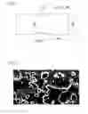

Sources:
- United States Patent and Trademark Office - verify current appl. status at the USPTO↗
Recent applications in this class:
- » 20250171870 2025-05-29
HIGH-Ni ALLOY THICK STEEL PLATE HAVING EXCELLENT WELD HIGH-TEMPERATURE CRACKING RESISTANCE, AND METHOD FOR PRODUCING SAME - » 20250171869 2025-05-29
STEEL SHEET, MEMBER, METHODS FOR MANUFACTURING THE SAME, METHOD FOR MANUFACTURING HOT-ROLLED STEEL SHEET FOR COLD-ROLLED STEEL SHEET, AND METHOD FOR MANUFACTURING COLD-ROLLED STEEL SHEET - » 20250171868 2025-05-29
HOT-ROLLED STEEL SHEET - » 20250163533 2025-05-22
NON-ORIENTED ELECTRICAL STEEL SHEET AND MANUFACTURING METHOD THEREFOR - » 20250163532 2025-05-22
NON-ORIENTED ELECTRICAL STEEL SHEET AND METHOD FOR MANUFACTURING SAME - » 20250163531 2025-05-22
STEEL SHEET, MEMBER, METHODS FOR MANUFACTURING THE SAME, METHOD FOR MANUFACTURING HOT-ROLLED STEEL SHEET FOR COLD-ROLLED STEEL SHEET, AND METHOD FOR MANUFACTURING COLD-ROLLED STEEL SHEET - » 20250163530 2025-05-22
STEEL SHEET, MEMBER, AND METHODS FOR MANUFACTURING THEM - » 20250163529 2025-05-22
METHOD FOR PRODUCING GRAIN-ORIENTED ELECTRICAL STEEL SHEET - » 20250154620 2025-05-15
STEEL PLATE FOR PRESSURE VESSEL WITH EXCELLENT CRYOGENIC TOUGHNESS AND EXCELLENT DUCTILITY AND MANUFACTURING METHOD THEREOF - » 20250154619 2025-05-15
NON-ORIENTED ELECTRIC STEEL SHEET AND MANUFACTURING METHOD THEREFOR
Recent applications for this Assignee:
- » 20210370370 2021-12-02
Method for producing H-shaped steel - » 20210285078 2021-09-16
Shaft part - » 20210285068 2021-09-16
HOT ROLLED STEEL AND STEEL COMPONENT - » 20210231240 2021-07-29
Threaded connection - » 20210202836 2021-07-01
Microswitch and electronic device in which same is used - » 20200376534 2020-12-03
Hot-stamping formed article, vehicle member, and manufacturing method of hot-stamping formed article - » 20200370159 2020-11-26
Steel material for CVT sheave, CVT sheave, and method for manufacturing CVT sheave - » 20200370142 2020-11-26
DRAWN STEEL WIRE - » 20200354810 2020-11-12
HIGH-STRENGTH STEEL WIRE - » 20200307159 2020-10-01
STEEL SHEET FOR CONTAINER