Method and apparatus for surge prevention control of multistage compressor having one surge valve and at least one flow measuring device
US20170082113A1
2017-03-23
15/279,084
2016-09-28
✅ Patent granted
US 10,254,719 B2
2019-04-09
-
-
Tuan A Vu
McKee, Voorhees & Sease, PLC
2037-05-27
Abstract:
A method and apparatus for surge prevention control for multistage compressors with at least two stages, at least one flow measuring device, and one overall surge recycle valve is disclosed. Furthermore, a method of accurate calculation of surge limit line for overall multistage compressor using one available flow measuring device is also disclosed.
The method of surge prevention calculates multistage compressor's surge limit line as a product of individual stages surge limit lines that differs from those revealed in the prior art. This method allows accurate calculation of the distance of operating point to surge limit line that takes in account surge lines of all stages and allows reliable surge prevention control.
Inventors:
- Vadim Shapiro 8 🇺🇸 Clive, IA, United States
- Andriy Nyemchyn 2 🇺🇸 West Des Moines, IA, United States
- Alex Komm 2 🇺🇸 West Des Moines, IA, United States
Assignee:
- Statistics & Control, Inc. 5 🇺🇸 West des Moines, IA, United States
Applicant:
Interested in similar patents?
Get notified when new applications in this technology area are published.
Classification:
F04D27/001 » CPC further
Control, e.g. regulation, of pumps, pumping installations or systems Testing thereof; Determination or simulation of flow characteristics; Stall or surge detection, e.g. condition monitoring
F04D27/02 IPC
Control, e.g. regulation, of pumps, pumping installations or systems Surge control
G05B2219/37371 » CPC further
Program-control systems; Nc systems; Measurements Flow
F04D27/00 IPC
Control, e.g. regulation, of pumps, pumping installations or systems
G05B19/416 » CPC further
Programme-control systems electric; Numerical control [NC], i.e. automatically operating machines, in particular machine tools, e.g. in a manufacturing environment, so as to execute positioning, movement or co-ordinated operations by means of programme data in numerical form characterised by control of velocity, acceleration or deceleration
F04D27/0223 » CPC further
Control, e.g. regulation, of pumps, pumping installations or systems; Surge control by bleeding, bypassing or recycling fluids Control schemes therefor
F02C9/18 » CPC further
Controlling gas-turbine plants; Controlling fuel supply in air- breathing jet-propulsion plants; Control of working fluid flow by bleeding, bypassing or acting on variable working fluid interconnections between turbines or compressors or their stages
F04D17/12 » CPC further
Radial-flow pumps, e.g. centrifugal pumps; Helico-centrifugal pumps; Centrifugal pumps for compressing or evacuating Multi-stage pumps
F05D2240/35 » CPC further
Components Combustors or associated equipment
F05D2270/101 » CPC further
Control; Purpose of the control system to cope with, or avoid, compressor flow instabilities Compressor surge or stall
G05D11/00 IPC
Ratio control
G05B11/42 » CPC main
Automatic controllers electric with provision for obtaining particular characteristics, e.g. proportional, integral, differential for obtaining a characteristic which is both proportional and time-dependent, e.g. P.I., P.I.D.
F04D27/0207 » CPC main
Control, e.g. regulation, of pumps, pumping installations or systems; Surge control by bleeding, bypassing or recycling fluids
Description
CROSS-REFERENCE TO RELATED APPLICATIONS
This application is a continuation-in-part of U.S. Ser. No. 15/267,654, filed Sep. 16, 2016, which claims priority under 35 U.S.C. §119 to provisional application Ser. No. 62/220,642, filed Sep. 18, 2015, both of which are herein incorporated by reference in their entirety.
FIELD OF THE INVENTION
The invention relates generally to a method and apparatus for surge prevention control. More specifically, but not exclusively, the invention relates to a method and apparatus for surge prevention control for multistage compressors with at least two stages, at least one flow measuring device, and one overall surge recycle valve is disclosed. Even more specifically, but not exclusively, the invention relates to a method of accurate calculation of surge limit line for overall multistage compressor using one available flow measuring device.
BACKGROUND OF THE INVENTION
Since a flow-measuring device often is not available between stages, it is difficult to calculate the distance of operating point to surge limit line and perform protective regulatory control action.
BRIEF SUMMARY OF THE INVENTION
Therefore, it is a primary object, feature, and/or advantage of the invention to improve on and/or overcome the deficiencies in the art.
The purpose of this invention is to accurately calculate surge limit line for multistage compressor having one available flow-measuring device. The method is applicable with many types of multistage centrifugal turbo compressors with variable speed, or constant speed and throttle valve for process control.
These and/or other objects, features, and advantages of the invention will be apparent to those skilled in the art. The invention is not to be limited to or by these objects, features and advantages. Obviously many variations of the present invention are possible. Within the scope of present claim the invention can be accomplished otherwise then specifically described below. No single embodiment need provide each and every object, feature, or advantage.
BRIEF DESCRIPTION OF THE DRAWINGS
FIG. 1 shows a surge prevention algorithm for multistage compressor having one available flow-measuring device and one recycle valve.
FIG. 2 shows a general turbo compressor with variable speed drive and sensors arrangements.
FIG. 3 shows a typical compressor map with coordinates provided in terms of polytrophic head versus suction volumetric flow.
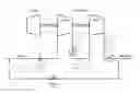
FIG. 4 shows a general multistage turbo compressor with one available flow-measuring device in the suction of first stage and one overall recycle valve.
Various embodiments of the invention will be described in detail with reference to the drawings, wherein like reference numerals represent like parts throughout the several views. Reference to various embodiments does not limit the scope of the invention. Figures represented herein are not limitations to the various embodiments according to the invention and are presented for exemplary illustration of the invention.
DETAILED DESCRIPTION
The invention is directed towards a method and apparatus for surge prevention control. More specifically, but not exclusively, the invention relates to a method and apparatus for surge prevention control for multistage compressors with at least two stages, at least one flow measuring device, and one overall surge recycle valve is disclosed. Even more specifically, but not exclusively, the invention relates to a method of accurate calculation of surge limit line for overall multistage compressor using one available flow measuring device.
The FIG. 3 is typical compressor map. It shows the location of compressor operating point, marked by a blue dot symbol, in reference to various constraints, represented by the limiting lines and performance curves. The performance of centrifugal compressors is best presented in a map showing polytrophic head as a function of the actual inlet flow, with the compressor speed (or inlet guide vanes position) as a parameter. The compressor map contains the following number of constructed lines which are based on manufacturer supplied data and controller real time data:
-
- Performance curves represent possible combinations of flow and pressure for a given speed of rotation and vane setting. FIG. 3 shows performance curves for three different speeds (N_Min, N_c and N_Max).
- The surge line dividing a stable operating region from surge region. To protect a compressor from surge it must be known at what point this event occurs. The surge limit line is built on information received from the compressor manufacturer specification, or surge test data. This line represents actual points at which the compressor surges.
The compressor polytrophic head can be computed from the suction and discharge pressure and temperature and process gas composition. An operating point on a specific curve can be computed via well-known equations below:
H p = ( R c σ - 1 ) σ ⋆ R 0 ⋆ T s ⋆ Z a Mol W 4 - 1
Where
-
- Hp is the polytrophic head in the compressor discharge
- Rc is the compression ratio
- σ is the gas polytrophic exponent
- Ts is the gas suction temperature
- Za is the average gas compressibility factor
- MolW is the gas molecular weight
- R0 is the universal gas constant.
With the polytrophic exponent:
And
σ = n - 1 n = k - 1 k ⋆ η 4 - 2
where
-
- n is the gas polytrophic volume exponent
- η is the compressor efficiency
- k Is isentropic exponent
It is well known that the relationship between the temperature and the compression ratio for the polytrophic processes can be presented with the following formula:
T d T s = ( P d P s ) σ 4 - 3
Therefore, the polytrophic exponent G can be calculated as follows where
-
- Td is the gas discharge temperature
σ = log ( T d T s ) log ( P d P s ) 4 - 4
The actual flow can be calculated via the following equation:
And
Q s = A dP ⋆ T s ⋆ Z s P s ⋆ Mol W 4 - 5
where
-
- kq is a constant coefficient, or
- A is a flow measuring device constant coefficient
- Qs is volumetric flow in the compressor suction
- Zs is the compressor suction gas compressibility factor
- dP is the pressure differential across the flow measuring device in the compressor suction
And density
ρ = Mol W ⋆ P s R 0 ⋆ T s ⋆ Z 4 - 6
The compression ratio Rc is computed as follows:
R c = P d P s 4 - 7
where
-
- Pd is the gas pressure in the compressor discharge
- Ps is the gas pressure in the compressor suction
The FIG. 2 shows a typical Surge Prevention Control System of single stage compressor, which comprises compressor's measurable variables. Surge prevention algorithm uses measurable variables and determines distance to surge that is invariant to changing process conditions. This distance between the compressors's operating point and the surge line is a function of the compression ratio, differential pressure across flow measurement device, the rotational speed (the guide vane angle) and the gas pressure, temperature, and composition. Surge Prevention Control Algorithm uses the surge test data (or manufacturer specified data) recorded for a certain compressor rotational speed/guide vanes position ksu surge coefficient is computed as:
k su = H psu Q ssu 2 4 - 8
where
-
- Hpsu is surge polytrophic head in the compressor discharge
- Qssu is surge volumetric flow in the compressor suction
Or using the equations above:
k su = ( R csu σ - 1 ) σ * P ssu dP ssu 4 - 9
where
-
- Rcsu is surge pressure ratio
- Pssu is surge test suction pressure
- dPsu is surge test pressure differential across the flow measuring device in the compressor suction
The surge control line Set Point (SPsu) defines the desired minimum distance between the operating point and surge limit line. The SPsu is always to the right of the surge line. The surge control margin is the distance between those lines. The Control Line Set Point (SPsu) is calculated by multiplying the Surge Line dPssu value by the Control Line Multiplier (CLM).
SP su = dP ssu * CLM = ( R c σ - 1 ) σ * Ps k su * CLM 4 - 10
where
-
- Rc is current pressure ratio
- Ps is current suction pressure
- dPsu is current surge line pressure differential across the flow measuring device in the compressor suction
The SPC PID process variable is current pressure differential across the flow measuring device (dP). The SPC PID response increases the recycle rate when the operating point is to the left of SPsu by opening of surge control valve and reduces recycle rate when that point is to the right of SPsu by closing of surge control valve.
Strictly speaking, Surge Prevention Control algorithm of single stage compressor is not part of the disclosed invention as a claim, however, its overview is provided for completeness purposes only.
FIG. 4 shows a general multistage turbo compressor with one available flow-measuring device in the suction of first stage and one overall recycle valve. The standard approach consists of the following steps:
-
- 1. Each stage of a compressor is equipped with its own PID surge prevention controller even if there is only one recycle path and control valve for the entire machine.
- 2. If the flow measuring device is not located in suction, of compressor stage then the equation 5-11 is needed to convert flow to suction condition. The equation is used to calculate virtual flow measurements for stages with no flow measuring devices. It is derived from mass and energy balances and calculates differential pressure across each stage virtual flow measuring device (dPv) as function of differential pressure across available flow measured device and ratios of surge conditions pressures, temperatures, and compressibility at the point of available flow measurement and point of virtual flow measuring device location.
dP v = P * T v * Z v P v * T * Z dP 4 - 11
-
- 3. Each stage is equipped with Surge Prevention Controller described on FIG. 2. PID algorithm of Surge Prevention Controller calculates control response. This response represents the intended recycle flow.
- 4. All PID controllers submit their control responses to the valve-sharing selector.
- 5. The response of a valve-sharing algorithm is used to manipulate the recycle valve. The selector protects the entire compressor from surge by selecting the highest of several PID algorithm responses of individual Surge Prevention Controllers.
Implementation
The standard approach overcomplicates control system setup, and reduce systems reliability. The advantage of the present invention over the standard approach is it does not require complex configuration of individual companion Surge Prevention Controller and uses only one controller to protect entire machine. A disclosed method focuses on reliable Surge Prevention control of entire multistage compressor while simplifying the control system configuration and minimizing interaction between control modules.
The overall algorithm is described in FIG. 1. This control diagram illustrates the strategy of multistage Surge Prevention Controller. Proposed method consists of the following steps:
-
- 1. Record surge data based on compressor manufacturer's information, or surge test data. It includes values of each stage measured variables—pressure suction, pressure discharge, temperature suction, temperature discharge, speed (FIGS. 1: 1 and 3), and flow measuring device variables—differential pressure, pressure, temperature (FIG. 1: 2).
- 2. Determining a surge limit line set point of each compressor stage (ksuv) as a function of surge conditions reduced polytrophic head
( R c σ - 1 σ )
and reduce volumetric flow rate
( dP v P )
(FIGS. 1- 4 and 5):
k suv = 1 dP ssu * P v 2 * T ssu * Z ssu P ssu * T v * Z v * R csu * - 1 σ 6 - 12
where
-
- Rcsu is compressor pressure ratio at surge conditions
- Pssu is surge test pressure at flow measuring device
- dPssu is surge test pressure differential across the flow measuring device
- Tssu is surge test temperature at flow measuring device
- Zssu
is surge test compressibility at flow measuring device
-
- Pv is surge test pressure in the compressor stage suction
- Tv is surge test temperature in the compressor stage suction
- Zv is surge test compressibility in the compressor stage suction
- 3. Sensing Stage 1 and Stage 2 variables—pressure suction, pressure discharge, temperature suction, temperature discharge, and speed (FIGS. 1: 6 and 8).
- 4. Sensing flow measuring device variables—differential pressure, pressure, temperature (FIG. 1: 7).
- 5. Calculate each stage current surge limit line pressure differential across the flow measuring device in the compressor suction (FIGS. 1: 9 and 10):
dP ssui = 1 k suv * P v 2 * T * Z P * T v * Z v * R ci σ - 1 σ 6 - 13
where
-
- Rci is compressor stage pressure ratio at current conditions
- P is pressure at flow measuring device at current conditions
- T is temperature at flow measuring device at current conditions
- Z is compressibility at flow measuring device at current conditions
- Pv is pressure in the compressor stage suction at current conditions
- Tv is temperature in the compressor stage suction at current conditions
- Zv is compressibility in the compressor stage suction at current conditions
- 6. Computing overall compressor surge limit set point for current operating conditions by selecting maximal value of all computed individual stages surge limit set points (FIG. 1: 11):
dPssu=MAX (dPssu) 6-14
-
- 7. The Control Line Set Point (SPsu) is calculated by multiplying the Surge Line dPssu value by the Control Line Multiplier (CLM):
SPsu=dPssu*CLM 6-15
Comparing current measured dP with computed overall compressor surge limit set point SPsu and modulating surge control valve. PID algorithm of Surge Prevention Controller calculates control response. This response represents the intended recycle flow (FIG. 1: 12).
Claims
What is claimed is:1. A method for surge prevention control for multistage compressors with at least two stages, at least one flow measuring device, and one surge valve, said method comprising:
Determining a surge limit line set point of each compressor stage (ksuv) as a function of surge conditions reduced polytrophic head
( R c σ - 1 σ )
and reduce volumetric flow rate
( dP v P ) :
k suv = 1 dP ssu * P v 2 * T ssu * Z ssu P ssu * T v * Z v * R csu * - 1 σ ;
Calculating each stage differential pressure surge limit set point for current operating conditions as a function of ksuv and current measured pressures and temperatures:
dP ssui = 1 k suv * P v 2 * T * Z P * T v * Z v * R ci σ - 1 σ ;
Computing overall compressor surge limit set point for current operating conditions by selecting maximal value of all computed individual stages surge limit set points:
dPsp=MAX(dPsp) ;
Calculating the Control Line Set Point (SPsu) by multiplying the Surge Line dPssu value by the Control Line Multiplier (CLM):
SPsu=dPssu*CLM
2. The method of claim 1, wherein for a variable speed compressor the drive surge limit set points of each stage are determined as a function of speed (N).
3. The method of claim 1, further comprising comparing current measured dP with computed overall compressor surge limit set point SPsu and modulating surge control valve based on comparison for compressor surge prevention.
4. A method of accurate calculation of surge limit line for overall multistage compressor using one available flow measuring device, one speed signal, pressure and temperature signals of suction and discharge of each stage, said method comprising:
Determining a surge limit line set point of each compressor stage (ksuv) as a function of surge conditions reduced polytrophic head
( R c σ - 1 σ )
and reduce volumetric flow rate
( dP v P ) :
k suv = 1 dP ssu * P v 2 * T ssu * Z ssu P ssu * T v * Z v * R csu * - 1 σ ;
Calculating each stage differential pressure surge limit set point for current operating conditions as a function of ksuv and current measured pressures and temperatures:
dP ssui = 1 k suv * P v 2 * T * Z P * T v * Z v * R ci σ - 1 σ
Computing overall compressor surge limit set point for current operating conditions by selecting maximal value of all computed individual stages surge limit set points:
dPsp=MAX(dPspi); and
Calculating the Control Line Set Point (SPsu) by multiplying the Surge Line dPssu value by the Control Line Multiplier (CLM):
SPsu=dPssu*CLM
5. The method of claim 4, wherein for a variable speed compressor drive surge limit set points of each stage are also determined as a function of speed (N).
6. The method of claim 4, further comprising Comparing current measured dP with computed overall compressor surge limit set point SPsu and modulating surge control valve based on comparison for compressor surge prevention.
7. An apparatus for surge prevention control, said apparatus comprising:
a multistage compressor comprising:
a) with at least two stages;
b) at least one flow measuring device; and
c) a surge valve.
Images & Drawings included:


Sources:
- United States Patent and Trademark Office - verify current appl. status at the USPTO↗
Recent applications in this class:
- » 20230025097 2023-01-26
Centrifugal compressor with recirculation passage - » 20220010802 2022-01-13
Centrifugal compressor with recirculation passage - » 20220010801 2022-01-13
Turbo blower capable of operating in surge area - » 20210285457 2021-09-16
SURGING PRECURSOR DETECTING DEVICE, METHOD OF DETECTING SURGING PRECURSOR, AND PROGRAM - » 20210190084 2021-06-24
Method for controlling the outlet pressure of a compressor - » 20210115936 2021-04-22
Shroud with continuous slot and angled bridges - » 20200208642 2020-07-02
Unloading device for HVAC compressor with mixed and radial compression stages - » 20190301478 2019-10-03
COMPRESSOR ANTI-SURGE PROTECTOIN UNDER WET GAS CONDITIONS - » 20190301477 2019-10-03
Adaptive anti surge control system and method - » 20190249681 2019-08-15
Centrifugal compressor with recirculation passage
Recent applications for this Assignee:
- » 20170085086 2017-03-23
Method and apparatus for voltage control in electric power systems - » 20140260249 2014-09-18
Method and apparatus for improving electro-hydraulic and electro-mechanical integrated control systems of a steam turbine - » 20130317629 2013-11-28
Method of large scale process optimization and optimal planning based on real time dynamic simulation - » 15144898 2018-10-30
Method and apparatus for voltage control in electric power systems