Fitting for coupling to a pipe
US20170082226A1
2017-03-23
15/311,451
2015-05-21
✅ Patent granted
US 10,655,765 B2
2020-05-19
WO; PCT/EP2015/061204; 20150521
WO; WO2015/177259; 20151126
Anna M Momper | Fannie C Kee
Harness, Dickey & Pierce, P.L.C.
2035-05-21
Abstract:
A fitting for coupling to at least one pipe, comprising:
-
- a sleeve for receiving the pipe;
- at least one sealing member to provide a seal between the sleeve and the pipe;
- a pressure member for applying a pressure to the sleeve and to the pipe;
- gripper teeth provided on the pressure member and arranged to act on the pipe; and
- actuation means for exerting a pressure to the pressure member comprising a pressure ring acting on the pressure member through adjoining slanting contacting surfaces of said pressure ring and pressure member, respectively;
- wherein the at least one sealing member is positioned between the pressure member and the pipe;
wherein the at least one sealing member is connected with or pressed against the sleeve without being positioned between the pressure member and the sleeve.
Inventors:
- Michel Paul HULSEBOS 2 🇳🇱 Holten, Netherlands
- Jeroen WIJLENS 1 🇳🇱 Haaksbergen, Netherlands
- Roel Alexander Maria WELLINK 1 🇳🇱 Usselo, Netherlands
Assignee:
- Georg Fischer WAGA N.V. 5 🇳🇱 Epe, Netherlands
Applicant:
Interested in similar patents?
Get notified when new applications in this technology area are published.
Classification:
F16L17/10 » CPC further
Joints with packing adapted to sealing by fluid pressure the packing being sealed by the pressure of a fluid other than the fluid in or surrounding the pipe
F16L19/065 » CPC further
Joints in which sealing surfaces are pressed together by means of a member, e.g. a swivel nut, screwed on or into one of the joint parts in which radial clamping is obtained by wedging action on non-deformed pipe ends the wedging action being effected by means of a ring
F16L37/62 » CPC further
Couplings of the quick-acting type pneumatically or hydraulically actuated
F16L21/007 » CPC further
Joints with sleeve or socket clamped by a wedging action
F16L21/04 » CPC further
Joints with sleeve or socket with elastic sealing rings between pipe and sleeve or between pipe and socket, e.g. with rolling or other prefabricated profiled rings in which sealing rings are compressed by axially-movable members
F16L21/08 » CPC main
Joints with sleeve or socket with additional locking means
F16L21/00 IPC
Joints with sleeve or socket
Description
CROSS-REFERENCE TO RELATED APPLICATIONS
This application is a 371 National Stage of International Application No. PCT/EP2015/061204, filed on May 21, 2015, and published in English as WO 2015/177259 A1 on Nov. 26, 2015. This application claims priority to Netherlands Application No. 2012869, filed on May 22, 2014 and Netherlands Application No. 2013241, filed on Jul. 23, 2014. The entire disclosures of the above applications are incorporated herein by reference.
FIELD
The disclosure relates to a fitting for coupling to at least one pipe.
BACKGROUND
This section provides background information related to the present disclosure which is not necessarily prior art.
EP-A-0 794 378 discloses a fitting for coupling to at least one pipe, comprising:
-
- a sleeve for receiving the pipe;
- at least one sealing member to provide a seal between the sleeve and the pipe;
- a pressure member for applying a pressure to the sleeve and to the pipe;
- gripper teeth provided on the pressure member and arranged to act on the pipe; and
- actuation means for exerting a pressure to the pressure member comprising a pressure ring acting on the pressure member through adjoining slanting contacting surfaces of said pressure ring and pressure member respectively.
In the fitting of EP-A-0 794 378 the sealing member is arranged between the pressure member and the pipe and between the pressure member and the sleeve in order to provide the required seal between the sleeve and the pipe.
A fitting according to the preamble of the main claim is further known from WO2011/120669.
During installation of the fitting the actuation means of the fitting are arranged so as to have the pressure member apply a pressure capable to withstand for a stand time of not less than 50 years axial forces that may act on the pipe which is received in the sleeve; to provide sufficient pressure both on the part of the sealing member positioned between the pressure member and the pipe and on the part of the sealing member positioned between the pressure member and the sleeve; and to compensate for relaxation of the material of the fitting that may occur during said fifty-year stand time. The pressures that are thus applied to the sealing member, in particular on the part of the sealing member between the pressure member and the sleeve are at such a high level that the sealing member, usually rubber, is overstressed in particular when the pipe diameter is larger than 300 mm. It is particularly with diameters larger than 300 mm that the required pretension on the part of the sealing member between the pressure member and the sleeve becomes too high for the rubber of the sealing member to survive and maintain its long-term physical properties.
SUMMARY
This section provides a general summary of the disclosure, and is not a comprehensive disclosure of its full scope or all of its features.
It is therefore an object of the disclosure to provide a solution to this problem, and to provide a fitting having a lifetime of at least 50 years, and which can withstand axial forces that may come to work on the pipe during this lifetime whilst maintaining its sealing properties, and which can cope with the general deterioration of the fitting during its lifetime, also when the fitting is dimensioned for pipes having a diameter larger than 300 mm.
The fitting of the disclosure first and foremost is arranged with the feature that the at least one sealing member is connected with or pressed against the sleeve without being positioned between the pressure member and the sleeve. This arranges for a completely closed seal between the sleeve and the pipe wherein the sealing property of the fitting of the disclosure is not linked to the pressure applied by the pressure member. Accordingly the level of the pressure applied by the pressure member has no bearing anymore on the lifetime of the sealing between the pressure member and the sleeve.
In a suitable embodiment opposite extremities of the at least one sealing member are connected to the pressure member and the sleeve respectively.
In a further suitable embodiment the at least one sealing member is connected with or pressed against the sleeve without being positioned between the slanting surfaces of the pressure ring and the pressure member. This contributes to the longevity of the fitting of the disclosure.
In a particular embodiment it is desirable that the fitting comprises a clip for attaching the sealing member to the sleeve. This makes mounting and dismounting of the fitting very easy without sacrificing reliability.
Further areas of applicability will become apparent from the description provided herein. The description and specific examples in this summary are intended for purposes of illustration only and are not intended to limit the scope of the present disclosure.
DRAWINGS
The drawings described herein are for illustrative purposes only of selected embodiments and not all possible implementations, and are not intended to limit the scope of the present disclosure.
The disclosure will hereinafter be further elucidated with reference to the drawing.
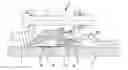
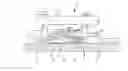
In the drawing of a single FIGURE a preferred embodiment is shown of the fitting of the disclosure.
The FIGURE shows an embodiment of the fitting 1 of the disclosure for application with a pipe 2. The fitting has a sleeve 10 for receiving the pipe 2, at least one sealing member 4 to provide a seal between the sleeve 10 and the pipe 2, a pressure member 5 for applying a pressure to the sleeve 10 and to the pipe 2, gripper teeth 6 provided on the pressure member 5 and arranged to act on the pipe 2, and actuation means 3, 7 that are tuneable from a single point outside the sleeve 10 for arranging that a pressure is applied to the pressure member 5.
The actuation means 3, 7 comprise a pressure ring 3 acting on the pressure member 5 through adjoining slanting contacting surfaces 11′, 11″ of said pressure ring 3 and pressure member 5, respectively. This arranges that a force applied to the pressure member 5 in parallel with a longitudinal body axis of the sleeve 10 or the pipe 2, acts on the pressure member 5 with a component perpendicular to said longitudinal body axis of the sleeve 10 on the pipe 2 received in said sleeve 10.
The sealing member 4 is in accordance with the disclosure positioned between the pressure member 5 and the pipe 2 and is connected with or pressed against the sleeve 10 without being positioned between the pressure member 5 and the sleeve 10.
One of the further characterizing features of the fitting 1 of the disclosure is that it is provided with said sealing member 4 without same being positioned between the slanting surface 11′ of the pressure ring 3 and the slanting surface 11″ of the pressure member 5.
Furthermore it is preferable that opposite extremities of the at least one sealing member 4 are connected to the pressure member 5 and to the sleeve 10 respectively.
DETAILED DESCRIPTION
Example embodiments will now be described more fully with reference to the accompanying drawings.
The FIGURE further shows that the fitting 1 of the disclosure is preferably further provided with a clip 13 for attaching the sealing member 4 to the sleeve 10. This makes mounting and dismounting of the fitting very easy without sacrificing reliability.
Although the disclosure has been discussed in the foregoing with reference to a variety of embodiments of the fitting of the disclosure, the disclosure is not restricted to these particular embodiments which can be varied further in many ways without departing from the disclosure. The discussed exemplary embodiments shall therefore not be used to construe the appended claims strictly in accordance therewith. On the contrary the embodiments are merely intended to explain the wording of the appended claims without intent to limit the claims to the discussed exemplary embodiments. The scope of protection of the disclosure shall therefore be construed in accordance with the appended claims only, wherein a possible ambiguity in the wording of the claims shall be resolved using these exemplary embodiments.
The foregoing description of the embodiments has been provided for purposes of illustration and description. It is not intended to be exhaustive or to limit the disclosure. Individual elements or features of a particular embodiment are generally not limited to that particular embodiment, but, where applicable, are interchangeable and can be used in a selected embodiment, even if not specifically shown or described. The same may also be varied in many ways. Such variations are not to be regarded as a departure from the disclosure, and all such modifications are intended to be included within the scope of the disclosure.
Claims
1. A fitting for coupling to at least one pipe, comprising:
a sleeve for receiving the pipe;
at least one sealing member to provide a seal between the sleeve and the pipe;
a pressure member for applying a pressure to the sleeve and to the pipe;
gripper teeth provided on the pressure member and arranged to act on the pipe; and
actuation means for exerting a pressure to the pressure member comprising a pressure ring acting on the pressure member through adjoining slanting contacting surfaces of said pressure ring and pressure member, respectively;
wherein the at least one sealing member is positioned between the pressure member and the pipe;
wherein
the at least one sealing member is connected with or pressed against the sleeve without being positioned between the pressure member and the sleeve.
2. The fitting according to claim 1, wherein the opposite extremities of the at least one sealing member are connected to the pressure member and the sleeve respectively.
3. The fitting according to claim 1, wherein the at least one sealing member is connected with, or pressed against, the sleeve without being positioned between the slanting surfaces of the pressure ring and the pressure member.
4. The fitting according to claim 1, further comprising a clip for attaching the sealing member to the sleeve.
5. The fitting according to claim 2, wherein the at least one sealing member is connected with, or pressed against, the sleeve without being positioned between the slanting surfaces of the pressure ring and the pressure member.
6. The fitting according to claim 2, further comprising a clip for attaching the sealing member to the sleeve.
7. The fitting according to claim 3, further comprising a clip for attaching the sealing member to the sleeve.
Images & Drawings included:
Sources:
- United States Patent and Trademark Office - verify current appl. status at the USPTO↗
Similar patent applications:
- » 13134805
Quick coupling pipe fitting system - » 20150323112
Push-Fit Pipe Couplings - » 20180202586
Pipe coupling fitting with internal spacer sleeve - » 20080277610
PUSH FIT COUPLING AND PIPE CONNECTION FOR A PUSH FIT COUPLING - » 20090200797
PIPE FITTING AND PIPE COUPLING ASSEMBLY EMPLOYING SUCH FITTING - » 20180141249
Coupling fitting for pipes - » 20090260216
Device and method for coupling a pipe fitting to a pipe - » 20090315325
Female quick coupling fitting element for pipes - » 20190032825
Pre-assembled coupling assemblies with pipe fitting - » 20190063645
Pre-assembled coupling assemblies with pipe fitting
Recent applications in this class:
- » 20250216009 2025-07-03
Mechanical Joint Retainer Gland - » 20250084937 2025-03-13
PIPE JOINT AND PIPE JOINING METHOD - » 20250052346 2025-02-13
Pipe Connector for Tightly Connecting Two Pipe Ends, Use Thereof and Method - » 20250027587 2025-01-23
Mechanical joint retainer gland - » 20250020248 2025-01-16
UNIVERSAL TUBE STUB PLUG WITH SEAL PORT - » 20250012387 2025-01-09
GARDEN FLUID FLOW CONNECTORS - » 20240418304 2024-12-19
MEDIUM CONNECTOR - » 20240401728 2024-12-05
GASKET ASSEMBLY - » 20240401727 2024-12-05
TWO-PHASE CONNECTOR - » 20240353036 2024-10-24
RING MEMBER
Recent applications for this Assignee:
- » 20200139465 2020-05-07
COUPLING DEVICE - » 20120061956 2012-03-15
Coupling device - » 20110148105 2011-06-23
Coupling device and method for manufacturing a grip ring to be used in such a coupling device - » 20080303223 2008-12-11
Coupling device for a tube