Powder removal
US20170113253A1
2017-04-27
14/924,046
2015-10-27
✅ Patent granted
US 10,220,422 B2
2019-03-05
-
-
William McCalister
Locke Lord LLP | Daniel J. Fiorello | Scott D. Wofsy
2036-12-16
Abstract:
A method includes issuing a state change fluid into an internal passage of an additively manufactured article and causing the state change fluid to change from a first state having a first viscosity to a second state that is either solid or has a second viscosity that is higher than the first viscosity within the internal passage. The method can also include causing the state change fluid to change back from the second state to the first state and flushing the state change fluid from the internal passage to remove residual powder from the additively manufactured article.
Inventors:
- Sergey Mironets 95 🇺🇸 Charlotte, NC, United States
- Eric Karlen 45 🇺🇸 Rockford, IL, United States
- Colette O. Fennessy 5 🇺🇸 Bloomfield, CT, United States
- Kiley J. Versluys 9 🇺🇸 Hartford, CT, United States
- Diana Giulietti 16 🇺🇸 Tariffville, CT, United States
Assignee:
- HAMILTON SUNDSTRAND CORPORATION 2,631 🇺🇸 Charlotte, NC, United States
Applicant:
Interested in similar patents?
Get notified when new applications in this technology area are published.
Classification:
B08B3/04 » CPC further
Cleaning by methods involving the use or presence of liquid or steam Cleaning involving contact with liquid
B08B3/10 » CPC further
Cleaning by methods involving the use or presence of liquid or steam; Cleaning involving contact with liquid with additional treatment of the liquid or of the object being cleaned, e.g. by heat, by electricity, by vibration
B08B9/00 » CPC further
Cleaning hollow articles by methods or apparatus specially adapted thereto
B29C64/35 » CPC further
Additive manufacturing, i.e. manufacturing of three-dimensional [3D] objects by additive deposition, additive agglomeration or additive layering, e.g. by 3D printing, stereolithography or selective laser sintering; Auxiliary operations or equipment Cleaning
B65G47/252 » CPC further
Article or material-handling devices associated with conveyors; Methods employing such devices; Devices influencing the relative position or the attitude of articles during transit by conveyors orientating the articles by turning over or inverting them about an axis substantially perpendicular to the conveying direction
B65G57/035 » CPC further
Stacking of articles by adding to the top of the stack from above with a stepwise downward movement of the stack
B65G57/10 » CPC further
Stacking of articles by adding to the top of the stack from alongside by devices, e.g. reciprocating, acting directly on articles for horizontal transport to the top of stack
B65G57/245 » CPC further
Stacking of articles by adding to the top of the stack; Stacking of articles of particular shape three-dimensional, e.g. cubiform, cylindrical in layers each of predetermined arrangement the layers being transferred as a whole, e.g. on pallets with a stepwise downward movement of the stack
F15D1/00 » CPC further
Influencing flow of fluids
B08B2209/005 » CPC further
Details of machines or methods for cleaning hollow articles Use of ultrasonics or cavitation, e.g. as primary or secondary action
B22F5/10 » CPC further
Manufacture of workpieces or articles from metallic powder characterised by the special shape of the product of articles with cavities or holes, not otherwise provided for in the preceding subgroups
B22F2003/247 » CPC further
Manufacture of workpieces or articles from metallic powder characterised by the manner of compacting or sintering; Apparatus specially adapted therefor ; Presses and furnaces; After-treatment of workpieces or articles Removing material: carving, cleaning, grinding, hobbing, honing, lapping, polishing, milling, shaving, skiving, turning the surface
B22F2999/00 » CPC further
Aspects linked to processes or compositions used in powder metallurgy
B33Y40/00 » CPC further
Auxiliary operations or equipment, e.g. for material handling
B65G2203/0283 » CPC further
Indexing code relating to control or detection of the articles or the load carriers during conveying; Control or detection relating to the load carrier(s) Position of the load carrier
B65G2203/0291 » CPC further
Indexing code relating to control or detection of the articles or the load carriers during conveying; Control or detection relating to the load carrier(s) Speed of the load carrier
B08B3/12 » CPC main
Cleaning by methods involving the use or presence of liquid or steam; Cleaning involving contact with liquid with additional treatment of the liquid or of the object being cleaned, e.g. by heat, by electricity, by vibration by sonic or ultrasonic vibrations
B65G57/03 IPC
Stacking of articles by adding to the top of the stack from above
B65G57/24 IPC
Stacking of articles by adding to the top of the stack; Stacking of articles of particular shape three-dimensional, e.g. cubiform, cylindrical in layers each of predetermined arrangement the layers being transferred as a whole, e.g. on pallets
B22F3/105 IPC
Manufacture of workpieces or articles from metallic powder characterised by the manner of compacting or sintering; Apparatus specially adapted therefor ; Presses and furnaces; Sintering only by using electric current , laser radiation or plasma
B22F3/24 IPC
Manufacture of workpieces or articles from metallic powder characterised by the manner of compacting or sintering; Apparatus specially adapted therefor ; Presses and furnaces After-treatment of workpieces or articles
Description
BACKGROUND
1. Field
The present disclosure relates to additive manufacturing methods and systems, more specifically to methods and systems for powder removal for additively manufactured articles.
2. Description of Related Art
Certain methods for additive manufacturing using powder beds (e.g., selective laser sintering) cause powder to be left within internal passages of the additively manufactured article. Traditional methods for removing of such remaining powder can damage internal passages, lead to material weakness in the additively manufactured part, and/or leave excessive amounts of residual powder within the internal passages. The ability to effectively remove powder from certain types and/or sizes of internal features is a limiting design factor for AM articles.
Such conventional methods and systems have generally been considered satisfactory for their intended purpose. However, there is still a need in the art for improved powder removal for additively manufactured articles. The present disclosure provides a solution for this need.
SUMMARY
A method includes issuing a state change fluid into an internal passage of an additively manufactured article and causing the state change fluid to change from a first state having a first viscosity to a second state that is either solid or has a second viscosity that is higher than the first viscosity within the internal passage. The method can also include causing the state change fluid to change back from the second state to the first state and flushing the state change fluid from the internal passage to remove residual powder from the additively manufactured article.
The method can include applying vibration, such as ultrasonic vibration, to the additively manufactured article while the state change fluid is in the second state. Causing the state change fluid to change from the first state to the second state can include applying heat to the state change fluid. For example, the state change fluid can include poly(N-isopropylacrylamide) or any other suitable thermal-responsive polymer that becomes more viscous or solidifies with added heat.
Causing the state change fluid to change from the first state to the second state can include cooling the state change fluid. For example, the state change fluid can include an ionic liquid that is crystalline at room temperature and melts to freely flow above room temperature. In certain embodiments, the ionic liquid can include [bmim]NTf2. In such embodiments, the method can further include heating the ionic liquid to change the ionic liquid from the second state to the first state before inputting the ionic liquid into the internal passage.
Causing the state change fluid to change from the first state to the second state can include applying a pressure or force to the state change fluid. For example, the state change fluid can include a non-Newtonian fluid that becomes more viscous or rigid with applied kinetic energy.
Inputting the state change fluid can include applying a pressure to the state change fluid. Causing the state change fluid to change from the first state to the second state can include removing the applied pressure or reducing pressure to the state change fluid. For example, the state change fluid can include a non-Newtonian fluid that flows more freely with higher pressure (e.g., a clay suspension).
In accordance with at least one aspect of this disclosure, an additively manufactured article includes an internal passage, the internal passages being cleared of residual powder by any suitable portion or combination of portions of a method as described above.
These and other features of the systems and methods of the subject disclosure will become more readily apparent to those skilled in the art from the following detailed description taken in conjunction with the drawings.
BRIEF DESCRIPTION OF THE DRAWINGS
So that those skilled in the art to which the subject disclosure appertains will readily understand how to make and use the devices and methods of the subject disclosure without undue experimentation, embodiments thereof will be described in detail herein below with reference to certain figures, wherein:
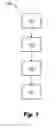
FIG. 1 is a flowchart of an embodiment of a method in accordance with this disclosure;
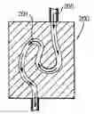
FIG. 2 is a cross-sectional elevation view of an embodiment of an additively manufactured article having an internal flow passage, showing a state change fluid flowing therethrough in a first state;
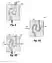
FIG. 3A is a cross-sectional elevation view of an the additively manufactured article of FIG. 2, showing the state change fluid converted to a substantially solid form in an embodiment of a second state in accordance with this disclosure; and
FIG. 3B is a cross-sectional elevation view of an the additively manufactured article of FIG. 2, showing the state change fluid converted to a more viscous state in another embodiment of a second state in accordance with this disclosure.
DETAILED DESCRIPTION
Reference will now be made to the drawings wherein like reference numerals identify similar structural features or aspects of the subject disclosure. For purposes of explanation and illustration, and not limitation, an illustrative view of an embodiment of a method in accordance with the disclosure is shown in FIG. 1 and is designated generally by reference character 100. Other embodiments and/or aspects of this disclosure are shown in FIGS. 2-3B. The systems and methods described herein can be used to remove residual powder from within internal passages of additively manufactured articles, for example.
Referring to FIGS. 1 and 2-3B, a method 100 includes inputting (e.g., at block 101) a state change fluid 205 into an internal passage 201 of an additively manufactured article 200. The method 100 also includes causing (e.g., at block 103) the state change fluid 205 to change from a first state having a first viscosity (e.g., as shown in FIG. 2) to a second state that is either solid (e.g., as shown FIG. 3A) or has a second viscosity that is higher than the first viscosity (e.g., as shown in FIG. 3B) while the state change fluid 205 is within the internal passage 201.
The method 100 can also include causing (e.g., at block 105) the state change fluid 205 to change back from the second state (e.g., FIG. 3A and/or FIG. 3B) to the first state (e.g., FIG. 2). After converting back to the first state, the method 100 can include flushing (e.g., at block 107) the state change 205 fluid from the internal passage 201 to remove residual powder from the additively manufactured article 200.
Referring to FIGS. 3A and 3B, the method 100 can include applying vibration 307 to the additively manufactured article 200 while the state change fluid 205 is in the second state. In certain embodiments, the vibration can be ultrasonic vibration. Any other suitable mode of vibration is contemplated herein and any type of transducer for vibration can be used to vibrate the additively manufactured article 200 and/or the state change fluid 205 within the internal passage 201.
In certain embodiments, causing the state change fluid 205 to change from the first state to the second state can include applying heat to the state change fluid 205. For example, the state change 205 fluid can include poly(N-isopropylacrylamide) or any other suitable thermal-responsive polymer that becomes more viscous and/or solidifies with added heat.
Causing the state change fluid to change 205 from the first state to the second state can include cooling the state change fluid 205. For example, the state change fluid 205 can include an ionic liquid that is crystalline at room temperature and melts to freely flow above room temperature. In certain embodiments, the ionic liquid can include [bmim]NTf2. In such embodiments, the method 100 can further include heating the ionic liquid to change the ionic liquid from the second state to the first state before inputting the ionic liquid into the internal passage 201.
In certain embodiments, causing the state change fluid 205 to change from the first state to the second state includes applying a pressure or force to the state change fluid 205. For example, the state change fluid 205 can include a non-Newtonian fluid that becomes more viscous and/or rigid with applied kinetic energy (e.g., cornstarch in water).
In certain embodiments, inputting the state change fluid 205 includes applying a pressure to the state change fluid 205. Causing the state change fluid 205 to change from the first state to the second state can include removing the applied pressure or reducing pressure to the state change fluid 205. For example, the state change fluid 205 can include a non-Newtonian fluid that flows more freely with higher pressure (e.g., a clay suspension).
In accordance with at least one aspect of this disclosure, an additively manufactured article 200 includes an internal passage 201, the internal passage 201 being cleared of residual powder by any suitable portion or combination of portions of a method 100 as described above.
Embodiments as described above allow for more effective powder removal than traditional methods and systems. Increasing the viscosity of a flushing fluid (e.g., the state change fluid 205) can allow the flushing to be more effective. For example, vibrating the article 200 after changing to a more viscous or solid state translates the vibration energy to powder particles that are stuck inside the internal passage. This increase as energy translation improves particle separation from the internal passage, thereby cleaning out the internal passage better without the need for corrosive or abrasive solutions which can comprise the integrity of the article 200. This also allows for additive manufacturing design freedom not previously attainable with traditional techniques.
The methods and of the present disclosure, as described above and shown in the drawings, provide for additively manufactured articles with superior properties including improved residual powder removal from internal passages therein. While the apparatus and methods of the subject disclosure have been shown and described with reference to embodiments, those skilled in the art will readily appreciate that changes and/or modifications may be made thereto without departing from the spirit and scope of the subject disclosure.
Claims
What is claimed is:1. A method, comprising:
issuing a state change fluid into an internal passage of an additively manufactured article; and
causing the state change fluid to change from a first state having a first viscosity to a second state that is either solid or has a second viscosity that is higher than the first viscosity within the internal passage.
2. The method of claim 1, further comprising applying vibration to the additively manufactured article while the state change fluid is in the second state.
3. The method of claim 2, wherein the vibration is ultrasonic vibration.
4. The method of claim 1, wherein causing the state change fluid to change from the first state to the second state includes applying heat to the state change fluid.
5. The method of claim 4, wherein the state change fluid includes poly(N-isopropylacrylamide).
6. The method of claim 1, wherein causing the state change fluid to change from the first state to the second state includes cooling the state change fluid.
7. The method of claim 6, wherein the state change fluid includes an ionic liquid that is crystalline at room temperature and melts to freely flow above room temperature.
8. The method of claim 7, wherein the ionic liquid includes [bmim]NTf2.
9. The method of claim 7, further comprising heating the ionic liquid to change the ionic liquid from the second state to the first state before inputting the ionic liquid into the internal passage.
10. The method of claim 1, wherein causing the state change fluid to change from the first state to the second state includes applying a pressure or force to the state change fluid.
11. The method of claim 1, wherein issuing the state change fluid includes applying a pressure to the state change fluid.
12. The method of claim 11, wherein causing the state change fluid to change from the first state to the second state includes removing an applied pressure or reducing pressure to the state change fluid.
13. The method of claim 12, wherein the state change fluid includes a non-Newtonian fluid that flows more freely with higher pressure.
14. The method of claim 13, wherein the state change fluid includes a clay suspension.
15. The method of claim 1, further comprising:
causing the state change fluid to change back from the second state to the first state; and
flushing the state change fluid from the internal passage to remove residual powder from the additively manufactured article.
16. An additively manufactured article having an internal passage, wherein the internal passage is cleared of residual powder by a method, the method comprising:
issuing a state change fluid into an internal passage of an additively manufactured article;
causing the state change fluid to change from a first state having a first viscosity to a second state that is either solid or has a second viscosity that is higher than the first viscosity within the internal passage;
causing the state change fluid to change back from the second state to the first state; and
flushing the state change fluid from the internal passage to remove residual powder from the additively manufactured article.
Images & Drawings included:
Sources:
- United States Patent and Trademark Office - verify current appl. status at the USPTO↗
Similar patent applications:
- » 20200276622
POWDER REMOVING APPARATUS AND POWDER REMOVING SYSTEM - » 20230103709
Powder removal assemblies and methods of removing unbound particles using powder removal assemblies - » 20250178090
POWDER REMOVAL ASSEMBLIES AND METHODS OF REMOVING UNBOUND PARTICLES USING POWDER REMOVAL ASSEMBLIES - » 20240253125
ELECTROSTATIC POWDER REMOVER FOR POWDER BED FUSION ADDITIVE MANUFACTURING - » 20240390981
POWDER REMOVAL SYSTEM FOR POWDER BASED MANUFACTURING METHODS - » 20220063198
Post-build quick powder removal system for powder bed fusion additive manufacturing - » 20230332285
Powder conveying apparatus, gas supply apparatus, and method for removing powder - » 20110044859
Synthesis reaction system for hydrocarbon compound, and method of removing powdered catalyst particles - » 18152854
Method and apparatus for powder removal in an additive manufacturing system - » 20120324828
Powder removal device of medicine dispenser
Recent applications in this class:
- » 20250256308 2025-08-14
SUBSTRATE CLEANING METHOD AND SUBSTRATE CLEANING APPARATUS - » 20250242390 2025-07-31
PORTABLE ULTRASONIC CLEANING SYSTEM FOR SMALL ITEMS - » 20250229301 2025-07-17
Golf Club Cleaning Device - » 20250196199 2025-06-19
ELECTRONIC COMPONENT CLEANING METHOD - » 20250108411 2025-04-03
SUBSTRATE TREATMENT APPARATUS AND PROCESSING METHOD OF SUBSTRATE - » 20240416393 2024-12-19
APPARATUS FOR CLEANING INDUSTRIAL COMPONENTS - » 20240293850 2024-09-05
METHOD FOR REMOVING LAYERS OF SILICON CARBIDE, AS WELL AS PROCESS AND APPARATUS FOR CLEANING EPITAXIAL REACTOR COMPONENTS - » 20240286174 2024-08-29
WORKPIECE CLEANING METHOD AND CLEANING DEVICE - » 20240278292 2024-08-22
ULTRASONIC SHOWER CLEANING DEVICE - » 20240269716 2024-08-15
Ultrasonic cleaning method
Recent applications for this Assignee:
- » 20250260037 2025-08-14
SYSTEMS AND METHODS FOR ALANE-BASED POWER GENERATION - » 20250250000 2025-08-07
HYDRAULIC DRAG BRAKE - » 20250230772 2025-07-17
MULTI TEMPERATURE GENERATOR AND ENGINE SHARED OIL - » 20250227854 2025-07-10
COVERLAY AS PRINTED CIRCUIT BOARD (PCB) VOLTAGE INSULATOR UNDER CONNECTORS - » 20250226734 2025-07-10
COMPOSITE ROTORS AND METHODS OF MAKING COMPOSITE ROTORS - » 20250224141 2025-07-10
THERMOELECTRIC VORTEX TUBES - » 20250218620 2025-07-03
ISOLATION BARRIER SYSTEMS - » 20250217200 2025-07-03
DECENTRALIZED SCHEDULER OF COMPUTATION JOBS FOR UNSTABLE NETWORK OF HETEROGENOUS NODES - » 20250196039 2025-06-19
FILTER ASSEMBLY - » 20250189500 2025-06-12
AEROSOL DETECTION SYSTEMS