Wheel rim generator
US20170117774A1
2017-04-27
15/297,403
2016-10-19
✅ Patent granted
US 10,763,726 B2
2020-09-01
-
-
Alexander Talpalatski
2038-06-09
Abstract:
A wheel rim generator is provided, including: a wheel rim having a rim, a disc, and an axis of rotation; a bearing having an outer race and an inner race, said inner race is disposed around said rim within the rim width; a rotor configured to rotate with said outer race, has at least one permanent magnet, and a center of gravity being displaced from said axis of rotation; and a stator configured to rotate with said rim, form at least one magnetic circuit with said rotor, and generate electromotive force with one of constant and changing magnetic flux in said at least one magnetic circuit as said wheel rim rotates.
Applicant:
Interested in similar patents?
Get notified when new applications in this technology area are published.
Classification:
B60C23/00 IPC
Devices for measuring, signalling, controlling, or distributing tyre pressure or temperature, specially adapted for mounting on vehicles; Arrangement of tyre inflating devices on vehicles, e.g. of pumps or of tanks; Tyre cooling arrangements
B60C23/06 IPC
Devices for measuring, signalling, controlling, or distributing tyre pressure or temperature, specially adapted for mounting on vehicles; Arrangement of tyre inflating devices on vehicles, e.g. of pumps or of tanks; Tyre cooling arrangements Signalling devices actuated by deformation of the tyre, e.g. tyre mounted deformation sensors or indirect determination of tyre deformation based on wheel speed, wheel-centre to ground distance or inclination of wheel axle
B60C23/041 » CPC further
Devices for measuring, signalling, controlling, or distributing tyre pressure or temperature, specially adapted for mounting on vehicles; Arrangement of tyre inflating devices on vehicles, e.g. of pumps or of tanks; Tyre cooling arrangements; Signalling devices actuated by tyre pressure mounted on the wheel or tyre transmitting the signals by non-mechanical means from the wheel or tyre to a vehicle body mounted receiver Means for supplying power to the signal- transmitting means on the wheel
B60C23/0488 » CPC further
Devices for measuring, signalling, controlling, or distributing tyre pressure or temperature, specially adapted for mounting on vehicles; Arrangement of tyre inflating devices on vehicles, e.g. of pumps or of tanks; Tyre cooling arrangements; Signalling devices actuated by tyre pressure mounted on the wheel or tyre comprising additional sensors in the wheel or tyre mounted monitoring device, e.g. movement sensors, microphones or earth magnetic field sensors Movement sensor, e.g. for sensing angular speed, acceleration or centripetal force
B60C23/064 » CPC further
Devices for measuring, signalling, controlling, or distributing tyre pressure or temperature, specially adapted for mounting on vehicles; Arrangement of tyre inflating devices on vehicles, e.g. of pumps or of tanks; Tyre cooling arrangements; Signalling devices actuated by deformation of the tyre, e.g. tyre mounted deformation sensors or indirect determination of tyre deformation based on wheel speed, wheel-centre to ground distance or inclination of wheel axle comprising tyre mounted deformation sensors, e.g. to determine road contact area
H02K7/08 » CPC further
Arrangements for handling mechanical energy structurally associated with dynamo-electric machines, e.g. structural association with mechanical driving motors or auxiliary dynamo-electric machines Structural association with bearings
H02K11/0094 » CPC further
Structural association of dynamo-electric machines with electric components or with devices for shielding, monitoring or protection Structural association with other electrical or electronic devices
H02K11/33 » CPC further
Structural association of dynamo-electric machines with electric components or with devices for shielding, monitoring or protection; Structural association with control circuits or drive circuits Drive circuits, e.g. power electronics
B60C23/002 » CPC further
Devices for measuring, signalling, controlling, or distributing tyre pressure or temperature, specially adapted for mounting on vehicles; Arrangement of tyre inflating devices on vehicles, e.g. of pumps or of tanks; Tyre cooling arrangements; Devices for manually or automatically controlling or distributing tyre pressure whilst the vehicle is moving by monitoring conditions other than tyre pressure or deformation
H02K7/18 IPC
Arrangements for handling mechanical energy structurally associated with dynamo-electric machines, e.g. structural association with mechanical driving motors or auxiliary dynamo-electric machines Structural association of electric generators with mechanical driving motors, e.g. with turbines
B60C23/04 IPC
Devices for measuring, signalling, controlling, or distributing tyre pressure or temperature, specially adapted for mounting on vehicles; Arrangement of tyre inflating devices on vehicles, e.g. of pumps or of tanks; Tyre cooling arrangements; Signalling devices actuated by tyre pressure mounted on the wheel or tyre
H02K11/20 » CPC further
Structural association of dynamo-electric machines with electric components or with devices for shielding, monitoring or protection for measuring, monitoring, testing, protecting or switching
B60B21/12 » CPC further
Rims Appurtenances, e.g. lining bands
B60C29/02 » CPC further
Arrangements of tyre-inflating valves to tyres or rims; Accessories for tyre-inflating valves, not otherwise provided for Connection to rims
H02K11/00 IPC
Structural association of dynamo-electric machines with electric components or with devices for shielding, monitoring or protection
H02K7/1846 » CPC main
Arrangements for handling mechanical energy structurally associated with dynamo-electric machines, e.g. structural association with mechanical driving motors or auxiliary dynamo-electric machines; Structural association of electric generators with mechanical driving motors, e.g. with turbines; Rotary generators structurally associated with wheels or associated parts
B60C23/0498 » CPC further
Devices for measuring, signalling, controlling, or distributing tyre pressure or temperature, specially adapted for mounting on vehicles; Arrangement of tyre inflating devices on vehicles, e.g. of pumps or of tanks; Tyre cooling arrangements; Signalling devices actuated by tyre pressure mounted on the wheel or tyre; Constructional details of means for attaching the control device for rim attachments
B60B2900/351 » CPC further
Purpose of invention; Increase in versatility, e.g. usable for different purposes or different arrangements
B60C19/00 IPC
Tyre parts or constructions not otherwise provided for
B60R16/04 » CPC further
Electric or fluid circuits specially adapted for vehicles and not otherwise provided for; Arrangement of elements of electric or fluid circuits specially adapted for vehicles and not otherwise provided for electric constitutive elements Arrangement of batteries
H02K7/1876 » CPC further
Arrangements for handling mechanical energy structurally associated with dynamo-electric machines, e.g. structural association with mechanical driving motors or auxiliary dynamo-electric machines; Structural association of electric generators with mechanical driving motors, e.g. with turbines; Linear generators; sectional generators with reciprocating, linearly oscillating or vibrating parts
B60R16/033 » CPC further
Electric or fluid circuits specially adapted for vehicles and not otherwise provided for; Arrangement of elements of electric or fluid circuits specially adapted for vehicles and not otherwise provided for electric constitutive elements for supply of electrical power to vehicle subsystems or for characterised by the use of electrical cells or batteries
B60C2019/004 » CPC further
Tyre parts or constructions not otherwise provided for Tyre sensors other than for detecting tyre pressure
B60C23/10 » CPC further
Devices for measuring, signalling, controlling, or distributing tyre pressure or temperature, specially adapted for mounting on vehicles; Arrangement of tyre inflating devices on vehicles, e.g. of pumps or of tanks; Tyre cooling arrangements Arrangement of tyre-inflating pumps mounted on vehicles
Description
BACKGROUND OF THE INVENTION
1. Field of the Invention
The present invention relates generally to the field of electric generators, more specifically to the wheel rim generators powered by the mechanical energy of a rotating vehicle wheel.
2. Description of the Prior Art
U.S. Pat. No. 4,229,728 discloses an electric generator externally mounted on the wheel axles of a vehicle, which has a rotor center of gravity being displaced from the axis of wheel rotation, so that the rotor always seeks the lowest vertical position, and the motive force for power generation in a rolling environment is naturally provided by gravity.
U.S. Pat. No. 7,126,233 discloses another non-center engagement generator which is implemented within a rotating reference frame, in particular the need for an access to the axis of rotation is eliminated.
Both above patents make use of changing magnetic flux in generator's magnetic circuits to induce electromotive force, consequently an undesirable fluctuating torque caused by attracting and repelling magnetic forces is inevitable, no matter the generator is standing by or turned off.
A smoother running, higher output-power yet robust wheel rim generator is certainly the ultimate goal of all related art, but there seems to exist an air of mystery that has not been fully unveiled, the present invention is therefore such an attempt trying to fulfill the necessity.
SUMMARY OF THE INVENTION
An object of the present invention is to provide an independent electrical power source for each vehicle wheel, so that autonomous tire pressure regulation in each wheel is achievable. Whenever a footprint sensor for the loaded tire is also available, individual footprint area of every pneumatic tire can be further optimized regardless of uneven load distribution of the vehicle.
To achieve the above and other objects, a wheel rim generator is provided, including: a wheel rim having a rim, a disc, and an axis of rotation; a bearing having an outer race and an inner race, said inner race is disposed around said rim within the rim width; a rotor configured to rotate with said outer race, has at least one permanent magnet, and a center of gravity being displaced from said axis of rotation; and a stator configured to rotate with said rim, form at least one magnetic circuit with said rotor, and generate electromotive force with one of constant and changing magnetic flux in said at least one magnetic circuit as said wheel rim rotates.
The followings explain the present invention in detail, the embodiments are explanatory of the present invention and the drawings are illustrative only.
BRIEF DESCRIPTION OF THE DRAWINGS
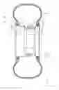
FIG. 1 is a preferred embodiment of the present invention;
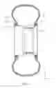
FIG. 2 is illustrative of the displaced CG for the rotor of said preferred embodiment;
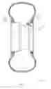
FIG. 3 is the first variant of said preferred embodiment;
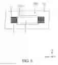
FIG. 4 is the second variant of said preferred embodiment;
FIG. 5 is a sectional view of a wheel rim fitted with said second variant; and
FIG. 6 is a sectional view of said second variant.
DETAILED DESCRIPTION OF THE PREFERRED EMBODIMENTS
The present invention is a wheel rim generator, comprises a wheel rim, a bearing, a rotor, and a stator.
Said wheel rim 9 has a rim, a disc, and an axis of rotation. Said bearing has an outer race and an inner race, said inner race is disposed around said rim within the rim width. Said rotor is configured to rotate with said outer race, has at least one permanent magnet, and a center of gravity being displaced from said axis of rotation. Said stator is configured to rotate with said rim, form at least one magnetic circuit with said rotor, and generate electromotive force with one of constant and changing magnetic flux in said at least one magnetic circuit as said wheel rim rotates.
FIGS. 1 through 2 represent a preferred embodiment of the present invention. An electric generator 100 is disposed around a tire-sitting rim 91, has a ring-shaped stator 1, a ring-shaped rotor 2, and two ball bearings 3. In said preferred embodiment, said rim is represented by said tire-sitting rim 91, said rim has a flat well base portion 95 being extended to one rim flange 94 of said rim, said bearing is represented by two said ball bearing 3, said rotor is represented by said ring-shaped rotor 2, said stator is represented by said ring-shaped stator 1. Said two ball bearings 3, said ring-shaped rotor 2 and said ring-shaped stator 1 may be sealed in a vacuum space.
Said ring-shaped stator 1 is disposed around said tire-sitting rim 91, rotates with said tire-sitting rim 91 about an axis of rotation L, and comprises a conductor winding 11.
Said ring-shaped rotor 2 rotates freely around said tire-sitting rim 91 about L by the support of two said ball bearing 3, two said ball bearing 3 are also disposed around said tire-sitting rim 91. Said ring-shaped rotor 2 has a center of gravity C being displaced from L, and comprises a magnetic part 21 that can be a permanent magnet, generates electromotive force in said conductor winding 11 whenever said tire-sitting rim 91 rotates.
The shortest distance between L and C is 0, the gravity pulling at C is G; define the direction of a line pointing from L to C having a distance D to be α, and define the angle between α and G to be Θ. Therefore the power generating torque is given by G.D.Sine(Θ), said power generating torque has a maximum of G.D when Θ equals +90° or −90°.
FIG. 3 is the first variant of said preferred embodiment. Said ring-shaped stator 1 of an electric generator 200 is disposed around an inner race 31′ of a ball bearing 3′, said inner race 31′ is in turn disposed around said tire-sitting rim 91. Said ring-shaped rotor 2 of said electric generator 200 is configured to rotate with an outer race 32′ of said ball bearing 3′, a number of rolling balls 33′ interface between said inner race 31′ and said outer race 32′. A control circuitry 51 is connected to said ring-shaped stator 1 and is attached to said inner race 31′, controls Θ to be within +90° and −90° by regulating output current of said conductor winding 11, depending on the direction of advance of said tire-sitting rim 91. Said control circuitry 51 may coordinate a power factor correction unit 58 and a power converter 59 in the control of Θ, the same principle is also applicable to said preferred embodiment.
It is preferable for said electric generator 200 to further comprise a control and processing unit 56, at least one battery 53, both air pressure and air temperature sensors 54, an inflation and deflation system 52, an accelerometer 55, a tire footprint sensor 57, said power factor correction unit 58, and said power converter 59, which are all functionally coupled to said ring-shaped stator 1.
Said control and processing unit 56 has hardware and software combined capabilities of computation, is also built in a storage memory and a wireless transmitter 60. Said inflation and deflation system 52 speaks for the value of a second air valve.
Said tire footprint sensor 57 projects a light beam on a point of tire internal surface perpendicularly from said tire-sitting rim 91, detects rapid and significant changes in the reflection of said light beam due to tire deflection as said point travels across said tire footprint. By analyzing a signal corresponding to said reflection in the opposite direction of said light beam, said tire footprint is characterized by two instants when said point touches and leaves said tire footprint, in addition to the cyclic period of rotation of said tire-sitting rim 91. Hence the central angle of said tire footprint is revealed, leading to the footprint area and further to tire load with a knowledge of tire pressure.
FIGS. 4 through 6 represent the second variant of said preferred embodiment, the present invention is expanded from rotational motion to linear motion of gravity-drived power generation, and is scaled down to be implemented in an air valve. Said rim has at least two valve stem holes 96. An electric generator 300 having a valve stem 8 (such as air valve) is fitted to said tire-sitting rim 91, has both a stator 1′ and a rotor 2′. Said rotor 2′ is configured to form a magnetic circuit with said stator 1′, and slide freely between two limit positions of said stator V. Said stator 1′ has a conductor winding and generates electromotive force in said conductor winding, when said rotor 2′ reciprocates by gravity as said tire-sitting rim 91 rotates.
Engineering and theoretical concerns of the present invention are explained in more details in the following.
First, since air drag acting on said rotor inside a tire builds up exponentially with driving speed, therefore it is preferable for said bearing, said rotor, and said stator to be concealed in vacuum at the well base (drop center) portion of said rim, by a dedicated sealing rim covering said well base. Secondly, in order to dispose said bearing, said stator as well as said sealing rim around said rim, said well base portion should be extended to one rim flange of said rim, and said rim flange should be detachable either by screw threads or bolts.
To generate electromotive force according to Faraday's law with constant magnetic flux in a magnetic circuit, move perpendicularly a conductor wire of length l at velocity υthrough a magnetic field of flux density B, the potential difference at the two ends of said conductor wire is given by emf=l.υ.B. This implies the air gap in the magnetic circuit of FIG. 3 remains consistent, so as the cross section of said ring-shaped stator 1, thus thinner gauge wire windings taking up the least air gap in said magnetic circuit of FIG. 3 would be the best solution to the end.
The control of Θ has to take bearing friction into account. The frictional torque of a bearing is given by Tbearing=Kbearing.(Kvisc.N)(2/3), where Kbearing is a bearing specific constant, Kvisc is the viscosity of bearing lubricant, and N is the rotational speed of the bearing in rpm. Let
Kbearing.(Kvisc.Nmax)(2/3)=0.1G.D for a highly efficient design with the maximum rotational speed rating being Nmax, so Kvisc=((0.1G.D/Kbearing)/Nmax(2/3))(3/2). By adjusting Kvisc and/or the multiplication of G and D to satisfy the last equation, the maximum net torque available for power generation remains equal or greater than 0.9 G.D for all N by design.
Further denote ω for the angular speed and Eff for the efficiency of the generator, and suppose Tbearing can be ignored in a practical design. According to the law of energy conservation, mechanical input and electrical output power of the generator is established: Vout,rms.Iout,rms=ω.G.D.Sine(Θ).Eff. Thus, Θ=Inverse Sine(Iour,rms.(Vout,rms/ω)/(G.D.Eff)). Because Vout,rms/ω Eff are nearly constant around an operating point, hence Θ is mainly controlled by generator output current regardless of the vehicle speed.
But still vehicle deceleration caused by hard braking poses a critical concern, the forward moving inertia of C must be dealt with care in such a situation. One simple solution is to introduce an additional term into the control equation of Θ to counter react or minimize the undesirable effect, which is proportional to and in the opposite sign of the time-rate of change of ω.
Although particular embodiments of the invention have been described in detail for purposes of illustration, various modifications and enhancements may be made without departing from the spirit and scope of the invention. Accordingly, the invention is not to be limited except as by the appended claims.
Claims
What is claimed is:1. A wheel rim generator, including:
a wheel rim having a rim, a disc, and an axis of rotation;
a bearing having an outer race and an inner race, said inner race is disposed around said rim within the rim width;
a rotor configured to rotate with said outer race, has at least one permanent magnet, and a center of gravity being displaced from said axis of rotation; and
a stator configured to rotate with said rim, form at least one magnetic circuit with said rotor, and generate electromotive force with one of constant and changing magnetic flux in said at least one magnetic circuit as said wheel rim rotates.
2. The wheel rim generator of claim 1, wherein said bearing, said rotor, and said stator are sealed in a vacuum space.
3. The wheel rim generator of claim 1, wherein said bearing is a ceramic ball bearing.
4. The wheel rim generator of claim 1, wherein said rim has a flat well base portion being extended to one rim flange of said rim.
5. The wheel rim generator of claim 4, wherein said rim flange is detachable.
6. The wheel rim generator of claim 1, wherein said rim has at least two valve stem holes.
7. The wheel rim generator of claim 1, further including at least one battery, an inflation and deflation system, both air pressure and air temperature sensors, an accelerometer, a tire footprint sensor, a wireless transmitter, a power factor correction unit, a power converter, and a control and processing unit.
Images & Drawings included:


Sources:
- United States Patent and Trademark Office - verify current appl. status at the USPTO↗
Similar patent applications:
Recent applications in this class:
- » 20250233482 2025-07-17
POWER GENERATING WHEEL RIM DEVICE - » 20250158485 2025-05-15
IN-WHEEL ELECTRIC GENERATOR APPARATUS - » 20240364184 2024-10-31
CONSTANT MICRO POWER ENERGY SYSTEM (CMPES) DEVICE - » 20240322647 2024-09-26
VEHICLE ENERGY GENERATION SYSTEM - » 20240283326 2024-08-22
SYSTEMS AND METHODS FOR POWER GENERATION, TRANSMISSION, AMPLIFICATION AND/OR STORAGE - » 20240171042 2024-05-23
SYSTEM AND METHOD FOR SUPPLYING ELECTRICAL POWER VIA AN AXLE - » 20240063690 2024-02-22
ADVANCED KINETIC ENERGY RECOVERY SYSTEM (AKERS) FOR ELECTRIC AIRCRAFT - » 20240048029 2024-02-08
CIRCUIT BOARD AND POWER SUPPLY DEVICE - » 20240014708 2024-01-11
IN-WHEEL GENERATOR - » 20240006960 2024-01-04
Electric Automobile that runs without using any other power except a battery pack and never has to be plugged in to recharge; engineering allows it to recharge itself while in movement