Inner static electricity eliminating control valve for organic solvent delivery pipelines
US20170127503A1
2017-05-04
15/204,334
2016-07-07
✅ Patent granted
US 10,129,967 B2
2018-11-13
-
-
Charles Freay
Egbert Law Offices, PLLC
2037-04-04
Abstract:
An inner static electricity eliminating control valve for organic solvent delivery pipelines is disclosed. The inner static electricity eliminating control valve is to be installed on and connected to an organic solvent delivery pipeline, to eliminate the inner static electricity generated by the organic solvent inside the organic solvent delivery pipeline. The inner static electricity eliminating control valve includes a valve casing, a main valve chamber, a pneumatic valve, a subsidiary valve chamber, a check valve, a static electricity export mechanism and a solvent export portion, wherein, the pneumatic valve can periodically apply pressure toward the organic solvent inside the main valve chamber, so that the organic solvent inside the main valve chamber can be delivered periodically through the check valve to the subsidiary valve chamber, and during this process, the static electricity export mechanism will export and eliminate the static electricity existing in the organic solvent.
Inventors:
- Chien-Kuo LU 1 🇹🇼 Taipei, Taiwan
- Hui-Hua TIEN 1 🇹🇼 Taipei, Taiwan
- Chi-Yuan PUNG 1 🇹🇼 Taipei, Taiwan
Assignee:
- MARKETECH INTERNATIONAL CORP. 22 🇹🇼 Taipei, Taiwan
Applicant:
Interested in similar patents?
Get notified when new applications in this technology area are published.
Classification:
F16K15/02 IPC
Check valves with guided rigid valve members
F16K15/026 » CPC further
Check valves with guided rigid valve members the valve being loaded by a spring the valve member being a movable body around which the medium flows when the valve is open
H05F3/02 » CPC main
Carrying-off electrostatic charges by means of earthing connections
H05F3/02 » CPC main
Carrying-off electrostatic charges by means of earthing connections
F16K31/12 » CPC further
Operating means Actuating devices; ; Releasing devices actuated by fluid
F04B9/1276 » CPC further
Piston machines or pumps characterised by the driving or driven means to or from their working members the means being fluid the fluid being elastic, e.g. steam or air having only one pumping chamber rectilinear movement of the pumping member in the working direction being obtained by a single-acting elastic-fluid motor, e.g. actuated in the other direction by gravity or a spring with fluid-actuated inlet or outlet valve
F04B7/02 » CPC further
Piston machines or pumps characterised by having positively-driven valving the valving being fluid-actuated
F04B19/22 » CPC further
Machines or pumps having pertinent characteristics not provided for in, or of interest apart from, groups - ; Other positive-displacement pumps of reciprocating-piston type
F04B49/00 » CPC further
Control, e.g. of pump delivery, or pump pressure of, or safety measures for, machines, pumps, or pumping installations, not otherwise provided for, or of interest apart from, groups -
F04B49/10 » CPC further
Control, e.g. of pump delivery, or pump pressure of, or safety measures for, machines, pumps, or pumping installations, not otherwise provided for, or of interest apart from, groups - Other safety measures
F04B53/10 » CPC further
Component parts, details or accessories not provided for in, or of interest apart from, groups - or - Valves; Arrangement of valves
F16K51/00 » CPC further
Other details not peculiar to particular types of valves or cut-off apparatus
H05F3/025 » CPC further
Carrying-off electrostatic charges by means of earthing connections Floors or floor coverings specially adapted for discharging static charges
H05F3/025 » CPC further
Carrying-off electrostatic charges by means of earthing connections Floors or floor coverings specially adapted for discharging static charges
F04B15/00 » CPC further
Pumps adapted to handle specific fluids, e.g. by selection of specific materials for pumps or pump parts
F04B9/127 » CPC further
Piston machines or pumps characterised by the driving or driven means to or from their working members the means being fluid the fluid being elastic, e.g. steam or air having only one pumping chamber rectilinear movement of the pumping member in the working direction being obtained by a single-acting elastic-fluid motor, e.g. actuated in the other direction by gravity or a spring
F04B19/04 » CPC further
Machines or pumps having pertinent characteristics not provided for in, or of interest apart from, groups - Pumps for special use
Description
CROSS-REFERENCE TO RELATED U.S. APPLICATIONS
Not applicable.
STATEMENT REGARDING FEDERALLY SPONSORED RESEARCH OR DEVELOPMENT
Not applicable.
NAMES OF PARTIES TO A JOINT RESEARCH AGREEMENT
Not applicable.
REFERENCE TO AN APPENDIX SUBMITTED ON COMPACT DISC
Not applicable.
BACKGROUND OF THE INVENTION
1. Field of the Invention
The present invention relates generally to a static electricity eliminating structure, and more particularly to an innovative structural design of an inner static electricity eliminating control valve for organic solvent delivery pipelines.
2. Description of Related Art Including Information Disclosed Under 37 CFR 1.97 and 37 CFR 1.98
At present, the central chemical supply systems and equipment used by most technical manufacturers are facing risks and dangers because, when supplying high-resistance, inflammable, and explosive chemicals, a large amount of static electricity will be generated due to friction during the flow of organic solvent inside the delivery pipeline. When such static electricity is accumulated to a certain high intensity, there might be risks and dangers of breakdown, spark, ignition or explosion.
If the above-mentioned solvent delivery pipeline is made of stainless steel pipes, the metal material itself will conduct the triboelectricity generated during the flow of liquid. However, there are many different kinds of organic solvent liquids to be delivered by the pipelines, and some special liquids may develop chemical actions with the stainless steel material of the pipeline and cause qualitative change. Hence, some manufacturers are changing to Teflon pipes. Adoption of this kind of pipes can solve the above problem, but will derive another problem. Because Teflon pipes are not conductors, they can not eliminate the static electricity generated during the delivery of liquid. Hence, the afore-mentioned risks and dangers of breakdown, flashover, spark, ignition or explosion will still happen when the inner static electricity is accumulated.
Thus, to overcome the aforementioned problems of the prior art, it would be an advancement in the art to provide an improved structure that can significantly improve the efficacy.
Therefore, the inventors have provided the present invention of practicability after deliberate design and evaluation based on years of experience in the production, development and design of related products.
BRIEF SUMMARY OF THE INVENTION
The “inner static electricity eliminating control valve for organic solvent delivery pipelines” disclosed in the present invention mainly comprises a valve casing, a main valve chamber, a pneumatic valve, a subsidiary valve chamber, a check valve, a static electricity export mechanism, and a solvent export portion. Based on such an innovative and unique structural design and technical characteristics, the present invention achieves an inventive step upon the existing structures proposed in “prior art”. Based on the present invention, the pneumatic valve can periodically apply a pressure toward the organic solvent inside the main valve chamber, so that the organic solvent inside the main valve chamber can be periodically delivered through the check valve to the subsidiary valve chamber, and during this process, the static electricity export mechanism can export and eliminate the static electricity in the organic solvent. Hence, the present invention has achieved an inventive step to effectively eliminate the inner static electricity inside the organic solvent delivery pipeline.
Although the invention has been explained in relation to its preferred embodiment, it is to be understood that many other possible modifications and variations can be made without departing from the spirit and scope of the invention as hereinafter claimed.
BRIEF DESCRIPTION OF THE SEVERAL VIEWS OF THE DRAWINGS
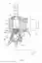
FIG. 1 is a plane view of the embodiment of the present invention of an inner static electricity eliminating control valve installed on the organic solvent delivery pipeline.
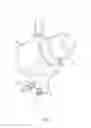
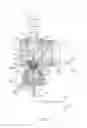
FIG. 2 is an assembled perspective view of a preferred embodiment of the present invention of an inner static electricity eliminating control valve.
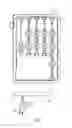
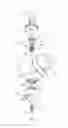
FIG. 3 is an exploded perspective view of a preferred embodiment of the present invention of an inner static electricity eliminating control valve.
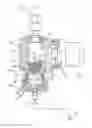
FIG. 4 is an assembled sectional view of a preferred embodiment of the present invention of an inner static electricity eliminating control valve.
FIG. 5 is a working state view of the present invention of an inner static electricity eliminating control valve.
DETAILED DESCRIPTION OF THE INVENTION
FIGS. 1, 2, 3, and 4 are disclosure of a preferred embodiment of the present invention of an inner static electricity eliminating control valve for organic solvent delivery pipelines. However, such preferred embodiment is for descriptive purposes only, and is not intending to limit the scope of patent application. Said inner static electricity eliminating control valve A is to be installed on and connected to an organic solvent delivery pipeline 10 (note: installation is not limited to pipelines inside or outside the manifold), to eliminate the inner static electricity generated by the organic solvent inside the organic solvent delivery pipeline 10.
The inner static electricity eliminating control valve A comprises:
-
- a valve casing 20, including a pipeline connection portion 21, to be installed on and connected to the organic solvent delivery pipeline 10;
- a main valve chamber 30, provided inside the valve casing 20, with one side of the main valve chamber 30 communicated to the pipeline connection portion 21, so that the organic solvent can be introduced into the main valve chamber 30 through the pipeline connection portion 21;
- a pneumatic valve 40, provided on the other side of the main valve chamber 30, said pneumatic valve 40 configured with a pressure applying portion 41 towards the main valve chamber 30, said pressure applying portion 41 can periodically generate pressure towards the organic solvent inside the main valve chamber 30;
- a subsidiary valve chamber 50, provided inside the valve casing 20 and separated from the main valve chamber 30 through a separating wall 51;
- a check valve 60, provided between the main valve chamber 30 and the subsidiary valve chamber 50, and the checking direction of the check valve 60 is set to allow only one-way flow of the organic solvent from the main valve chamber 30 towards the subsidiary valve chamber 50;
- a static electricity export mechanism 70, provided on one side of the subsidiary valve chamber 50, said static electricity export mechanism 70 including a metal static electricity export head 71 configured inside the subsidiary valve chamber 50 and a static electricity conduction wire 72 connected to the metal static electricity export head 71 and extending out of the valve casing 20, the outward extending end of the static electricity conduction wire 72 has a grounding portion 73;
- a solvent export portion 80, provided on one side of the subsidiary valve chamber 50 and located at an interval with the static electricity export mechanism 70, said solvent export portion 80 being provided to release and export excessive organic solvent inside the subsidiary valve chamber 50.
Referring to FIGS. 3 and 4, the metal static electricity export head 71 of the static electricity export mechanism 70 can be designed in a conic shape.
In particular, said metal static electricity export head 71 is preferably made of blunt metal material (for example: gold) for a good static electricity export effect.
Referring to FIGS. 3 and 4, the check valve 60 can include a limiting cover 61, a checking cock body 62 and a coil spring 63;
-
- the position of the main valve chamber 30 for installation of the check valve 60 is provided with an inner thread section 31, and the peripheral of one end of the limiting cover 61 of the check valve 60 is provided with an outer thread section 64, for screw joint with the inner thread section 31, such that this end of the limiting cover 61 pushes tightly against the separating wall 51 provided between the main valve chamber 30 and the subsidiary valve chamber 50;
- the center of the other end of the limiting cover 61 is provided with a through hole 65, communicated to a holding chamber 66 provided inside the limiting cover 61, the end of the holding chamber 66 corresponding to the through hole 65 is provided with a conic ring wall 665, said checking cock body 62 and coil spring 63 being held inside the holding chamber 66 of the limiting cover 61;
- accordingly, the checking cock body 62 has a conic ring rim 625, relatively abutting the conic ring wall 665 provided on the holding chamber 66;
- said coil spring 63 is fitted between the checking cock body 62 and the separating wall 51, elastically pushing the checking cock body 62 towards the conic ring wall 665 provided on the holding chamber 66; furthermore, said separating wall 51 is configured with a passing hole 510, communicated to the holding chamber 66 and subsidiary valve chamber 50 provided inside the limiting cover 61.
Particularly, said checking cock body 62 and coil spring 63 can be an integrally formed structure (such as a plastic injection formed style).
Based on the above-mentioned structural composition and technical features, the working condition of the preferred embodiment of the present invention is described as below: referring to FIG. 5, because, in application, said inner static electricity eliminating control valve A is to be installed on and connected to the organic solvent delivery pipeline 10, the organic solvent 90 flowing inside the organic solvent delivery pipeline 10 can go through the pipeline connection portion 21 and be introduced into the main valve chamber 30, and the pressure applying portion 41 of the pneumatic valve 40 will periodically (for example, every 10 seconds or every 1 minute etc) apply a pressure toward the organic solvent 90 inside main valve chamber 30 (as marked by Arrow L1), under the pressure, the organic solvent 90 inside the main valve chamber 30 will be periodically squeezed and be delivered through the check valve 60 to the subsidiary valve chamber 50 (as marked by Arrow L2). During the above-mentioned delivery of the organic solvent 90, the metal static electricity export head 71 of the static electricity export mechanism 70 provided inside the subsidiary valve chamber 50 will export the static electricity existing in the organic solvent 90 (including static electricity existing in the organic solvent 90 inside the organic solvent delivery pipeline 10, the main valve chamber 30 and the subsidiary valve chamber 50), and through the static electricity conduction wire 72 and grounding portion 73, the static electricity is sent to the outside (as marked by Arrow L3). In this way, the present invention achieves a practical effect of eliminating the inner static electricity inside the organic solvent delivery pipeline 10.
Moreover, when the pressure applying portion 41 of the pneumatic valve 40 stops applying pressure, because the checking cock body 62 inside the check valve 60 will be elastically pushed back by the coil spring 63 to restore the closed state, so that the organic solvent 90 will not lose dramatically, but be emitted periodically in small quantities.
Claims
We claim:1. An inner static electricity eliminating control valve for organic solvent delivery pipelines, said inner static electricity eliminating control valve is to be installed on and connected to an organic solvent delivery pipeline, to eliminate the inner static electricity generated by the organic solvent inside the organic solvent delivery pipeline;
said inner static electricity eliminating control valve comprises:
a valve casing, including a pipeline connection portion, to be installed on and connected to the organic solvent delivery pipeline;
a main valve chamber, provided inside the valve casing, and one side of the main valve chamber is communicated to the pipeline connection portion, so that the organic solvent can go through the pipeline connection portion and be introduced into the main valve chamber;
a pneumatic valve, provided on the other side of the main valve chamber, said pneumatic valve configured with a pressure applying portion towards the main valve chamber, said pressure applying portion can periodically generate pressure towards the organic solvent inside the main valve chamber;
a subsidiary valve chamber, provided inside the valve casing and separated from the main valve chamber through a separating wall;
a check valve, provided between the main valve chamber and the subsidiary valve chamber, and the checking direction of the check valve is set to allow only one-way flow of the organic solvent from the main valve chamber towards the subsidiary valve chamber;
a static electricity export mechanism, provided on one side of the subsidiary valve chamber, said static electricity export mechanism including a metal static electricity export head configured inside the subsidiary valve chamber and a static electricity conduction wire connected to the metal static electricity export head and extending out of the valve casing, the outward extending end of the static electricity conduction wire has a grounding portion;
a solvent export portion, provided on one side of the subsidiary valve chamber and located at an interval with the static electricity export mechanism, said solvent export portion being provided to release and export excessive organic solvent inside the subsidiary valve chamber.
2. The device defined in claim 1, wherein said metal static electricity export head of the static electricity export mechanism is configured in a conic shape.
3. The device defined in claim 2, wherein said metal static electricity export head is preferably made of blunt metal material.
4. The device defined in claim 3, wherein said check valve includes a limiting cover, a checking cock body and a coil spring;
the position of the main valve chamber for installation of the check valve is provided with an inner thread section, and the peripheral of one end of the limiting cover of the check valve is provided with an outer thread section, for screw joint with the inner thread section, such that this end of the limiting cover pushes tightly against the separating wall provided between the main valve chamber and the subsidiary valve chamber;
the center of the other end of the limiting cover is provided with a through hole, communicated to a holding chamber 66 provided inside the limiting cover, the end of the holding chamber corresponding to the through hole is provided with a conic ring wall, said checking cock body and coil spring being held inside the holding chamber of the limiting cover;
accordingly, the checking cock body has a conic ring rim, relatively abutting the conic ring wall provided on the holding chamber;
said coil spring is fitted between the checking cock body and the separating wall, elastically pushing the checking cock body towards the conic ring wall provided on the holding chamber;
furthermore, said separating wall is configured with a passing hole, communicated to the holding chamber and subsidiary valve chamber provided inside the limiting cover.
5. The device defined in claim 4, wherein said checking cock body and coil spring is an integrally formed structure.
Images & Drawings included:
Sources:
- United States Patent and Trademark Office - verify current appl. status at the USPTO↗
Recent applications in this class:
- » 20250247937 2025-07-31
Static Discharge System for Floor-Covering Storage and Dispensing Unit - » 20250220797 2025-07-03
MATERIAL HANDLING CONTAINER WITH ELECTROSTATIC DISCHARGE PROTECTION - » 20250113425 2025-04-03
Electrostatic Grounding Connection - » 20250024576 2025-01-16
GROUNDING DEVICE FOR A LOCAL GAS EXTRACTOR, A LOCAL GAS EXTRACTOR WITH SUCH A GROUNDING DEVICE AND A METHOD FOR MOUNTING SUCH A GROUNDING DEVICE - » 20240389213 2024-11-21
ELECTROSTATIC DISCHARGE PREVENTION PUMP - » 20240276624 2024-08-15
ANKLET FOR EARTH GROUNDING AND ELECTROSTATIC RELEASE - » 20240260163 2024-08-01
VEHICLE STATIC ELIMINATOR AND VEHICLE EQUIPPED WITH THE SAME - » 20240080959 2024-03-07
STATIC ELIMINATOR - » 20230276560 2023-08-31
FRACTURING WELL SITE SYSTEM - » 20230225038 2023-07-13
Systems and methods for monitoring electrostatic buildup for an attraction system
Recent applications for this Assignee:
- » 20210378080 2021-12-02
Active fluid static elimination system - » 20200377358 2020-12-03
Cap rotation device - » 20200377294 2020-12-03
Multifunction cap replacement module - » 20190127206 2019-05-02
Automatic cover-opening and connector-replacing device for chemical container - » 20120248079 2012-10-04
CENTERING STRUCTURE AND METHOD FOR MACHINING OF A SOLAR CELL - » 20120073284 2012-03-29
HOT ZONE HEAT TRANSFER STRUCTURE OF A STIRLING ENGINE - » 20110220624 2011-09-15
METHOD FOR USE OF A DEVICE FOR CUTTING THE PERIPHERAL ISOLATION LINES OF SOLAR PANELS - » 20110090099 2011-04-21
System and method for encoding and decoding serial signals formed by a plurality of color lights - » 20080219551 2008-09-11
Image processing apparatus - » 20080117334 2008-05-22
Gain-determining method and apparatus for grayscale white balance of display apparatus