Method for manufacturing an underlay material, and underlay material
US20170151768A1
2017-06-01
15/432,512
2017-02-14
✅ Patent granted
US 10,357,950 B2
2019-07-23
-
-
Philip C Tucker | Brian R Slawski
Young & Thompson
2037-08-14
Abstract:
A method for manufacturing an underlay material (8) to be set under parquet or a laminate, the underlay material including a sheet material layer (1) and a flexible cellular plastic material layer (3) bonded under the sheet material layer, and a bottom surface of the cellular plastic layer being processed for providing an air space, whereby the bottom surface of the cellular plastic material layer (3) is processed by melting the cellular plastic material locally for providing an air space (9) and for simultaneously bonding the cellular plastic material layer to the sheet material layer (1). An underlay material manufactured by such a method is also described.
Applicant:
Interested in similar patents?
Get notified when new applications in this technology area are published.
Classification:
B32B38/06 » CPC further
Ancillary operations in connection with laminating processes Embossing
B32B37/0076 » CPC further
Methods or apparatus for laminating, e.g. by curing or by ultrasonic bonding characterised in that the layers are not bonded on the totality of their surfaces
B32B37/203 » CPC further
Methods or apparatus for laminating, e.g. by curing or by ultrasonic bonding characterised by the properties of the layers with all layers existing as coherent layers before laminating involving the assembly of continuous webs only One or more of the layers being plastic
B32B37/06 » CPC further
Methods or apparatus for laminating, e.g. by curing or by ultrasonic bonding characterised by the heating method
E04F15/18 » CPC further
Flooring Separately-laid insulating layers; Other additional insulating measures; Floating floors
B32B2471/00 » CPC further
Floor coverings
B32B37/04 » CPC main
Methods or apparatus for laminating, e.g. by curing or by ultrasonic bonding characterised by the partial melting of at least one layer
B32B37/00 IPC
Methods or apparatus for making layered products; Treatment of the layers or of the layered products
B32B37/00 IPC
Methods or apparatus for laminating, e.g. by curing or by ultrasonic bonding
B32B37/20 IPC
Methods or apparatus for laminating, e.g. by curing or by ultrasonic bonding characterised by the properties of the layers with all layers existing as coherent layers before laminating involving the assembly of continuous webs only
B32B5/18 » CPC further
Layered products characterised by the non- homogeneity or physical structure, i.e. comprising a fibrous, filamentary, particulate or foam layer; Layered products characterised by having a layer differing constitutionally or physically in different parts characterised by features of a layer of foamed material
B32B37/08 » CPC further
Methods or apparatus for laminating, e.g. by curing or by ultrasonic bonding characterised by the cooling method
B29C66/221 » CPC further
General aspects of processes or apparatus for joining preformed parts; General aspects dealing with the joint area or with the area to be joined; Particular design of joint configurations particular design of the joint lines, e.g. of the weld lines said joint lines being in the form of recurring patterns being in the form of a sinusoidal wave
E04F15/185 » CPC further
Flooring; Separately-laid insulating layers; Other additional insulating measures; Floating floors Underlayers in the form of studded or ribbed plates
B29C66/1122 » CPC further
General aspects of processes or apparatus for joining preformed parts; General aspects dealing with the joint area or with the area to be joined; Particular design of joint configurations particular design of the joint cross-sections; Joint cross-sections comprising a single joint-segment, i.e. one of the parts to be joined comprising a single joint-segment in the joint cross-section; Single lapped joints Single lap to lap joints, i.e. overlap joints
B32B2305/022 » CPC further
Condition, form or state of the layers or laminate; Cellular or porous Foam
B29C66/45 » CPC further
General aspects of processes or apparatus for joining preformed parts; General aspects of joining substantially flat articles, e.g. plates, sheets or web-like materials; Making flat seams in tubular or hollow articles; Joining single elements to substantially flat surfaces; Joining substantially flat articles ; Making flat seams in tubular or hollow articles Joining of substantially the whole surface of the articles
B29C66/81433 » CPC further
General aspects of processes or apparatus for joining preformed parts; General aspects of machine operations or constructions and parts thereof; General aspects of the pressing elements, i.e. the elements applying pressure on the parts to be joined in the area to be joined, e.g. the welding jaws or clamps characterised by the design of the pressing elements, e.g. of the welding jaws or clamps characterised by the surface geometry of the part of the pressing elements, e.g. welding jaws or clamps, coming into contact with the parts to be joined being toothed, i.e. comprising several teeth or pins , or being patterned
B29C66/83413 » CPC further
General aspects of processes or apparatus for joining preformed parts; General aspects of machine operations or constructions and parts thereof characterised by the movement of the joining or pressing tools moving with the parts to be joined; Roller, cylinder or drum types; Band or belt types; Ball types; Roller, cylinder or drum types cooperating rollers, cylinders or drums
E04F15/186 » CPC further
Flooring; Separately-laid insulating layers; Other additional insulating measures; Floating floors Underlayers covered with a mesh or the like
B29C66/71 » CPC further
General aspects of processes or apparatus for joining preformed parts characterised by the composition, physical properties or the structure of the material of the parts to be joined; Joining with non-plastics material characterised by the composition of the plastics material of the parts to be joined
B29C66/73521 » CPC further
General aspects of processes or apparatus for joining preformed parts characterised by the composition, physical properties or the structure of the material of the parts to be joined; Joining with non-plastics material characterised by the intensive physical properties of the material of the parts to be joined, by the optical properties of the material of the parts to be joined, by the extensive physical properties of the parts to be joined, by the state of the material of the parts to be joined or by the material of the parts to be joined being a thermoplastic or a thermoset characterised by the extensive physical properties of the parts to be joined; Thickness, e.g. very thin of different thickness, i.e. the thickness of one of the parts to be joined being different from the thickness of the other part
B29C66/7486 » CPC further
General aspects of processes or apparatus for joining preformed parts characterised by the composition, physical properties or the structure of the material of the parts to be joined; Joining with non-plastics material; Joining plastics material to non-plastics material to natural products or their composites, not provided for in groups - Paper, e.g. cardboard
B32B2309/02 » CPC further
Parameters for the laminating or treatment process; Apparatus details Temperature
Y10T156/1021 » CPC further
Adhesive bonding and miscellaneous chemical manufacture; Methods of surface bonding and/or assembly therefor with permanent bending or reshaping or surface deformation of self sustaining lamina; Running or continuous length work; Transverse corrugating Treating material of corrugated lamina or dry adhesive thereon to render tacky
Y10T428/24504 » CPC further
Stock material or miscellaneous articles; Structurally defined web or sheet [e.g., overall dimension, etc.] including variation in thickness; Foamed or cellular component Component comprises a polymer [e.g., rubber, etc.]
E04B2/00 IPC
Walls, e.g. partitions, for buildings; Wall construction with regard to insulation; Connections specially adapted to walls
E04F13/00 IPC
Coverings or linings, e.g. for walls or ceilings
B29C59/04 » CPC further
Surface shaping of articles , e.g. embossing; Apparatus therefor by mechanical means, e.g. pressing using rollers or endless belts
B29C65/00 IPC
Joining of preformed parts ; Apparatus therefor
B65C9/25 IPC
Details of labelling machines or apparatus; Gluing the labels or articles by heat by thermo-activating the glue
C09J5/00 IPC
Adhesive processes in general; Adhesive processes not provided for elsewhere, e.g. relating to primers
B29C65/08 IPC
Joining of preformed parts ; Apparatus therefor by heating, with or without pressure using ultrasonic vibrations
B30B5/02 IPC
Presses characterised by the use of pressing means other than those mentioned in the preceding groups wherein the pressing means is in the form of a flexible element, e.g. diaphragm, urged by fluid pressure
B30B5/04 IPC
Presses characterised by the use of pressing means other than those mentioned in the preceding groups wherein the pressing means is in the form of an endless band
B30B15/34 IPC
Details of, or accessories for, presses; Auxiliary measures in connection with pressing Heating or cooling presses or parts thereof
B32B3/12 IPC
Layered products comprising a layer with external or internal discontinuities or unevennesses, or a layer of non-planar form ; Layered products having particular features of form characterised by a discontinuous layer, i.e. formed of separate pieces of material characterised by a layer of regularly- arranged cells, e.g. a honeycomb structure
E04F15/00 » CPC further
Flooring
B32B3/00 IPC
Layered products comprising a layer with external or internal discontinuities or unevennesses, or a layer of non-planar form ; Layered products having particular features of form
B29C49/00 IPC
Blow-moulding, i.e. blowing a preform or parison to a desired shape within a mould; Apparatus therefor
B29C59/00 IPC
Surface shaping of articles , e.g. embossing; Apparatus therefor
B29C59/02 IPC
Surface shaping of articles , e.g. embossing; Apparatus therefor by mechanical means, e.g. pressing
B28B11/08 IPC
Apparatus or processes for treating or working the shaped or preshaped articles for reshaping the surface, e.g. smoothing, roughening, corrugating, making screw-threads
E04F15/22 IPC
Flooring Resiliently-mounted floors, e.g. sprung floors
B32B37/0084 » CPC further
Methods or apparatus for laminating, e.g. by curing or by ultrasonic bonding characterised in that the layers are not bonded on the totality of their surfaces Point bonding
C08J5/00 IPC
Manufacture of articles or shaped materials containing macromolecular substances
B32B3/26 IPC
Layered products comprising a layer with external or internal discontinuities or unevennesses, or a layer of non-planar form ; Layered products having particular features of form characterised by a particular shape of the outline of the cross-section of a continuous layer; characterised by a layer with cavities or internal voids ; characterised by an apertured layer
B29C66/727 » CPC further
General aspects of processes or apparatus for joining preformed parts characterised by the composition, physical properties or the structure of the material of the parts to be joined; Joining with non-plastics material characterised by the structure of the material of the parts to be joined being porous, e.g. foam
B31F1/07 IPC
Mechanical deformation without removing material, e.g. in combination with laminating Embossing, i.e. producing impressions formed by locally deep-drawing, e.g. using rolls provided with complementary profiles
B29C65/18 » CPC further
Joining of preformed parts ; Apparatus therefor by heating, with or without pressure using heated tools
Description
The invention relates to an underlay material to be set under a floor surface material, such as parquet and a laminate, and to its manufacturing method. More specifically, the invention relates to such an underlay material made up of two material layers.
Regarding the underlay material for parquets and laminates, it is prior known to employ an underlay material made up of two material layers, said underlay material consisting of a substantially flat upper material layer, such as a plastic sheet, and of a flexible material, such as a cellular plastic material, bonded under the plastic sheet. This type of underlay material is typically placed under parquet or a laminate and on top of a concrete floor surface, whereby the upper material layer provided by the plastic sheet of the underlay material functions as a vapor barrier against moisture rising from concrete or condensing in concrete. The underlay material can also be used on top of a wood foundation.
One such underlay material and its manufacturing method is known from patent publication WO 2008/053077. The underlay material disclosed in the publication comprises a flexible cellular plastic layer, said cellular plastic layer having its bottom surface formed with a protrusion pattern for providing an air space between a concrete surface and the cellular plastic layer, and on top of the cellular plastic layer is laid a dense plastic sheet for a moisture insulator and vapor barrier.
U.S. Pat. No. 6,837,014 discloses an optional underlay material, wherein the underlay material is composed of a membrane material, said membrane material having its bottom surface formed with projections of a cellular plastic material for providing an air space between a concrete surface and the membrane material. In the solution according to the publication, the membrane material can be for example plastic, paper or board.
A problem with the foregoing solutions is however the relatively complicated manufacturing process necessitated thereby. In addition, the achievement of a sufficient long-term durability as well as appropriate flexibility is problematic in the manufactured underlay material. Also, the establishment of appropriate air ducts and spaces to enable a removal or expulsion of moisture in several different directions is inconvenient and leads to a high-cost manufacturing process.
What has now been discovered in order to overcome this problem is a new manufacturing method for producing such an underlay material made up of a sheet material and a flexible cellular plastic material.
The manufacturing method of the invention comprises bonding a cellular plastic material to a sheet material simultaneously with the establishment of air provisions to be formed in the cellular plastic material, whereby melting of the cellular plastic material also bonds the cellular plastic material to the sheet material for providing a uniform underlay material. Hence, the underlay manufacturing process is expedited and simplified as a separate operation for bonding the materials to each other is no longer necessary.
Preferably, the manufacturing method of the invention is carried out by conveying the material layers through between two rollers or rolls placed in opposition to each other, whereby the roll placed against the cellular plastic material layer has its surface provided with protrusions, said protrusions of the roll, or the entire roll, having been heated. Thus, the heated roll protrusions, along with pressing between the rolls, melt the cellular plastic material layer at the protrusions to form grooves in the cellular plastic material and press the melted cellular plastic material to the attachment with the sheet material, thus bonding the molten cellular plastic material thereto.
The roll placed against the cellular plastic material has its protrusions preferably designed in view of establishing a uniform air provision pattern on the surface of cellular plastic. This air provision pattern established on the cellular plastic material surface can be for example a pattern made up of two sets of continuous and parallel grooves, said grooves of different sets crossing each other. Hence, the established air provision pattern made up of grooves for a cellular plastic material may comprise for example a plurality of squares or lozenges defined by the grooves. Other types of patterns made up of air provision grooves can also be used, but in any case, the grooves preferably establish a continuous air provision structure across the entire underlay material.
The sheet material and the cellular plastic material useful in the solution of the invention are material webs, whereby these material webs are bonded in connection with manufacturing for an underlay material in a web-like form.
The sheet material may consist for example of plastic, paper and cardboard, such as for example polyethylene or polypropylene. Preferred material thicknesses for a sheet material are 0,01-0,2 mm.
The cellular plastic material may consist of any appropriate cellular plastic, such as for example polyethylene. The cellular plastic material has a material thickness preferably within the range of 1-5 mm.
The underlay material according to the invention has preferably a total thickness of 1-5 mm.
More specifically, the manufacturing method of the invention is characterized by what is presented in the characterizing clause of claim 1, as well as the underlay material of the invention by what is presented in the characterizing clause of claim 6.
The invention will now be described more precisely by way of example with reference to the accompanying figures, in which
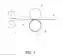
FIG. 1 shows schematically one underlay material manufacturing arrangement according to the invention,
FIG. 2 shows schematically one underlay material of the invention in cross-section, and
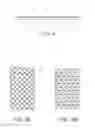
FIGS. 3A and 3B illustrate examples of air provision patterns made up of grooves in an underlay material of the invention.
FIG. 1 shows schematically one manufacturing arrangement of the invention, which comprises a reel 2 composed of a sheet material 1 in the form of a web, a reel 4 composed of a cellular plastic material 3 in the form of a web, as well as a pair of press rolls 5 and 6.
In the arrangement of FIG. 1, the sheet material 1 in the form of a web, which in this example consists of plastic sheet, is fed from the reel 2 to a location between the pair of press rolls 5 and 6 with a top surface of the sheet material 1 placing itself against a surface of the smooth roller 5. The cellular plastic material 3 in the form of a web is fed from the reel 4 to a location between the pair of press rolls 5 and 6, such that a top surface of the cellular plastic material 3 places itself against the sheet material 1 and its bottom surface against the roll 6 provided with protrusions 7, 7′.
Either the entire roll 6 or the protrusions 7, 7′ of the roll 6 have been heated, for example with heating resistors, the cellular plastic material 3 set against the protrusions 7, 7′ being melted thereby.
The manufacture of an underlay material 8 proceeds in the sequence of FIG. 1 simply in such a way that the web type sheet material 1 and cellular plastic material 3 are web-fed from the reels 2 and 4 to a location between the pair of press rolls 5 and 6, the underlay material being produced thereafter simply by rotating the pair of press rolls 5 and 6. At this time, the pair of press rolls has the hot protrusions 7, 7′ of its roll 6 melting some of the cellular plastic material 3 in areas coincident with the protrusions in response to both heat and pressure, whereby the cellular plastic material collapses and thereby bonds over its melted areas to the sheet material 1 at the latest when reaching a nip point of the pair of press rolls, i.e. at the point where a surface of the roll 5 and an end surface of the roll's 6 protrusions 7, 7′ are at a minimum distance from each other.
In the embodiment of FIG. 1, the roll 6 has its protrusions 7, 7′ designed in such a way that the protrusions 7 melt grooves in the cellular plastic material 3 longitudinal of its web and the protrusions 7′ melt grooves in the cellular plastic material 3 lateral of its web. Hence, the grooves providing an air provision for the manufactured underlay material 8 make up a pattern of squares on the bottom surface of the cellular plastic material 3.
Temperature of the roll 6 and/or its protrusions 7, 7′ is set sufficiently high for melting the cellular plastic material 3. This temperature may also accomplish partial melting of the sheet material 1, which in turn enhances bonding of the cellular plastic material 3 to the sheet material 1. In order to prevent excessive melting of the sheet material 1, the roll 5 and/or its surface can be cooled as necessary. In view of melting for example a cellular plastic material of polyethylene, the temperature suitable for the roll 6 and/or its protrusions 7, 7′ is about 140° C.
FIG. 2 shows schematically a cross-section of one underlay material 8, which is manufactured with a solution according to the invention and made up of a sheet material 1 and a cellular plastic material 3. It can be seen from this cross-section how a cellular plastic material 10 melted and packed on the bottom of grooves 9 in connection with manufacturing the underlay material 8 has bonded to the sheet material 1 for producing the underlay material 8.
FIGS. 3A and 3B illustrate optional air provision patterns defined by grooves 9 made in a cellular plastic material on the bottom surface of an underlay material 8. As indicated by these patterns, the air provision-establishing continuous grooves 9 can be formed on the surface of a cellular plastic material quite arbitrarily for designing various patterns as long as such grooves nevertheless make up continuous paths across the surface area of the underlay material 8 for the expulsion and removal from under the underlay material of possible moisture building up on a bottom surface of the underlay material.
The solution of the invention is not bound to the use of plastic membranes as a sheet material 1, but other suitable sheet materials can also be used, such as for example paper or cardboard.
The cellular plastic material 3 employed in the solution of the invention comprises preferably a suitable flexible foamed polymer, such as for example cellular polyethylene or polypropylene plastic 1-5 mm in thickness.
The finished underlay material 8 is preferably about 1-5 mm in thickness.
Regarding the embodiments shown in the figures and described above, it should be appreciated that these are just examples of solutions according to the invention and, as such, by no means limiting the invention. The scope of protection for the invention is defined in the appended claims.
Claims
1. A method for manufacturing an underlay material (8) to be set under parquet or a laminate, said underlay material consisting of a sheet material layer (1) and a flexible cellular plastic material layer (3) bonded under the sheet material layer, and a bottom surface of said cellular plastic layer being processed for providing an air space, wherein the bottom surface of the cellular plastic material layer (3) is processed by melting the cellular plastic material locally for providing an air space (9) and for simultaneously bonding the cellular plastic material layer to the sheet material layer (1).
2. A method according to claim 1, wherein the melting and bonding of the cellular plastic material layer (3) to the sheet material layer (1) is conducted by conveying the material layers through between rolls 5 and 6 set in opposition to each other, whereby the roll (6) placing itself against the cellular plastic material has its surface formed with uniform protrusions (7, 7′), the roll placing itself against the cellular plastic material layer having at least its protrusions heated.
3. A method according to claim 1, wherein the cellular plastic material layer (3) is by melting formed with at least two sets of continuous and parallel grooves (9), the grooves of various sets crossing each other to make up a pattern of squares or lozenges on the surface of the cellular plastic material layer.
4. A method according to claim 2, wherein the cellular plastic material layer (3) is by melting formed with at least two sets of continuous and parallel grooves (9), the grooves of various sets crossing each other to make up a pattern of squares or lozenges on the surface of the cellular plastic material layer.
5. A method according to claim 1, wherein the sheet material layer (1) is made of plastic, paper or cardboard.
6. A method according to claim 2, wherein the sheet material layer (1) is made of plastic, paper or cardboard.
7. A method according to claim 3, wherein the sheet material layer (1) is made of plastic, paper or cardboard.
8. A method according to claim 4, wherein the sheet material layer (1) is made of plastic, paper or cardboard.
9. A method according to claim 1, wherein the cellular plastic material layer (3) is made of a foamed polymer or polymer blend.
10. A method according to claim 2, wherein the cellular plastic material layer (3) is made of a foamed polymer or polymer blend.
11. A method according to claim 3, wherein the cellular plastic material layer (3) is made of a foamed polymer or polymer blend.
12. A method according to claim 4, wherein the cellular plastic material layer (3) is made of a foamed polymer or polymer blend.
13. A method according to claim 1, wherein the cellular plastic material layer (3) is made of a foamed polymer or polymer blend and is in the form of a material web.
14. A method according to claim 2, wherein the cellular plastic material layer (3) is made of a foamed polymer or polymer blend and is in the form of a material web.
15. A method according to claim 3, wherein the cellular plastic material layer (3) is made of a foamed polymer or polymer blend and is in the form of a material web.
16. A method according to claim 4, wherein the cellular plastic material layer (3) is made of a foamed polymer or polymer blend and is in the form of a material web.
17. A method according to claim 1, wherein the sheet material layer (1) is made of plastic, paper or cardboard and is in the form of a material web.
18. A method according to claim 2, wherein the sheet material layer (1) is made of plastic, paper or cardboard and is in the form of a material web.
19. A method according to claim 3, wherein the sheet material layer (1) is made of plastic, paper or cardboard and is in the form of a material web.
20. A method according to claim 4, wherein the sheet material layer (1) is made of plastic, paper or cardboard and is in the form of a material web.
Images & Drawings included:

Sources:
- United States Patent and Trademark Office - verify current appl. status at the USPTO↗
Similar patent applications:
Recent applications in this class:
- » 20250033340 2025-01-30
Method for laminating a tufted good with a film to achieve tuft lock - » 20240165939 2024-05-23
Rapidly pressing mixtures of paper and plastic to targeted thickness and density - » 20240140082 2024-05-02
LASER-BONDED OPTICAL ASSEMBLIES - » 20240025167 2024-01-25
Methods To Directly Join Metals To Polymer/Polymer Composites Using Functionally Active Insert Layer - » 20210162728 2021-06-03
Spout pouch and method of making same - » 20210146672 2021-05-20
COMPOSITE TEXTILE AND METHOD OF PRODUCING SAME - » 20210001616 2021-01-07
METHOD FOR MANUFACTURING A PANEL INCLUDING A REINFORCEMENT SHEET - » 20190039364 2019-02-07
Tack and bond adhesive system and method for layered object manufacture - » 20170355180 2017-12-14
Method for manufacturing a panel including a reinforcement sheet, and a floor panel - » 20170253015 2017-09-07
COMPOSITE TEXTILE AND METHOD OF PRODUCING SAME