Heat exchanger having a baffle
US20170153071A1
2017-06-01
15/327,527
2015-07-24
✅ Patent granted
US 10,126,074 B2
2018-11-13
WO; PCT/EP2015/067081; 20150724
WO; WO2016/012621; 20160128
Davis Hwu
Osha Liang LLP
2035-07-24
Abstract:
The invention is related to a heat exchanger (1), which comprises:
-
- at least one column of parallel tubes (2) which are arranged in a stack and which define a longitudinal direction;
- a housing (3) inside which the tubes (2) are housed, the tubes (2) being separated from one another, so as to configure a channel for the passage of cooling fluid consisting of:
- passage sections (4) between tubes (2) that are contiguous in the direction of the stack;
- passage sections (5) between tubes and housing (3); and
- baffles (6, 7) that deflect the cooling fluid.
According to the invention, the baffles are at least two lamellar bodies (6, 7) of a single piece arranged in a plane perpendicular to the longitudinal direction.
Inventors:
- Juan Carlos De Francisco Moreno 5 🇪🇸 Zaragoza, Spain
- Yolanda Bravo Rodriguez 3 🇪🇸 Zaragoza, Spain
- Fernando Puertolas Sanchez 3 🇪🇸 Zaragoza, Spain
- Francisco Lopez Lazaro 3 🇪🇸 Zaragoza, Spain
Assignee:
- Valeo Termico, S.A. 9 🇪🇸 Zaragoza, Spain
Applicant:
Interested in similar patents?
Get notified when new applications in this technology area are published.
Classification:
F28D7/16 IPC
Heat-exchange apparatus having stationary tubular conduit assemblies for both heat-exchange media, the media being in contact with different sides of a conduit wall the conduits being arranged in parallel spaced relation
F28D7/1684 » CPC further
Heat-exchange apparatus having stationary tubular conduit assemblies for both heat-exchange media, the media being in contact with different sides of a conduit wall the conduits being arranged in parallel spaced relation the conduits having a non-circular cross-section
F28D2021/008 » CPC further
Heat-exchange apparatus not covered by any of the groups - ; Other heat exchangers for particular applications; Heat exchange systems not otherwise provided for for vehicles
F28F9/22 » CPC main
Casings; Header boxes; Auxiliary supports for elements; Auxiliary members within casings Arrangements for directing heat-exchange media into successive compartments, e.g. arrangements of guide plates
F28D7/00 IPC
Heat-exchange apparatus having stationary tubular conduit assemblies for both heat-exchange media, the media being in contact with different sides of a conduit wall
F28D21/0003 » CPC further
Heat-exchange apparatus not covered by any of the groups - ; Recuperative heat exchangers the heat being recuperated from exhaust gases
F02B29/0462 » CPC further
Engines characterised by provision for charging or scavenging not provided for in groups , or - ; Details thereof; Cooling of air intake supply; Constructional details of the heat exchangers, e.g. pipes, plates, ribs, insulation, materials, or manufacturing and assembly Liquid cooled heat exchangers
F02M26/32 » CPC further
Engine-pertinent apparatus for adding exhaust gases to combustion-air, main fuel or fuel-air mixture, e.g. by exhaust gas recirculation [EGR] systems; Arrangement or layout of EGR passages, e.g. in relation to specific engine parts or for incorporation of accessories with coolers in the recirculation passage; Constructional details of the coolers, e.g. pipes, plates, ribs, insulation or materials Liquid-cooled heat exchangers
F28D21/00 IPC
Heat-exchange apparatus not covered by any of the groups -
F02B29/04 IPC
Engines characterised by provision for charging or scavenging not provided for in groups , or - ; Details thereof Cooling of air intake supply
F02M26/29 » CPC further
Engine-pertinent apparatus for adding exhaust gases to combustion-air, main fuel or fuel-air mixture, e.g. by exhaust gas recirculation [EGR] systems; Arrangement or layout of EGR passages, e.g. in relation to specific engine parts or for incorporation of accessories with coolers in the recirculation passage Constructional details of the coolers, e.g. pipes, plates, ribs, insulation or materials
F28D2021/0082 » CPC further
Heat-exchange apparatus not covered by any of the groups - ; Other heat exchangers for particular applications; Heat exchange systems not otherwise provided for for vehicles Charged air coolers
Description
The present invention relates to a heat exchanger provided with one or more baffles that guide the cooling flow in order to obtain optimum exchange of heat between cooling fluid and cooled fluid.
CONTEXT OF THE INVENTION
Already known in the automotive sector are heat exchangers which comprise:
-
- at least one column of parallel tubes of rectangular cross section which are arranged in a stack and which define a longitudinal direction;
- a housing inside which the tubes are housed, the tubes being equipped on their upper and lower sides with protrusions intended to keep the tubes assembled with one another and with the housing with a separation so as to configure a channel for the passage of cooling fluid consisting of:
- passage sections between tubes that are contiguous in the direction of the stack;
- passage sections between tubes and housing.
Consequently, the cooling fluid is forced to pass via said passage sections, in contact with the external surface of the tubes, so that an exchange of heat takes place between the fluid that is to be cooled which passes along the inside of the tubes and the cooling fluid.
In general, for reasons of space, there are very few options as to how to configure the inlets and outlets either of the cooled fluid, which enters via one end of the tubes and leaves via the other end, namely which travels through the heat exchanger in the longitudinal direction, or of the cooling fluid, which enters at the upper part via the front of the exchanger to leave via the rear part, preferably on the side.
This configuration, which can be varied in numerous ways, provides only limited control over the configuration of the thermal gradients between the two fluids because it is possible that exchanger zones, particularly the corners remote from the inlets and outlets of cooling fluid and also referred to as stagnation zones will remain, in which the flow of cooling fluid is lower and as a result in which the cooling efficiency is compromised.
In order to reduce stagnation zones, the use of baffles that deflect the cooling fluid, which constitute obstacles that are placed in the passage sections with a view to configuring the flow more effectively is known.
Nevertheless, there does not yet exist any multifunction solution that is compatible with a method of assembling tubes and baffles.
DESCRIPTION OF THE INVENTION
In order to fill this gap, there is proposed a heat exchanger, which comprises:
-
- at least one column of parallel tubes which are arranged in a stack and which define a longitudinal direction;
- a housing inside which the tubes are housed, the tubes being separated from one another, so as to configure a channel for the passage of cooling fluid consisting of:
- passage sections between tubes that are contiguous in the direction of the stack;
- passage sections between tubes and housing; and
- baffles that deflect the cooling fluid;
and which is characterized in that the baffles are at least two lamellar bodies of a single piece arranged in a plane perpendicular to the longitudinal direction and cut out in such a way that each has: - a first section able to partially obstruct a passage section between tubes and housing,
- extensions which extend from said first section at right angles thereto and which are able to obstruct passage sections between tubes that are contiguous in the direction of the stack,
the length of the extensions of each of the lamellar bodies being such that the extensions of one of the lamellar bodies overlap with the extensions of the other lamellar body so that each lamellar body can be introduced laterally with respect to the tubes and constitute a baffle that deflects the cooling fluid.
For preference, the tubes are equipped on their upper and lower sides with protrusions intended to keep the tubes assembled with each other and with the housing.
For preference, the tubes are of rectangular cross section.
Advantageously, the exchanger comprises two contiguous columns of parallel tubes of rectangular cross section arranged in the stack.
For preference, each lamellar body comprises a terminal section parallel to the extensions and which obstructs the passage section for cooling fluid between the housing and the lower or upper tube of the stack.
Advantageously, the terminal section of the lamellar bodies comprises cutouts able to collaborate with the protrusions of the housing.
More advantageously, the exchanger comprises an upper frontal inlet for cooling fluid and a lateral posterior outlet for cooling fluid, two lamellar bodies arranged to obstruct the passage section for cooling fluid via the upper part immediately downstream of the upper frontal inlet for cooling fluid and two lamellar bodies arranged to obstruct the passage section for cooling fluid via the lower part immediately upstream of the lateral posterior outlet for cooling fluid.
Finally, each of the first sections comprises flanges which extend at right angles from their edge for contact with the tubes so that they constitute plates for fixing to the tubes.
BRIEF DESCRIPTION OF THE FIGURES
For a better understanding of what has just been explained, drawings are attached which schematically and solely by way of nonlimiting example depict one practical way of embodying the exchanger according to the invention.
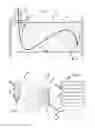
FIG. 1 is a cross section in elevation of the exchanger according to the invention.
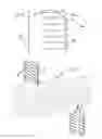
FIG. 2 is an exploded perspective view of the exchanger according to the invention.
FIG. 3 is a face-on view.
FIGS. 4 and 5 are side and front elevations of one of the individual components that make up the baffle means.
FIG. 6 is an exploded perspective view of a set of tubes and of two pairs of baffle components.
DESCRIPTION OF ONE PREFERRED EMBODIMENT
As may be seen from the figures, the invention relates to a heat exchanger 1, which comprises:
-
- at least one column of parallel tubes 2, very preferably of rectangular cross section, which are arranged in a stack and which define a longitudinal direction;
- a housing 3 inside which the tubes 2 are housed, the tubes 2 being separated from one another, so as to configure a channel for the passage of cooling fluid consisting of:
- passage sections 4 between tubes 2 that are contiguous in the direction of the stack;
- passage sections 5 between tubes and housing 3; and
- baffles 6, 7 that deflect the cooling fluid;
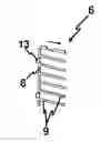
and which is characterized in that the baffles are at least two lamellar bodies 6, 7 of a single piece arranged in a plane perpendicular to the longitudinal direction and cut out in such a way that each has: - a first section 8 able to partially obstruct a passage section 5 between tubes and housing 3,
- extensions 9 which extend from said first section 8 at right angles thereto and which are able to obstruct passage sections 4 between tubes 2 that are contiguous in the direction of the stack,
the length of the extensions 9 of each of the lamellar bodies 6, 7 being such that the extensions 9 of one of the lamellar bodies 6 overlap with the extensions 9 of the other lamellar body 7 so that each lamellar body 6, 7 can be introduced laterally with respect to the tubes and constitute a baffle that deflects the cooling fluid.
Consequently, in other words, the baffles are made up of two components which are comb-shaped and which are assembled by the sides by introducing the teeth of the comb between the tubes 2. The ends of these “combs” become superposed to constitute the equivalent of a one-piece component.
The fact that assembly is performed from the side at right angles by contrast with an assembly in parallel, namely by means of introduction in the longitudinal direction, avoids the need to provide cutouts to correspond with the connecting protrusions on the components that make up the baffle. Such cutouts would be numerous and that would therefore involve undesirable choices of passage for the cooling fluid.
As can be seen in the figures, the tubes 2 are equipped on their upper and lower sides with protrusions P intended to keep the tubes 2 assembled with each other and with the housing 3.
As can be seen in the figures, according to a preferred embodiment, the exchanger comprises two contiguous columns of parallel tubes 2 of rectangular cross section arranged in the stack. In that case obviously the passage section between contiguous tubes in the horizontal direction is not plugged by the components or “combs”, but this is a cross section of little significance.
Each lamellar body 6, 7 comprises a terminal section 10 parallel to the extensions 9 and which obstructs the passage section for cooling fluid between the housing 3 and the lower or upper tube of the stack. This terminal section 10 can be assembled by brazing to the upper (lower) surface of the upper (lower) tube in order to contribute to the fixing of the baffles to the tubes.
The exchanger comprises an upper frontal inlet 11 for cooling fluid and a lateral posterior outlet 12 for cooling fluid, two lamellar bodies 6, 7 arranged to obstruct the passage section for cooling fluid via the upper part immediately downstream of the upper frontal inlet 11 for cooling fluid and two lamellar bodies 6′, 7′ arranged to obstruct the passage section for cooling fluid via the lower part immediately upstream of the lateral posterior outlet 12 for cooling fluid.
The overall modification to the flow of cooling fluid that is obtained with the two pairs of baffle components can be discerned in FIG. 1. Obviously, any combination of baffle components can be used in order to achieve the desired flow pattern.
Each of the first sections 8 comprises flanges 13 which extend at right angles from their edge for contact with the tubes so that they constitute plates for laterally fixing to the tubes 2.
Finally, the components that constitute the baffles comprise cutouts 14 intended to allow the internal assembly protrusions for the housing to pass, because the housing is mounted by slipping it over everything once the baffles have been placed on the tubes and fixed to the latter.
As can be seen for example in FIGS. 1 and 3, the components cover between half and two-thirds of the passage section, even though in each case it is possible to determine the optimum number of pairs of components in order to obtain the desired flow of cooling fluid.
Although reference has been made to one concrete embodiment of the invention, it is obvious to a person skilled in the art that the exchanger described here can be varied and modified in numerous ways and that all the details mentioned can be replaced by technically equivalent others, without thereby departing from the umbrella of protection defined by the attached claims.
Claims
1. A heat exchanger comprising:
at least one column of parallel tubes which are arranged in a stack and which define a longitudinal direction;
a housing inside which the tubes are housed, the tubes being separated from one another, so as to configure a channel for the passage of cooling fluid consisting of:
passage sections between tubes that are contiguous in the direction of the stack;
passage sections between tubes and housing; and
baffles that deflect the cooling fluid;
wherein the baffles are at least two lamellar bodies of a single piece arranged in a plane perpendicular to the longitudinal direction and cut out in such a way that each has:
a first section able to partially obstruct a passage section between tubes and housing, and
extensions which extend from said first section at right angles thereto and which are able to obstruct passage sections between tubes that are contiguous in the direction of the stack,
the length of the extensions of each of the lamellar bodies being such that the extensions of one of the lamellar bodies overlap with the extensions of the other lamellar body so that each lamellar body is introduced laterally with respect to the tubes and constitute a baffle that deflects the cooling fluid.
2. The exchanger as claimed in claim 1, in which the tubes are equipped on their upper and lower sides with protrusions intended to keep the tubes assembled with each other and with the housing.
3. The exchanger as claimed in claim 1, in which the tubes are of rectangular cross section.
4. The exchanger as claimed in claim 1, which comprises two contiguous columns of parallel tubes of rectangular cross section arranged in the stack.
5. The exchanger as claimed in claim 1, in which each lamellar body comprises a terminal section parallel to the extensions and which obstructs the passage section for cooling fluid between the housing and the lower or upper tube of the stack.
6. The exchanger as claimed in claim 2, in which the terminal section of the lamellar bodies comprises cutouts able to collaborate with the protrusions of the housing.
7. The exchanger as claimed in claim 1, which comprises an upper frontal inlet for cooling fluid and a lateral posterior outlet for cooling fluid, two lamellar bodies arranged to obstruct the passage section for cooling fluid via the upper part immediately downstream of the upper frontal inlet for cooling fluid and two lamellar bodies arranged to obstruct the passage section for cooling fluid via the lower part immediately upstream of the lateral posterior outlet for cooling fluid.
8. The exchanger as claimed in claim 1, in which each of the first sections comprises flanges which extend at right angles from their edge for contact with the tubes so that they constitute plates for fixing to the tubes.
Images & Drawings included:
Sources:
- United States Patent and Trademark Office - verify current appl. status at the USPTO↗
Similar patent applications:
- » 20190360756
HEAT EXCHANGER BAFFLE ASSEMBLY AND TUBE PATTERN FOR RADIAL FLOW HEAT EXCHANGER AND FLUID HEATING SYSTEM INCLUDING THE SAME - » 20250271220
HEAT EXCHANGER AND BAFFLE OF THE HEAT EXCHANGER - » 20220260326
HEAT EXCHANGER BAFFLES AND METHODS FOR MANUFACTURING THE SAME - » 20210018278
Continuous helical baffle heat exchanger - » 20190063853
Continuous helical baffle heat exchanger - » 20060076126
Heat exchanger baffle - » 20210092827
Notched baffled heat exchanger for circuit boards - » 20220065495
HEAT EXCHANGER BAFFLE ASSEMBLY WITH HORIZONTAL GAP - » 20200378697
Helically baffled heat exchanger - » 20230021014
Continuous helical baffle heat exchanger
Recent applications in this class:
- » 20250257957 2025-08-14
INTERWOVEN HEAT EXCHANGER CORE WITH END FACE FEATURES - » 20250129998 2025-04-24
Microchannel Heat Exchanger And A Fluid Distributor Thereof - » 20250003703 2025-01-02
Heat Exchanger - » 20240271889 2024-08-15
FLOW-MODIFYING HEAT EXCHANGER CORE TUBES - » 20240255240 2024-08-01
REFRIGERANT DISTRIBUTION DEVICE AND HEAT EXCHANGER - » 20240240882 2024-07-18
SHELL-AND-TUBE HEAT EXCHANGER AND METHOD FOR CHANGING THE TEMPERATURE OF A MEDIUM - » 20240167774 2024-05-23
FLUID DISTRIBUTION TANK FOR A TUBE OF A HEAT EXCHANGER - » 20240060732 2024-02-22
TUBE HEAT EXCHANGER - » 20230059671 2023-02-23
Continuous helical baffle heat exchanger - » 20230058788 2023-02-23
Continuous helical baffle heat exchanger
Recent applications for this Assignee:
- » 20210381472 2021-12-09
Heat exchanger for gases, in particular engine exhaust gases - » 20210302111 2021-09-30
REINFORCED HEAT EXCHANGER COMPRISING A STACK OF PLATES - » 20210207896 2021-07-08
CIRCULATION DUCT FOR CONVEYING A FLUID OF A HEAT EXCHANGER, AND HEAT EXCHANGER - » 20160265488 2016-09-15
GAS HEAT EXCHANGER, IN PARTICULAR FOR THE EXHAUST GASES OF AN ENGINE - » 20150308387 2015-10-29
GAS HEAT EXCHANGER, IN PARTICULAR FOR EXHAUST GASES OF AN ENGINE - » 20150253085 2015-09-10
HEAT EXCHANGE FOR GAS, PARTICULARLY THE EXHAUST GASES OF AN ENGINE - » 20150027673 2015-01-29
Heat exchanger for gases, in particular for the exhaust gases of an engine - » 20070131400 2007-06-14
Heat exchanger for gases, especially for engine exhaust gases