Firearm with a hammer mechanism
US20170153079A1
2017-06-01
15/365,010
2016-11-30
✅ Patent granted
US 9,891,016 B2
2018-02-13
-
-
Stephen Johnson
Paul D. Bianco | Katharine Davis | Fleit Gibbons Gutman Bongini & Bianco PL
2036-11-30
Abstract:
A firearm with a housing, a barrel fastened to the housing, a bolt for closure of a chamber provided in barrel, and a hammer mechanism to operate a firing pin arranged in the bolt. The hammer mechanism contains a hammer strut arranged between the firing pin and a cocking piece, offset parallel to the firing pin.
Assignee:
- L & O Hunting Group GmbH 3 🇩🇪 Isny, Germany
- L & O Hunting Group GmbH 4 🇩🇪 Isny, Germany
Applicant:
Interested in similar patents?
Get notified when new applications in this technology area are published.
Classification:
F41A17/80 » CPC further
Safety arrangements, e.g. safeties; Hammer safeties, i.e. means for preventing the hammer from hitting the cartridge or the firing pin Thumb-operated sliding safeties mounted on the upside of the stock, e.g. for shotguns
F41A19/13 » CPC further
Firing or trigger mechanisms; Cocking mechanisms; Mechanical firing mechanisms, e.g. counterrecoil firing, recoil actuated firing mechanisms Percussion or firing pins, i.e. fixed or slidably-mounted striker elements; Mountings therefor
F41A19/44 » CPC further
Firing or trigger mechanisms; Cocking mechanisms; Mechanical firing mechanisms, e.g. counterrecoil firing, recoil actuated firing mechanisms having at least one hammer in bolt-action guns Sear arrangements therefor
F41A3/34 » CPC further
Breech mechanisms, e.g. locks; Bolt action, i.e. the main breech opening movement being parallel to the barrel axis; Rigid bolt locks, i.e. having locking elements rigidly mounted on the bolt or bolt handle and on the barrel or breech-housing respectively the bolt additionally effecting a sliding movement transverse to the barrel axis
F41A5/26 » CPC further
Mechanisms or systems operated by propellant charge energy for automatically opening the lock gas-operated Arrangements or systems for bleeding the gas from the barrel
F41A19/14 » CPC main
Firing or trigger mechanisms; Cocking mechanisms; Mechanical firing mechanisms, e.g. counterrecoil firing, recoil actuated firing mechanisms Hammers, i.e. pivotably-mounted striker elements; Hammer mountings
F41A19/30 » CPC further
Firing or trigger mechanisms; Cocking mechanisms; Mechanical firing mechanisms, e.g. counterrecoil firing, recoil actuated firing mechanisms having only slidably-mounted striker elements, i.e. percussion or firing pins the percussion or firing pin being movable relative to the breech-block propelled by a spring under tension in bolt-action guns
Description
FIELD OF THE DISCLOSURE
The disclosure relates to a firearm with a hammer mechanism.
BACKGROUND
This type of firearm is known under the name Sauer 303. It also contains a housing, a barrel fastened to the housing, a bolt assembly for closure of a cartridge chamber provided in the barrel and a hammer mechanism to activate a firing pin arranged in the bolt assembly. The hammer mechanism in this known gas-operated firearm consists of a hammer mounted to rotate on a trigger housing, which acts directly on the firing pin arranged in the bolt assembly.
SUMMARY
A firearm of the type just mentioned with an alternative hammer mechanism is disclosed. Expedient modifications and advantageous embodiments are also disclosed.
In an embodiment, the hammer mechanism in the firearm according to the disclosure has a hammer strut arranged between the firing pin and a cocking piece offset parallel to the firing pin. A connection can be made via this hammer strut between the cocking piece arranged in the housing behind a magazine shaft and the firing pin arranged in the bolt assembly.
The hammer strut expediently runs above and along a downwardly open magazine shaft arranged in the housing and in a particularly advantageous embodiment can be guided to move in a longitudinal groove on the inside of a rear part of the barrel parallel to the center line of the barrel.
In a preferred embodiment, the hammer strut has a front crosspiece and a rear crosspiece for connection to the firing pin and the cocking piece. The crosspieces expediently protrude inward for contact with the cocking piece and activation of the offset firing pin.
A cocking element cooperating with the firing pin and operable by the hammer strut can be arranged on the bolt assembly to activate the firing pin in another advantageous embodiment. The cocking element can be designed in the form of a lever and attached with one end to the rear end of the bolt assembly to pivot about a pin offset laterally relative to the longitudinal axis of the bolt assembly and perpendicular to the longitudinal axis. The other end of the lever-like cocking element can be designed as a free end protruding laterally relative to the bolt assembly for contact with the hammer strut.
The cocking element in another advantageous embodiment can be arranged to pivot in a transverse groove on the rear end of the bolt assembly and designed in the form of a wedge with an oblique surface facing the firing pin.
The cocking element can be expediently arranged to rotate on a breech lock mount insertable into the housing around a transverse pin between a rear starting position and a front firing position. The cocking piece is acted upon by a cocking spring, which is stretched between the cocking piece and a cocking lever movable by means of a cocking slide between a rear uncocked position and a front cocked position. The cocking spring is therefore only tensioned when the locking lever is moved into a cocked position via the cocking slide.
BRIEF DESCRIPTION OF THE DRAWINGS
Additional details and advantages of the disclosure are apparent from the following description of a preferred embodiment example with reference to the drawing. In the drawing:
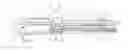
FIG. 1 shows a partial longitudinal section of gas-operated firearm;
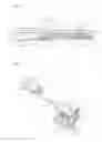
FIG. 2 shows a breech lock of the gas-operated firearm depicted in FIG. 1;
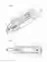
FIG. 3 a partial cutaway perspective view of the rear part of the gas-operated firearm depicted in FIG. 1 with the breech lock in an unlocked position;
FIG. 4 shows a longitudinal section of the rear part of the gas-operated firearm depicted in FIG. 3 with the breech lock in the unlocked position;
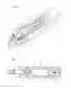
FIG. 5 shows a partial cutaway perspective view of the rear part of the gas-operated firearm depicted in FIG. 1 with the breech lock in a locked position and
FIG. 6 shows a longitudinal section of the rear part of the gas-operated firearm depicted in FIG. 5 with the breech lock in the locked position.
DETAILED DESCRIPTION
A partial longitudinal section of a gas-operated firearm is depicted in FIG. 1 with a receiver or housing 1, a barrel 2 mounted on housing 1 and a front shaft 3. A guide rod 4 protruding forward when viewed in the direction of firing and parallel to the center line of barrel 2 is fastened to housing 1. A bolt-operating device 5 for movement of a bolt 6 depicted in FIGS. 2 to 6 is guided to move on the guide rod 4 freely protruding forward and not fastened to barrel 2. A recoil spring 7 is also arranged on the guide rod 4, via which the bolt-operating device 5 is forced forward. The front shaft 3 with its front end viewed in the direction of firing is fastened on the guide rod 4 via external threads 8 on the front free end of guide rod 4 and a threaded sleeve 9 provided with corresponding internal threads.
The bolt-operating device 5 has a carrier 10 guided to move on the guide rod 4 and two push rods 11 fastened to carrier 10. Each rear free end of the two push rods 11, viewed in the direction of firing, contains a ramp-like control cam (not shown here), via which the bolt 6, provided with lateral protrusions 12 and depicted in FIG. 2, can be moved between an upper locked position depicted in FIG. 3 and a lower unlocked position by displacement of the operating device 5. The bolt-operating device 5 is forced forward, viewed in the direction of firing, via the bolt spring arranged on guide rod 4 and stretched between housing 1 and carrier 10. In this position, the bolt 6 is forced upwards, so that a locking block 13 protruding upwards from the top on bolt 6 enters into engagement according to FIG. 3 in a locking groove 14 on barrel 2. If the bolt-operating device 5, on the other hand, is pushed rearward, viewed in the firing direction, either via a bolt handle 15 or the gas pressure during firing of a shot against the force of the bolt spring 7, the bolt 6 can be moved downwardly due to the control cam and the locking block 13 can disengage from the locking groove 14 on barrel 2 for opening of the bolt.
It follows from FIG. 1 that the barrel 2 has a rear part 16 that can be mounted on housing 1 and firmly connected to it and a front part 17 freely protruding from lock housing 1. The rear part 16 enlarged in diameter relative to front part 17 of the barrel 2 has a front area closed in the peripheral direction and a rear area opened downwardly. A side ejection opening 18 for cartridge ejection is provided in the tunnel-like rear area with the cross section of an annular segment on the rear part 16 of barrel 2. The rear part 16 and the front part 17 of barrel 2, when viewed in the direction of firing, are made from a single piece in the depicted embodiment. The two parts 16 and 17 of barrel 2, however, can also be made as individual parts, connected and firmly joined to each other, for example, by soldering or another appropriate means of connection.
Two radially protruding retaining pins 19 are provided on the rear part 16 of barrel 2 lying on housing 1 for fastening of barrel 2 to housing 1. The retaining pins 19 provided with external threads can be radially inserted into the rear part of barrel 2 or directly molded onto the barrel 2. The retaining pins 19 are designed for engagement in two holes 20 arranged next to each other in a protruding support part 21 of housing 1. The barrel 2 can be fastened to housing 1 via the two retaining pins 20 with the freely protruding front part 17 through two nuts 22 accessible from the bottom of housing 1. The rear end of the front shaft 3 is also fastened to the support part 21 of lock housing 1. A downward protruding gas-discharge block 23 is provided in the middle area of the barrel 2 on front part 17.
As follows from FIG. 1, the gas-discharge block 23 has a gas cylinder 24 with a gas-discharge hole 25 opening into barrel 2 and a pressure piston 26 guided to move axially in gas cylinder 24. The pressure piston 26 contains a piston rod 27 extending through a rear hole in the gas-discharge block 24, which cooperates with the support 10 of the bolt-operating device 5 to move the bolt 6 into the unlocked position.
A chamber 28 provided in barrel 2 is closed off downward by the bolt 6 depicted in cross section in FIGS. 3 and 4. A firing pin 29 is guided to move axially in the bolt 6. A firing pin spring 30 arranged around firing pin 20 is also accommodated in the bolt 6, through which the front tip 31 of the firing pin 29 is forced into a retracted position. The rear end 32 of firing pin 29, viewed in the direction of firing, lies on a lever-like cocking element 34 arranged to pivot in a transverse groove 33 on the rear end of bolt 6. The lever-like cocking element 34 is connected to the bolt 6 with its one end to pivot about a pin 35 laterally offset relative to the longitudinal axis of the bolt 6 and perpendicular to the longitudinal axis. The free other end 36 of the lever-like cocking element 34 protrudes laterally from the bolt 6 according to FIG. 2.
A firearm lock with a cocking piece 37 movable between a rear initial position and a front triggering position for activation of the firing pin 29 arranged in bolt 6 via a hammer strut 38 and the lever-like cocking element 33 on bolt 6 is shown in FIG. 2. A hammer mechanism for operation of the firing pin 29 arranged in the bolt 6 is formed by the cocking piece 37, the hammer strut 38 and the lever-like cocking element 33. The hammer strut 38 offset parallel to the center axis of the bolt 6 has a front crosspiece 39 that comes to a stop on its front end with the protruding end 36 with a lever-like cocking element 33 and a rear crosspiece 40 that cooperates with the cocking piece 37.
The cocking piece 37 is mounted to rotate on a lock carrier 41 insertable into housing 1 around a cross pin 42. A slide stop 43 is also arranged on the lock carrier 41, via which the cocking element 37 can be held in the rear initial position or released via a trigger not shown here for firing of a shot. A locking lever 44 is also linked on the lock carrier 41 to pivot about another cross pin 45 between a rear uncocked position and a front cocked position. A cocking spring 46 is stretched between the locking lever 44 and the cocking piece 37. Displacement of the locking lever 44 between the rear uncocked position and the front cocked position occurs through a cocking slide 47, which contains a lower part 48 connected to the locking lever 44 and an upper part 49 connected to it. The slide-like upper part 49 operable by the thumb of a shooter is guided according to FIG. 3 in a recess 50 on the oblique top of a rear end part 51 of housing 1 so that the cocking slide 47 can be moved between a lower safe position and an upper off-safe position.
It is apparent in FIG. 3 that the hammer strut 38 is guided to move in the longitudinal groove 42 on the inside of the tunnel-like rear part 16 of barrel 2 offset laterally and parallel to the firing pin 29 and also the center line of barrel 2. The front crosspiece 39 and the rear crosspiece 40 of the hammer strut 38 protrude inwardly, so that they can come to a stop with the cocking element 34 in the bolt 6 and the cocking piece 37. The hammer strut 38 runs above and along a downwardly open magazine shaft 53 arranged in housing 1, into which a magazine can be inserted. The connection between the cocking piece 37 arranged behind the magazine shaft 53 and the firing pin 39 arranged in bolt 6 can be made via hammer strut 38. The lever-like cocking element 34 according to FIG. 4 is designed in the form of wedge with an oblique surface 54 facing the firing pin 29.
The breech lock is shown in an unlocked position in FIGS. 3 and 4. The cocking slide 47 is situated in the lower safe position so that the locking lever 44 is also situated in a rear locked position and the main spring 46 is unlocked. In this position of the cocking slide 47 the cocking piece 37 held in the rear starting position cannot be knocked off even during operation of the trigger.
Only when the cocking slide 47 is pushed upward into the upper off-safe position depicted in FIGS. 5 and 6 does the locking lever 44 also enter the front cocked position, so that the main spring 46 is tensioned and the breech lock is therefore in a cocked position. If the trigger is then operated, the cocking piece 37 can reach the depicted front firing position through the force of the tightened main spring 46, in which case the cocking piece 37 pushes the hammer strut 38 forward (viewed in the direction of firing) and the hammer strut 38 via the lever-like cocking element 34 also forces the firing pin 29 within bolt 6 forward to release a shot against the force of the firing pin spring 30.
When a shot is fired, some of the powder gases are guided into gas cylinder 24 through the gas-discharge hole 25 of barrel 2. The pressure piston 26 is forced rearward, viewed in the direction of firing, by the gas pressure taken off in gas cylinder 24. The bolt-operating device 5 with the carrier 10 and the two push rods 11 is then also pushed rearward against the force of recoil spring 7. The bolt 6 can be moved downwards by the backward movement of the two push rods 11, so that the locking block 13 is unlocked on barrel 2 and the bolt 6 can open the chamber rearwards in barrel 2. During backward movement of the bolt 6, the empty cartridge is ejected via the ejection opening 18 and the breech lock is locked. A new cartridge can then be brought to the level of the chamber via the magazine spring of a magazine (not shown here). The bolt 6 is forced forward by the recoil spring 7 via the bolt-operating device 5 with the carrier 10 and the two push rods 11 and the new cartridge forced into the chamber. The bolt 6 goes back to the locked position and the bolt is closed via the control cam on the push rods 12.
LIST OF REFERENCE NUMBERS
1 Housing
2 Barrel
3 Front shaft
4 Guide rod
5 Bolt-operating device
6 Bolt
7 Main spring
8 External threads
9 Threaded sleeve
10 Carrier
11 Push rods
12 Protrusions
13 Locking block
14 Locking groove
15 Bolt handle
16 Rear part of barrel
17 Front part of barrel
18 Ejection opening
19 Retaining pin
20 Holes
21 Support part
22 Nuts
23 Gas-discharge block
24 Gas cylinder
25 Gas-discharge hole
26 Pressure piston
27 Piston rod
28 Chamber
29 Firing pin
30 Firing pin spring
31 Front end of firing pin
32 Rear end of firing pin
33 Transverse groove
34 Cocking element
35 Pin
36 Free end of cocking piece
37 Cocking piece
38 Hammer strut
39 Front crosspiece
40 Rear crosspiece
41 Lock carrier
42 Cross pin
43 Slide stop
44 Locking lever
45 Cross pin
46 Cocking spring
47 Cocking slide
48 Lower part
49 Upper part
50 Recess
51 End part
52 Longitudinal groove
53 Magazine shaft
54 Oblique surface
Claims
What is claimed is:1. A firearm with a housing, a barrel fastened to the housing, a bolt for closure of a chamber provided in the barrel and a hammer mechanism for operation of a firing pin arranged in the bolt, wherein the hammer mechanism contains a hammer strut arranged between the firing pin and a cocking piece, offset parallel to the firing pin.
2. The firearm according to claim 1, wherein the hammer strut is guided to move within a longitudinal groove on the inside of a rear part of the barrel parallel to the center line of the barrel.
3. The firearm according to claim 1, wherein the hammer strut runs above and along a downwardly open magazine shaft arranged in the housing.
4. The firearm according to claim 1, wherein the hammer strut contains a front crosspiece and a rear crosspiece for connection to the firing pin and the cocking piece.
5. The firearm according to claim 1, wherein a cocking element cooperating with the firing pin and operable by the hammer strut is arranged on the bolt.
6. The firearm according to claim 5, wherein the cocking element designed in the form of a lever is linked with one end to the bolt to pivot about a pin offset laterally relative to the longitudinal axis of the bolt and perpendicular to the longitudinal axis.
7. The firearm according to claim 5, wherein the cocking element contains a free end protruding laterally relative to bolt for contact with the hammer strut.
8. The firearm according to claim 5, wherein the cocking element is arranged to pivot in a transverse groove on the rear end of the bolt.
9. The firearm according to claim 5, wherein the cocking element is designed in the form of a wedge with an oblique surface facing the firing pin.
10. The firearm according to claim 1, wherein the cocking piece is arranged to rotate on a lock carrier insertable into the housing around a cross pin between a rear initial position and a front firing position.
11. The firearm according to claim 1, wherein the cocking piece is acted upon by a cocking spring, which is stretched between the cocking piece and a locking lever that can be moved by a cocking slide between a rear uncocked position and a front cocked position.
12. The firearm according to claim 11, wherein the cocking slide is guided to move on the oblique top of a rear end part of housing between a lower safe position and an upper off-safe position.
Images & Drawings included:
Sources:
- United States Patent and Trademark Office - verify current appl. status at the USPTO↗
Similar patent applications:
- » 20060086030
Double action, hammer trigger mechanism for a firearm - » 20190011207
Trigger mechanism for hammer fired-firearm - » 20210033364
Safety mechanism for hammer-operated firearms - » 20210348866
Hammer assembly of the automatic mechanism of a firearm
Recent applications in this class:
- » 20250244094 2025-07-31
TWO-PIECE HAMMER FOR A FIREARM - » 20250237454 2025-07-24
HAMMER SPRING CONFIGURATION THAT ACCELERATES THE FIRING TIME IN FIREARMS - » 20240035770 2024-02-01
CAPTIVE MAINSPRING AND INTEGRAL BEAVERTAIL - » 20230083557 2023-03-16
Firing mechanism with secondary interface for a firearm - » 20220099398 2022-03-31
Fire control hammer spring - » 20210348866 2021-11-11
Hammer assembly of the automatic mechanism of a firearm - » 20190353444 2019-11-21
Trigger group for semi-automatic firearms - » 20180209755 2018-07-26
Trigger group for semi-automatic firearms - » 20180010873 2018-01-11
Hammer with rotatable spur - » 20170328662 2017-11-16
FIREARM PIN RETAINER PLATE AND PIVOT PINS
Recent applications for this Assignee:
- » 20170234633 2017-08-17
Hinged-breech weapon - » 20170234633 2017-08-17
Hinged-breech weapon - » 20170160033 2017-06-08
Gun lock and firearm having such a gun lock - » 20170160033 2017-06-08
Gun lock and firearm having such a gun lock - » 20130283659 2013-10-31
Mounting for the detachable attachment of an aiming device for a handgun