Electronic device and method for controlling toy using the same
US20170165587A1
2017-06-15
15/047,227
2016-02-18
✅ Patent granted
US 9,950,270 B2
2018-04-24
-
-
Gene Kim | Alyssa Hylinski
ScienBiziP, P.C.
2036-06-02
Abstract:
A method of controlling a toy using an electronic device includes generating a control interface that includes at least one function button. The control interface is displayed on a 3D touch screen of the electronic device. A pressure value on the at least one function button is obtained, when the at least one function button is not divided into different areas. An acceleration speed for the toy is determined according to the detected pressure value. The toy is controlled to execute a function corresponding to the at least one function button based on the determined acceleration speed.
Assignee:
- HON HAI PRECISION INDUSTRY CO., LTD. 10,014 🇹🇼 New Taipei, Taiwan
- FU TAI HUA INDUSTRY (SHENZHEN) CO., LTD. 815 🇨🇳 Shenzhen, China
Applicant:
Interested in similar patents?
Get notified when new applications in this technology area are published.
Classification:
G06F3/0481 IPC
Input arrangements for transferring data to be processed into a form capable of being handled by the computer; Output arrangements for transferring data from processing unit to output unit, e.g. interface arrangements; Input arrangements or combined input and output arrangements for interaction between user and computer; Interaction techniques based on graphical user interfaces [GUI] based on specific properties of the displayed interaction object or a metaphor-based environment, e.g. interaction with desktop elements like windows or icons, or assisted by a cursor's changing behaviour or appearance
G06F3/04815 » CPC further
Input arrangements for transferring data to be processed into a form capable of being handled by the computer; Output arrangements for transferring data from processing unit to output unit, e.g. interface arrangements; Input arrangements or combined input and output arrangements for interaction between user and computer; Interaction techniques based on graphical user interfaces [GUI] based on specific properties of the displayed interaction object or a metaphor-based environment, e.g. interaction with desktop elements like windows or icons, or assisted by a cursor's changing behaviour or appearance Interaction with a metaphor-based environment or interaction object displayed as three-dimensional, e.g. changing the user viewpoint with respect to the environment or object
G06F3/04886 » CPC further
Input arrangements for transferring data to be processed into a form capable of being handled by the computer; Output arrangements for transferring data from processing unit to output unit, e.g. interface arrangements; Input arrangements or combined input and output arrangements for interaction between user and computer; Interaction techniques based on graphical user interfaces [GUI] using specific features provided by the input device, e.g. functions controlled by the rotation of a mouse with dual sensing arrangements, or of the nature of the input device, e.g. tap gestures based on pressure sensed by a digitiser using a touch-screen or digitiser, e.g. input of commands through traced gestures by partitioning the display area of the touch-screen or the surface of the digitising tablet into independently controllable areas, e.g. virtual keyboards or menus
A63H2200/00 » CPC further
Computerized interactive toys, e.g. dolls
A63H3/04 IPC
Dolls with deformable framework
A63H30/04 » CPC main
Remote-control arrangements specially adapted for toys, e.g. for toy vehicles; Electrical arrangements using wireless transmission
G06F3/0487 » CPC further
Input arrangements for transferring data to be processed into a form capable of being handled by the computer; Output arrangements for transferring data from processing unit to output unit, e.g. interface arrangements; Input arrangements or combined input and output arrangements for interaction between user and computer; Interaction techniques based on graphical user interfaces [GUI] using specific features provided by the input device, e.g. functions controlled by the rotation of a mouse with dual sensing arrangements, or of the nature of the input device, e.g. tap gestures based on pressure sensed by a digitiser
G06F3/0488 » CPC further
Input arrangements for transferring data to be processed into a form capable of being handled by the computer; Output arrangements for transferring data from processing unit to output unit, e.g. interface arrangements; Input arrangements or combined input and output arrangements for interaction between user and computer; Interaction techniques based on graphical user interfaces [GUI] using specific features provided by the input device, e.g. functions controlled by the rotation of a mouse with dual sensing arrangements, or of the nature of the input device, e.g. tap gestures based on pressure sensed by a digitiser using a touch-screen or digitiser, e.g. input of commands through traced gestures
Description
CROSS-REFERENCE TO RELATED APPLICATIONS
This application claims priority to Chinese Patent Application No. 201510918208.6 filed on Dec. 11, 2015, the contents of which are incorporated by reference herein.
FIELD
The subject matter herein generally relates to remote controlling technology, and particularly to an electronic device and a method for controlling a toy using the electronic device.
BACKGROUND
A toy such as a toy car or an aircraft can be controlled using an electronic device (e.g., a mobile phone). For example, a user can control the toy to move forward or move backward, by sliding on a display device of the electronic device with a different sliding speed. However, this kind of controlling method requires the user to slide on the display device all the time to control the toy.
BRIEF DESCRIPTION OF THE DRAWINGS
Many aspects of the disclosure can be better understood with reference to the following drawings. The components in the drawings are not necessarily drawn to scale, the emphasis instead being placed upon clearly illustrating the principles of the disclosure. Moreover, in the drawings, like reference numerals designate corresponding parts throughout the several views.
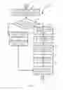
FIG. 1 is a block diagram of one embodiment of an electronic device and a toy.
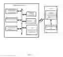
FIG. 2 is a block diagram of one embodiment of modules of a controlling system.
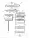
FIG. 3 illustrates a flowchart of one embodiment of a method for controlling the toy using the electronic device of FIG. 1.
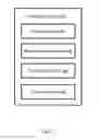
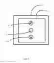
FIG. 4 illustrates an example of a control interface.
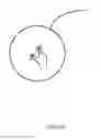
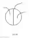
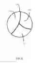
FIGS. 5A-5C illustrate an example of dividing a function button into different areas.
DETAILED DESCRIPTION
It will be appreciated that for simplicity and clarity of illustration, where appropriate, reference numerals have been repeated among the different figures to indicate corresponding or analogous elements. In addition, numerous specific details are set forth in order to provide a thorough understanding of the embodiments described herein. However, it will be understood by those of ordinary skill in the art that the embodiments described herein can be practiced without these specific details. In other instances, methods, procedures, and components have not been described in detail so as not to obscure the related relevant feature being described. Also, the description is not to be considered as limiting the scope of the embodiments described herein. The drawings are not necessarily to scale and the proportions of certain parts may be exaggerated to better illustrate details and features of the present disclosure.
The present disclosure, including the accompanying drawings, is illustrated by way of examples and not by way of limitation. It should be noted that references to “an” or “one” embodiment in this disclosure are not necessarily to the same embodiment, and such references mean “at least one.”
Furthermore, the term “module”, as used herein, refers to logic embodied in hardware or firmware, or to a collection of software instructions, written in a programming language, such as, Java, C, or assembly. One or more software instructions in the modules can be embedded in firmware, such as in an EPROM. The modules described herein can be implemented as either software and/or hardware modules and can be stored in any type of non-transitory computer-readable medium or other storage device. Some non-limiting examples of non-transitory computer-readable media include CDs, DVDs, BLU-RAY, flash memory, and hard disk drives.
FIG. 1 is a block diagram of one embodiment of an electronic device and a toy. Depending on the embodiment, an electronic device 1 includes a controlling system 10, a three-dimensional (3D) touch screen 11, a gyroscope sensor 12, a storage device 13, at least one processor 14, and a first communication device 15. The above components can connect to each other via a data bus. The electronic device 1 can be a smart phone, a personal digital assistant (PDA), a tablet computer, or any other suitable electronic device. A toy 2 can include a second communication device 21 and a driver module 22.
FIG. 1 illustrates only one example of the electronic device 1 and the toy 2 that can include more or fewer components than illustrated, or have a different configuration of the various components in other embodiments. For example, the electronic device 1 and the toy 2 may further include a voice module.
In at least one embodiment, the electronic device 1 can communicate with the toy 2 using the first communication device 15 and the second communication device 21. The first communication device 15 and the second communication device 21 can provide a function of network communication and data transmission for the electronic device 1 and the toy 2, based on a wired or wireless network transmission method. The wired or wireless network transmission method may include, but are not limited to, a traditional network connection, general packet radio service (GPRS), wireless fidelity (WIFI).
In at least one embodiment, the controlling system 10 can control a movement speed of the toy 2 via the driver module 22, according to a pressure value detected by the 3D touch screen 11. Details will be provided in the following paragraphs.
The gyroscope sensor 12 can detect a rotation direction of the electronic device 1.
The storage device 13 can be an internal storage device, such as a flash memory, a random access memory (RAM) for temporary storage of information, and/or a read-only memory (ROM) for permanent storage of information. The storage device 13 can also be an external storage device, such as an external hard disk, a storage card, or a data storage medium.
The at least one processor 14 can be a central processing unit (CPU), a microprocessor, or other data processor chip that performs functions of the electronic device 1.
FIG. 2 is a block diagram of one embodiment of modules of the controlling system 10. In at least one embodiment, the controlling system 10 can include a display module 101, a determination module 102, a detection module 103, and a control module 104. The modules 101-104 can include computerized codes in the form of one or more programs, which are stored in the storage device 13, and are executed by the at least one processor 14 of the electronic device 1 to control the toy 2.
FIG. 3 illustrates a flowchart which is presented in accordance with an example embodiment. The example method 100 is provided by way of example, as there are a variety of ways to carry out the method. The method 100 described below can be carried out using the configurations illustrated in FIG. 1, for example, and various elements of these figures are referenced in explaining example method 100. Each block shown in FIG. 3 represents one or more processes, methods, or subroutines, carried out in the exemplary method 100. Additionally, the illustrated order of blocks is by example only and the order of the blocks can be changed according to the present disclosure. The exemplary method 100 can begin at block 301. Depending on the embodiment, additional steps can be added, others removed, and the ordering of the steps can be changed.
At block 301, the display module 101 can generate a control interface and display the control interface on the 3D touch screen 11. In at least one embodiment, the control interface includes at least on function button. The at least one function button may include, but are not limited to, a forward button that is used to control the toy 2 to move forward, a backward button that is used to control the toy 2 to move backward, and a stop button that is used to control the toy 2 to stop.
For example, as shown in FIG. 4, the display module 101 generates a control interface 110, and display the control interface 110 on the 3D touch screen 11. The control interface 110 includes three function buttons, the three function buttons include a forward button 41, a backward button 42, and a stop button 43.
At block 302, the determination module 102 can determine whether a user of the electronic device 1 needs to divide the at least one function button into different areas. When the user needs to divide the at least on function button into different areas, the process goes to block 3021. When the user does not need to divide the at least on function button into different areas, the process goes to block 3031.
In at least one embodiment, the determination module 102 can display a dialog box on the 3D touch screen 11, and ask the user whether the at least one function button should be divided into different areas using the dialog box. The determination module 102 further determines whether the user needs to divide the at least on function button into different areas or not, according to a selection from the dialog box of the user.
At block 3021, the detection module 103 can divide the at least one function button into a specified number of areas in response to a user operation.
In at least one embodiment, the detection module 103 can averagely divide the at least one function button into the specified number of areas. In other words, each of the specified number of areas has a same size.
In other embodiments, the detection module 103 can divide the at least one function button into the specified number of areas according to a preset proportion. In other words, a size of each of the specified number of areas is determined according to the preset proportion.
In at least one embodiment, the detection module 103 can predetermine a variety of user operations correspond to a plurality of specified number of areas. In other words, the number of areas is determined according to the user operation.
For a first example, as shown in FIG. 5A, if the detection module 103 detects that a distance between two fingers of the user on the forward button 41 is increased, the detection button 103 can averagely divide the forward button 41 into two areas. The two areas include a first area 411 and a second area 412 as shown in FIG. 5B. For a second example, if the detection module 103 detects that a distance between each other of three fingers of the user on the forward button 41 is increased, the detection module 103 can averagely divide the forward button 41 into three areas. The three areas include a third area 511, a fourth area 512, and a fifth area 513 as shown in FIG. 5C. Similarly, the detection module 103 can averagely divide the forward button 41 into four areas, five areas and so on.
In other embodiments, the detection module 103 can generate a line, and display the generated line on the at least one function button to divide the at least one function button.
In other embodiments, the detection module 103 can divide the at least one function button into a plurality of areas according to one or more lines that are generated according to sliding operations of the user on the at least one function button. The one or more lines can include, but are limited to, straight lines, bending lines.
At block 3022, the determination module 102 can determine each of the specified number of areas corresponds to an acceleration speed.
For example, it is assumed that the detection module 103 divides the forward button 41 into the first area 411 and the second area 412. The determination module 102 can determine the first area 411 corresponds to a first acceleration speed (e.g., 5 m/s2) in response to user's input. The determination module 102 can further determine the second area 412 corresponds to a second acceleration speed (e.g., 10 m/s2) in response to user's input.
At block 3023, the determination module 102 can determine one of the specified number of areas is pressed by the user, according to a pressure position on the at least on function button.
At block 3024, the determination module 102 can determine an acceleration speed for the toy 2 according to the pressed area.
For example, it is assumed that the first area 411 is pressed by the user, then the determination module 102 determines the acceleration speed of the toy 2 is 5 m/s2.
At block 3025, the control module 104 can control the toy 2 to execute a function corresponding to the at least one function button, based on the determined acceleration speed.
For a first example, if the user presses the forward button 41, the control module 104 can control the toy 2 to move forward based on the determined acceleration speed.
For a second example, if the user presses the backward button 42, the control module 104 can control the toy 2 to move backward based on the determined acceleration speed.
For a third example, if the user presses the stop button 43, the control module 104 can control the toy 2 to stop based on the determined acceleration speed.
At block 3031, when the user does not need to divide the at least one function button, the detection module 103 can detect a pressure value of the user presses the at least one function button.
At block 3032, the determination module 102 can determine an acceleration speed for the toy 2 according to the detected pressure value. When the block 3032 is executed, the process goes to block 3025.
In at least one embodiment, the detection module 103 can predetermine different pressure value ranges corresponding to different acceleration speeds. Therefore, when the pressure value is detected, the acceleration speed of the toy 2 can be determined.
In at least one embodiment, the determination module 102 can detect a rotation direction of the electronic device 1 using the gyroscope sensor 12. The control module 104 can control the toy 2 to rotate according to the rotation direction of the electronic device 1. For example, if the electronic device 1 rotates right, the control module 104 can control the toy 2 to rotate right.
It should be emphasized that the above-described embodiments of the present disclosure, including any particular embodiments, are merely possible examples of implementations, set forth for a clear understanding of the principles of the disclosure.
Many variations and modifications can be made to the above-described embodiment(s) of the disclosure without departing substantially from the spirit and principles of the disclosure. All such modifications and variations are intended to be included herein within the scope of this disclosure and protected by the following claims.
Claims
What is claimed is:1. A method for controlling a toy using an electronic device, the electronic device comprising a three-dimensional (3D) touch screen, the method comprising:
generating a control interface comprising at least one function button;
displaying the control interface on the 3D touch screen;
detecting, when the at least one function button is not divided into different areas, a pressure value at the at least one function button;
determining an acceleration speed for the toy according to the detected pressure value; and
controlling the toy to execute a function corresponding to the at least one function button based on the determined acceleration speed.
2. The method according to claim 1, further comprising:
predetermining different pressure value ranges corresponding to different acceleration speeds.
3. The method according to claim 1, further comprising:
dividing the at least one function button into a specified number of areas in response to a user operation;
determining each of the specified number of areas corresponds to an acceleration speed;
determining one of the specified number of areas is pressed by the user, according to a pressure position on the at least on function button; and
determining an acceleration speed for the toy according to the pressed area.
4. The method according to claim 3, wherein the at least one function button is averagely divided into the specified number of areas; or the at least one function button is divided into the specified number of areas according to a preset proportion.
5. The method according to claim 1, further comprising:
detecting a rotation direction of the electronic device using a gyroscope sensor of the electronic device; and
controlling the toy to rotate according to the rotation direction of the electronic device.
6. An electronic device comprising:
a three-dimensional (3D) touch screen;
at least one processor; and
a storage device configured to store one or more programs that, when executed by the at least one processor, cause the at least one processor to:
generate a control interface comprising at least one function button;
display the control interface on the 3D touch screen;
detect, when the at least one function button is not divided into different areas, a pressure value at the at least one function button;
determine an acceleration speed for the toy according to the detected pressure value; and
control the toy to execute a function corresponding to the at least one function button based on the determined acceleration speed.
7. The electronic device according to claim 6, wherein the at least one processor is further caused to:
predetermine different pressure value ranges corresponding to different acceleration speeds.
8. The electronic device according to claim 6, wherein the at least one processor is further caused to:
divide the at least one function button into a specified number of areas in response to a user operation;
determine each of the specified number of areas corresponds to an acceleration speed;
determine one of the specified number of areas is pressed by the user, according to a pressure position on the at least on function button; and
determine an acceleration speed for the toy according to the pressed area.
9. The electronic device according to claim 8, wherein the at least one function button is averagely divided into the specified number of areas; or the at least one function button is divided into the specified number of areas according to a preset proportion.
10. The electronic device according to claim 6, wherein the at least one processor is further caused to:
detect a rotation direction of the electronic device using a gyroscope sensor of the electronic device; and
control the toy to rotate according to the rotation direction of the electronic device.
11. A non-transitory storage medium having stored thereon instructions that, when executed by a processor of an electronic device, causes the processor to perform a method for controlling a toy, the electronic device comprising a storage device and a three-dimensional (3D) touch screen, wherein the method comprises:
generating a control interface comprising at least one function button;
displaying the control interface on the 3D touch screen;
detecting, when the at least one function button is not divided into different areas, a pressure value at the at least one function button;
determining an acceleration speed for the toy according to the detected pressure value; and
controlling the toy to execute a function corresponding to the at least one function button based on the determined acceleration speed.
12. The non-transitory storage medium according to claim 11, further comprising:
predetermining different pressure value ranges corresponding to different acceleration speeds.
13. The non-transitory storage medium according to claim 11, further comprising:
dividing the at least one function button into a specified number of areas in response to a user operation;
determining each of the specified number of areas corresponds to an acceleration speed;
determining one of the specified number of areas is pressed by the user, according to a pressure position on the at least on function button; and
determining an acceleration speed for the toy according to the pressed area.
14. The non-transitory storage medium according to claim 13, wherein the at least one function button is averagely divided into the specified number of areas; or the at least one function button is divided into the specified number of areas according to a preset proportion.
15. The non-transitory storage medium according to claim 11, further comprising:
detecting a rotation direction of the electronic device using a gyroscope sensor of the electronic device; and
controlling the toy to rotate according to the rotation direction of the electronic device.
Images & Drawings included:
Sources:
- United States Patent and Trademark Office - verify current appl. status at the USPTO↗
Recent applications in this class:
- » 20250114719 2025-04-10
SYSTEM AND METHOD FOR TIPPING DURING A LIVESTREAM - » 20240269576 2024-08-15
MEDIA SYNCHRONIZED CONTROL OF PERIPHERALS - » 20240226764 2024-07-11
SYSTEM AND METHOD TO IMPROVE RADIO CONTROL VEHICLE TIRE PERFORMANCE - » 20240131444 2024-04-25
SYSTEM AND METHOD TO IMPROVE RADIO CONTROL VEHICLE TIRE PERFORMANCE - » 20240058717 2024-02-22
Remote control - » 20240058716 2024-02-22
Method and Device for Controlling Linear Brakes of Remote-controlled Model Racing Cars - » 20230201735 2023-06-29
Remote control - » 20230173400 2023-06-08
DEVICES, SYSTEMS, AND METHODS FOR ENHANCING THE GAMEPLAY OF TOY - » 20230080186 2023-03-16
REMOTE CONTROL MODEL CAR AND CONSOLE - » 20220395761 2022-12-15
DRAG RACING STABILITY MANAGEMENT FOR A MODEL VEHICLE
Recent applications for this Assignee:
- » 20250218287 2025-07-03
METHOD OF GENERATING AND PROMPTING TRAFFIC INFORMATION, AND ROADSIDE DEVICE THEREOF - » 20250178535 2025-06-05
METHOD FOR CONSTRUCTING 3D PANORAMIC VIEW MODEL, VEHICLE-MOUNTED DEVICE, AND STORAGE MEDIUM - » 20250074444 2025-03-06
METHOD FOR EARLY WARNING A BLIND AREA, ELECTRONIC DEVICE AND STORAGE MEDIUM - » 20240416754 2024-12-19
DISPLAY CONTROL DEVICE, DISPLAY EQUIPMENT, AND VEHICLE EMPLOYING DEVICE - » 20240411051 2024-12-12
Light-emitting device array and optical transceiver system having the same - » 20240324114 2024-09-26
DISPLAY CONTROL DEVICE AND VEHICLE EMPLOYING DEVICE - » 20240295957 2024-09-05
METHOD FOR CONTROLLING ELECTRONIC DEVICE, ELECTRONIC DEVICE AND COMPUTER STROAGE MEDIUM EMPLOYING METHOD - » 20240257357 2024-08-01
METHOD FOR DETECTING OBSTACLES, ELECTRONIC DEVICE, AND STORAGE MEDIUM - » 20240203133 2024-06-20
LANE LINE RECOGNITION METHOD, ELECTRONIC DEVICE AND STORAGE MEDIUM - » 20240194999 2024-06-13
Robot using limiting device for locking battery