Structure formed from composite material
US20170173919A1
2017-06-22
15/382,186
2016-12-16
✅ Patent granted
US 11,801,666 B2
2023-10-31
-
-
Monique R Jackson
KDW Firm PLLC
2037-12-03
Abstract:
A structure formed from composite material and method of forming a composite structure is disclosed in which one or more metal layers are disposed on a composite structural member.
Assignee:
- AIRBUS OPERATIONS LIMITED 1,080 🇬🇧 Bristol, United Kingdom
Applicant:
Interested in similar patents?
Get notified when new applications in this technology area are published.
Classification:
B32B37/14 » CPC further
Methods or apparatus for laminating, e.g. by curing or by ultrasonic bonding characterised by the properties of the layers
B32B15/04 » CPC main
Layered products comprising a layer of metal comprising metal as the main or only constituent of a layer, next to another layer of a
B32B2255/00 » CPC further
Coating on the layer surface
B32B3/266 » CPC further
Layered products comprising a layer with external or internal discontinuities or unevennesses, or a layer of non-planar form ; Layered products having particular features of form characterised by a particular shape of the outline of the cross-section of a continuous layer; characterised by a layer with cavities or internal voids ; characterised by an apertured layer characterised by an apertured layer, the apertures going through the whole thickness of the layer, e.g. expanded metal, perforated layer, slit layer regular cells
B32B15/043 » CPC further
Layered products comprising a layer of metal comprising metal as the main or only constituent of a layer, next to another layer of a of metal
B32B2255/06 » CPC further
Coating on the layer surface on metal layer
B32B2255/205 » CPC further
Coating on the layer surface; Inorganic coating Metallic coating
B32B2260/046 » CPC further
Layered product comprising an impregnated, embedded, or bonded layer wherein the layer comprises an impregnation, embedding, or binder material; Impregnation, embedding, or binder material Synthetic resin
B32B2262/106 » CPC further
Composition or structural features of fibres which form a fibrous or filamentary layer or are present as additives; Inorganic fibres Carbon fibres, e.g. graphite fibres
B32B2307/202 » CPC further
Properties of the layers or laminate having particular electrical or magnetic properties, e.g. piezoelectric Conductive
B32B2307/732 » CPC further
Properties of the layers or laminate; Other properties Dimensional properties
B32B2605/00 » CPC further
Vehicles
B32B2605/18 » CPC further
Vehicles Aircraft
B32B15/14 » CPC main
Layered products comprising a layer of metal next to a fibrous or filamentary layer
B32B5/26 » CPC further
Layered products characterised by the non- homogeneity or physical structure, i.e. comprising a fibrous, filamentary, particulate or foam layer; Layered products characterised by having a layer differing constitutionally or physically in different parts characterised by the presence of two or more layers which are next to each other and are fibrous, filamentary, formed of particles or foamed one layer being a fibrous or filamentary layer another layer also being fibrous or filamentary
B32B3/26 IPC
Layered products comprising a layer with external or internal discontinuities or unevennesses, or a layer of non-planar form ; Layered products having particular features of form characterised by a particular shape of the outline of the cross-section of a continuous layer; characterised by a layer with cavities or internal voids ; characterised by an apertured layer
B32B15/02 » CPC further
Layered products comprising a layer of metal Layer formed of wires, e.g. mesh
B64D45/02 » CPC further
Aircraft indicators or protectors not otherwise provided for Lightning protectors; Static dischargers
B32B5/02 » CPC further
Layered products characterised by the non- homogeneity or physical structure, i.e. comprising a fibrous, filamentary, particulate or foam layer; Layered products characterised by having a layer differing constitutionally or physically in different parts characterised by structural features of a layer
B32B7/12 » CPC further
Layered products characterised by the relation between layers; Layered products characterised by the relative orientation of features between layers, or by the relative values of a measurable parameter between layers, i.e. products comprising layers having different physical, chemical or physicochemical properties; Layered products characterised by the interconnection of layers; Interconnection of layers using interposed adhesives or interposed materials with bonding properties
B33Y10/00 » CPC further
Processes of additive manufacturing
B32B15/20 » CPC further
Layered products comprising a layer of metal comprising aluminium or copper
B32B2260/023 » CPC further
Layered product comprising an impregnated, embedded, or bonded layer wherein the layer comprises an impregnation, embedding, or binder material; Composition of the impregnated, bonded or embedded layer; Fibrous or filamentary layer Two or more layers
Description
FIELD OF TECHNOLOGY
The present technology relates to structures formed from composite material. The technology further relates to a composite material comprising an electrically conductive outer layer for dissipating electric charge and a method of manufacturing such a composite material.
BACKGROUND
Synthetic composite materials such as carbon fibre reinforced plastic (CFRP) commonly comprise a set of one or more layers or plies of carbon fibre cloth or matrix laminated together with a resin to form a desired structure. The carbon fibre plies may be impregnated with resin prior to being laid-up to form the required structure or the resin may be applied to plain carbon fibre plies during the lay-up process. Resins are commonly thermosetting with the laid-up structure being heated, for example, in an autoclave, to cure the structure. The cured structure may then be keyed for painting, for example, by grit blasting the surface to be painted, prior to paint being applied.
BRIEF SUMMARY OF THE TECHNOLOGY
Embodiment of the present technology provide a structure comprising: a composite structural member comprising: a first set of layers comprising a synthetic composite material; and a plurality of adjoined metallic second layers disposed on the first layer, and a metallic third layer disposed on the composite structural member at least partially overlaying at least part of the joint between two of the metallic second layers.
The first and second layers may be integrally formed. At least one of the second layers may be substantially covered by a matrix material. One or more of the second layers may comprise a foramenous metal layer. One or more of the second layers may comprise metallic mesh, gauze or expanded foil. One or more of the second layers may comprise copper or bronze. The second layers may be joined by a lap joint. The second layers may be joined by a butt joint.
The third layer may comprise a metal film. The third layer may comprise a thermally applied metal film. The third layer may comprise aluminium or copper or silver or zinc or nickel. The metal of the third layer may be selected so as to be galvanically compatible with the metal of the second layer. The third layer may comprise a metal film less than 15 μm thick. The third layer may comprise a metal film less than 25 μm thick. The third layer may comprise a metal film less than 50 μm thick.
Another embodiment of the present technology provides a method for forming a structure comprising the steps of: forming a composite structural member comprising: a first layer comprising a synthetic composite material; and a plurality of adjoined metallic second layers disposed on the first layer, and disposing a metallic third layer on a first surface of the composite structural member at least partially overlaying at least part of the joint between two second layers.
The method may comprise the further step of: applying a keying treatment to the first surface of the composite structural member prior to disposing the third layer. The method may comprise the further step of: applying a paint coat to the first surface of the composite structural member and the third layer.
A further embodiment of the present technology provides a structure substantially as disclosed herein with respect to FIG. 2. Another embodiment of the present technology provides a structure substantially as disclosed herein with respect to FIG. 3. A further embodiment of the present technology provides a method of manufacturing a structure substantially as disclosed herein with respect to FIGS. 4a & 4c.
BRIEF DESCRIPTION OF THE DRAWINGS
Embodiments of the technology will now be described, by way of example only, with reference to the following drawings in which:
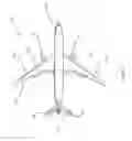
FIG. 1 is a perspective side view of an aircraft partially formed from synthetic composite material in the form of CFRP;
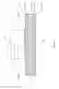
FIG. 2 is a cross sectional view of a CFRP structural element of the aircraft of FIG. 1, in accordance with an embodiment of the present technology;
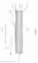
FIG. 3 is a cross sectional view of a CFRP structural element of the aircraft of FIG. 1, in accordance with another embodiment of the present technology; and
FIGS. 4a, 4b, 4c & 4d are successive cross sectional views illustrating manufacturing steps for the structural element of FIG. 2.
DETAILED DESCRIPTION OF EMBODIMENTS OF THE TECHNOLOGY
With reference to FIG. 1, an aircraft 101 comprises a pair of wings 103 faired into a fuselage 105. The wings 103 each carry an engine 107. The aircraft further comprises horizontal stabilizers 109 and a vertical tail plane 111 each attached at the rear of the fuselage 105. The aircraft 101 comprises structural elements that are formed from carbon fibre reinforced plastic material (CFRP). For example, the wings 103 comprise exterior structural members in the form of wing covers 113 formed from CFRP.
With reference to the cross sectional view of FIG. 2, each of the wing covers 113 comprises a composite structural member 201 made up of layers of carbon fibre layers 203 bound in matrix layers 205 of a thermoset polymer. The upper surface of the wing cover 113 in FIG. 2, which, in use, comprises the exterior surface of the wing 103, comprises a plurality of metallic layers 207a, 207b. Each of the metallic layers 207a, 207b comprises a metal layer 209 substantially covered or encapsulated in the matrix 211. In the present embodiment, the metallic layers 207a, 207b are adjoined by a lap joint 213 having a predetermined width. The metallic layers 207a. 207b are co-formed as part of the composite structural member 201. In other words, the composite structural member 201 comprises an upper or outer electrically conductive layer provided by the metallic layers 207a, 207b.
The metallic layers 207a, 207b are arranged to provide a conductive layer in the surface of the structural member 201 for dissipating electrical charge resulting from static electricity or lightening strike. The metal layer 209 of the metallic layers 207a, 207b in the present embodiment is provided by expanded copper foil (ECF) or bronze gauze (BG). The structure of ECF or BG provides a continuous metallic layer that also defines holes, in other words, the metal layer 209 is foramenous. The foramenous nature of the metal layer 209 means the metallic layers 207a, 207b are more flexible, thus aiding their laying up into the composite structure 201 and also improves the combined structural integrity of the matrix 211 and metal layer 209.
The wing skin 113 comprises a further metallic layer 217 disposed on the exterior surface of the wing skin 113 and extending over the lap joint 213. In the present embodiment, the metallic layer 217 at least partially overlaps at least part of the lap joint 213 and is formed of a metallic film. In the present embodiment, the metallic layer 217 comprises a 15 μm thick layer of aluminium and is applied by a thermal spray deposition method. Aluminium is highly electrically conductive and also galvanically compatible with the ECF or MB of the other metallic layers 207a, 207b.
The overlap in the joint 213 provides electrical connectivity between the second metallic layers 207a. 207b. In some areas of the joint 213 the respective metal layers 209 may be in direct physical and electrical contact and in other areas the metal layers 209 may be at least partially separated by matrix material 211. In response to electrical charge in one of the metal layers 209 at the joint 213 exceeding a threshold, interposed matrix material 211 electrically breaks down and thus provides a path for conduction of the charge between the metal layers 209. As will be understood by those skilled in the art, such electrical breakdown of the interposed matrix material 211 is likely to be significantly energetic. The metallic layer 217 is arranged to contain such energetic events away from the external surface of the wing skin 113 by providing further paths for dissipation of the electrical charge into the regions of the metallic layers 207a, 207b surrounding the joint 213.
Further embodiments of the technology are described below with reference to respective figures in which, for clarity, the same nomenclature is used between figures for elements are common between embodiments.
In another embodiment of the technology, with reference to FIG. 3, the second metallic layers 207a, 207b are joined by a butt joint 301 substantially free of overlap.
A method for manufacturing the composite structure of FIG. 2 will now be described with reference to FIG. 4a to 4d. In FIG. 4a, the wing skin 113 is formed using known composite material forming techniques to lay up layers of carbon fibre 203 pre-impregnated with matrix material 205 in the form of thermosetting polymer resin. The wing skin 113 is then heated in an autoclave to cure CFRP material. With reference to FIG. 4b, a keying process is applied to the exterior surface 401 of the wing skin 113 to provide a surface key 403 to aid adhesion of subsequent layers. In the present embodiment, the keying process is grit blasting. With reference to FIG. 4c, the metallic layer 217 is applied to the upper surface 401 over the joint 213. In the present embodiment, the metallic layer 217 comprises aluminium up to 15 μm thick and applied by a thermal spay deposition method. With reference to FIG. 4d, a paint system 405 is applied to the exterior surface 401 of the wing skin 113 and the exposed surface of the metallic layer 217.
In another embodiment of the technology, the metallic layer 217 is up to 25 μm thick. In a further embodiment of the technology, the metallic layer 217 is up to 50 μm thick. As will be understood by those skilled in the art, the metallic layer 217 may be formed from any other suitable metal such as copper or silver or zinc or nickel or any relevant alloy thereof. The metallic layer 217 may be disposed on the structural member by any suitable means or method not limited to thermal spraying methods, for example, cold metal spray, plasma or vapour deposition or printing. The gauze or expanded foil of the metallic layers 207 may be substituted for any other suitable structure or combination of structures such as gauze.
In another embodiment, the joint between the metallic layers 207 is part lap joint and part butt joint.
As will be understood by those skilled in the art, the keying technique is not limited to grit blasting as described above but keying may be achieved by any other suitable method of roughening or ablating a surface. Examples of possible suitable techniques include the application of a mechanical tool or material, chemical etching, the inclusion of a sacrificial peel ply in the surface of the composite material or laser ablation.
As will be understood by those skilled in the art, the technology described herein is not limited in application to any particular aircraft structure and may be applied to any structure of an aircraft. As will be understood by those skilled in the art, the technology described herein may be applied to any type of structure, including automotive, space, maritime or civil engineering structures where a conductive exterior layer is affixed to a composite structural element. The technology may be applied to a selected part or substantially the whole of any such structure.
As will be understood by those skilled in the art, the whole or a selected part or layer of the structure in accordance with the technology described herein may be provided using additive layer manufacturing (ALM) techniques or three-dimension printing (3DP) techniques. For example, either of the metallic layers may be applied to a composite part by ALM or 3DP.
While the present technology has been illustrated by the description of the embodiments thereof, and while the embodiments have been described in considerable detail, it is not the intention of the applicant to restrict or in any way limit the scope of the appended claims to such detail. Additional advantages and modifications will readily appear to those skilled in the art. Therefore, the technology in its broader aspects is not limited to the specific details of the representative apparatus and method, and illustrative examples shown and described. Accordingly, departures may be made from such details without departure from the scope of applicant's general inventive concept.
Claims
1. A structure comprising:
a composite structural member comprising:
a first set of layers comprising a synthetic composite material; and
a plurality of adjoined metallic second layers disposed on the first layer, and
a metallic third layer disposed on the composite structural member at least partially overlaying at least part of the joint between two of the metallic second layers.
2. A structure according to claim 1 in which the first and second layers are integrally formed.
3. A structure according to claim 1 in which at least one of the second layers is substantially covered by a matrix material.
4. A structure according to claim 1 in which one or more of the second layers comprises a foramenous metal layer.
5. A structure according to claim 1 in which one or more of the second layers comprises metallic mesh, gauze or expanded foil.
6. A structure according to claim 1 in which one or more of the second layers comprises copper or bronze.
7. A structure according to claim 1 in which the second layers are joined by a lap joint.
8. A structure according to claim 1 in which the second layers are joined by a butt joint.
9. A structure according to claim 1 in which the third layer comprises a metal film.
10. A structure according to claim 1 in which the third layer comprises a thermally applied metal film.
11. A structure according to claim 1 in which the third layer comprises aluminium or copper or silver or zinc or nickel.
12. A structure according to claim 1 in which the metal of the third layer is selected so as to be galvanically compatible with the metal of the second layer.
13. A structure according to claim 1 in which the third layer comprises a metal film less than 15 μm thick.
14. A structure according to claim 1 in which the third layer comprises a metal film less than 25 μm thick.
15. A structure according to claim 1 in which the third layer comprises a metal film less than 50 μm thick.
16. A method for forming a structure comprising the steps of:
forming a composite structural member comprising:
a first layer comprising a synthetic composite material; and
a plurality of adjoined metallic second layers disposed on the first layer, and
disposing a metallic third layer on a first surface of the composite structural member at least partially overlaying at least part of the joint between two second layers.
17. A method according to claim 16 comprising the further step of:
applying a keying treatment to the first surface of the composite structural member prior to disposing the third layer.
18. A method according to claim 16 comprising the further step of:
applying a paint coat to the first surface of the composite structural member and the third layer.
19. (canceled)
20. (canceled)
21. (canceled)
Images & Drawings included:


Sources:
- United States Patent and Trademark Office - verify current appl. status at the USPTO↗
Similar patent applications:
- » 20130034674
Composite structural material formed product and packaging material using the same, method for producing the composite structural material, and coating liquid - » 20220371260
ANNULAR STRUCTURES FORMED FROM COMPOSITE MATERIALS AND SYSTEMS AND METHODS FOR FORMING ANNULAR STRUCTURES FROM COMPOSITE MATERIALS - » 20130199709
Composite material structure forming method - » 20150209983
Methods of forming composite structures and methods of forming material with a removable backing for composite structures - » 20170174312
Structure formed from composite material - » 20140177936
System and method for inspecting structures formed of composite materials during the fabrication thereof - » 20150343720
Manufacture of integrated structures formed of composite materials - » 20060210929
Photosensitive composition and forming process of structured material using the composition - » 20130263542
Structural assembly formed of composite materials - » 20140248449
Composite structure, packaging material and formed product using same, production methods thereof, and coating liquid
Recent applications in this class:
- » 20250205996 2025-06-26
RESIN-METAL COMPOSITE PANEL - » 20250010580 2025-01-09
LOW-EMISSIVITY AND ANTI-SOLAR GLAZING - » 20250001732 2025-01-02
COMPOSITE SUBSTRATE, LAMINATE, METHOD FOR PRODUCING COMPOSITE SUBSTRATE, AND METHOD FOR PRODUCING LAMINATE - » 20240399711 2024-12-05
MAGNESIUM ALLOY CONNECTION MECHANICAL PART, ELECTRONIC DEVICE, AND COMPONENT FORMING METHOD - » 20240308181 2024-09-19
FLEXIBLE DISPLAY DEVICE AND UPPER FILM THEREFOR - » 20220203653 2022-06-30
TRANSPARENT TINTED COATING FOR APPLIANCE EXTERIOR PANELS TO ALLOW FOR TINTED SURFACE PATTERNS AND A PROCESS FOR APPLICATION OF COATING - » 20220055343 2022-02-24
Structure body, structure body manufacturing method, and electronic apparatus - » 20210187907 2021-06-24
OPTICAL FILTER AND OPTICAL DEVICE UTILIZING SAME - » 20210101365 2021-04-08
Method for forming non-bonded regions in multi-layered metallic armor - » 20200398531 2020-12-24
Radiative cooling device
Recent applications for this Assignee:
- » 20250065357 2025-02-27
APPLICATOR - » 20250039266 2025-01-30
AVIONICS UNIT - » 20240336351 2024-10-10
Wing tip device - » 20240327037 2024-10-03
PINTLE SUPPORT AND METHOD OF INSTALLING A LANDING GEAR ASSEMBLY - » 20240286762 2024-08-29
METHOD OF FABRICATING AN AIRCRAFT STRUCTURAL COMPONENT - » 20240253772 2024-08-01
SPOILER - » 20240253766 2024-08-01
AIRCRAFT ASSEMBLY WITH MOVEABLE DEVICE - » 20240239516 2024-07-18
AIRCRAFT SUB-ASSEMBLY MANUFACTURING SYSTEM AND METHOD - » 20240227751 2024-07-11
CONTROL DEVICE AND METHOD FOR AN AIRCRAFT - » 20240208641 2024-06-27
AIRCRAFT STRUCTURE COMPONENT FOR LAMINAR FLOW